MAZDA PROTEGE 1992 Workshop Manual
Manufacturer: MAZDA, Model Year: 1992, Model line: PROTEGE, Model: MAZDA PROTEGE 1992Pages: 1164, PDF Size: 81.9 MB
Page 1051 of 1164

PARTS
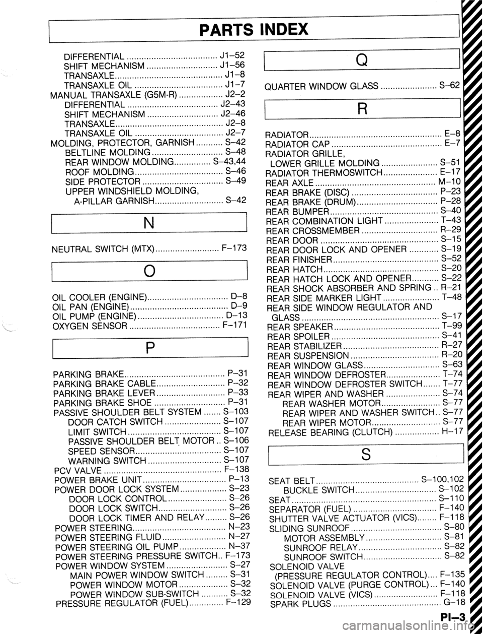
DIFFERENTIAL ..................................... Jl-52
SHIFT MECHANISM ............................. Jl-56
TRANSAXLE ............................................ Jl-8
TRANSAXLE OIL .................................... Jl-7
MANUAL TRANSAXLE (G5M-R) .................. J2-2
DIFFERENTIAL ..................................... J2-43
SHIFT MECHANISM ............................. J2-46
TRANSAXLE.. .......................................... J2-8
TRANSAXLE OIL .................................... J2-7
MOLDING, PROTECTOR, GARNISH ...........
S-42
BELTLINE MOLDING ............................. S-48
REAR WINDOW MOLDING.. ............. S-43,44
ROOF MOLDING.. .................................. S-46
SIDE PROTECTOR ................................. S-49
UPPER WINDSHIELD MOLDING,
A-PILLAR GARNISH ............................ S-42
NEUTRAL SWITCH (MTX) . . . . . . . . . . . . . . . . . . . . . . . . . . F-l 73
0
1
\_ OIL COOLER (ENGINE). ................................ D-8
OIL PAN (ENGINE) ........................................ D-9
OIL PUMP (ENGINE) ................................... D-l 3
..................................... F-l 71
OXYGEN SENSOR
P
PARKING BRAKE ......................................... P-31
PARKING BRAKE CABLE ............................ P-32
PARKING BRAKE LEVER ............................ P-33
PARKING BRAKE SHOE ............................. P-31
PASSIVE SHOULDER BELT SYSTEM.. ..... S-103
DOOR CATCH SWITCH ....................... S-l 07
LIMIT SWITCH ...................................... S-l 07
PASSIVE SHOULDER BELT MOTOR.. S-106
SPEED SENSOR ................................... S-l 07
WARNING SWITCH .............................. S-l 07
PCV VALVE ................................................
POWER BRAKE UNIT ‘;--=I;;
..................................
POWER DOOR LOCK SYSTEM ................... S-23
DOOR LOCK CONTROL.. ...................... S-26
DOOR LOCK SWITCH.. .......................... S-26
DOOR LOCK TIMER AND RELAY.. ....... S-26
POWER STEERING.. .................................... N-23
POWER STEERING FLUID .......................... N-27
POWER STEERING OIL PUMP.. ................. N-37
POWER STEERING PRESSURE SWITCH . . F-l 73
POWER WINDOW SYSTEM.. .......................
S-27
MAIN POWER WINDOW SWITCH.. .......
S-31
POWER WINDOW MOTOR.. ..................
S-32
POWER WINDOW SUB-SWITCH ........... S-32
PRESSURE REGULATOR (FUEL). ............. F-l 29 . . . . . . . . , . . . . . , . RADIATOR CAP .............................................
E-7
RADIATOR GRILLE,
I
LOWER GRILLE MOLDING ....................... S-51 fl
RADIATOR THERMOSWITCH ...................... E-17 t
REAR AXLE ................................................. M-10
REAR BRAKE (DISC) ................................... P-23
REAR BRAKE (DRUM) ................................. P-28
REAR BUMPER ............................................ s-40
REAR COMBINATION LIGHT.. ....
REAR CROSSMEMBER ............................... R-29
REAR DOOR ................................................ S-l 5
REAR DOOR LOCK AND OPENER.. .
REAR FINISHER ........................................... s-52
REAR HATCH ............................................... s-20
REAR HATCH LOCK AND OPENER.. ......... S-22
REAR SHOCK ABSORBER AND SPRING.. R-21
REAR SIDE MARKER LIGHT ....................... T-48
REAR SIDE WINDOW REGULATOR AND . . . . . . . . .
AI .,.n
INDEX
Q
QUARTER WINDOW GLASS . . . . . . . . . . . . ..a........ S-62
R
RADIATOR . . . . . . . . . . . . . . . . . . . . . . . . . . . . . . . . . . . . . . . . . . . . . . . . . . . . . .
kiLA33 ........................................................ a-- I I
REAR SPEAKER ........................................... T-99
REAR SPOILER ............................................ s-41
REAR STABILIZER.. ..................................... R-27
REAR SUSPENSION .................................... R-20
REAR WINDOW GLASS ............................... S-63
REAR WINDOW DEFROSTER.. .................... T-74
REAR WINDOW DEFROSTER SWITCH ....... T-77
REAR WIPER AND WASHER ...................... S-74
REAR WASHER MOTOF
REAR WIPER AND WASHER SWITCH . . S-77
REAR WIPER MOTOR ............................ s-77
RELEASE BEARING (CLUTCH). . . . . . . . . . ..s..... H-17 I . . . . . . . . ...*. .*......*..
SEAT BELT.. ........................................ S-100,102
BUCKLE SWITCH.. ............................... S-l 02
SEAT ........................................................... s-110
SEPARATOR (FUEL) .................................. F-l 40
SHUTTER VALVE ACTUATOR (VICS) ........ F-l 18
SLIDING SUNROOF ..................................... S-80
MOTOR ASSEMBLY ............................... S-81
SUNROOF RELAY.. ................................ S-82
SUNROOF SWITCH.. .............................. S-82
SOLENOID VALVE
(PRESSURE REGULATOR CONTROL) .... F-135
SOLENOID VALVE (PURGE CONTROL). .. F-140
SOLENOID VALVE (VICS) .......................... F-l 18
SPARK PLUGS ............................................ G-18
-II__
Page 1052 of 1164

01 LAMP.., ., ,..... . . . . . . 9.. a.. . . . 9.e.. . . . . . . . . . . . . . . T-5233
ARTER .,,.,..,..,..,,....,..,......,........................ G-25
RTER INTERLOCK SWITCH .,............... G-31
ERING GEAR AND LINKAGE . . . . . . . . . . N-13,30
ERING KNUCKLE . . . . . . . . . . . . . . . . . . . . . . . . . . . . . . . . . . . M-5
TEERING WHEEL AND COLUMN . . . . . . . ,.. N-8,26
WITCH . . . . . . . . . . . . ..I..................... T-47
THERMOSTAT . . . . . ,.,..,......,.. . . . . . . . . . . . . . . . . . . . ..a..... . E-9
THROTTLE BODY . . . . . . . . . . . . . . . . . ..s............. . . . . . F-l 12
THROTTLE SENSOR .., . . . . . . . . . s............. . . . . . . . . F-l 69
TNS RELAY . . . . . . . . . . . . . . . . . . . . . . . . . . . . . . . . . . . . . . . . . . . . . . . . . . T-18
TRIM . . . . . . . . . . . . . . . . . . . . . . . . . . . . . . . . . . . . . . . . . . . . . . . . . . . . . . . . . . . . . S-97
TRUNK COMPARTMENT LAMP . . . . . . . . . . ..a..... T-54
TRUNK LID ,,.,...........,................................... S-33
TRUNK LID LOCK AND OPENER a.............. S-35
VACUUM CHAMBER (VICS) . . . . . . . . . . . . . . ..s..... F-l 19
AND INDICATOR LAMP . ..a........ T-60
BUZZER
AND TIMER . . . . . . . . . . . . . . . . . T-58
MP . . . . . . . . . . . . . . . . . . . . . . . . . . . . . . . . . . . . . . . . . . . . . . E-l 1
THERMOSENSOR s..........,.. F-l 68, T-72
THERMOSWITCH ..,,....................... E-l 6
ALIGNMENT . . . . . . . . . . . . . . . . . . . . . . . . . . . . . . . . . . . . . R-7
HEEL CYLINDER ,.............,..,.................... P-30
HEEL HUB .r,....,......................................... M-5
HEELS AND TIRES . . . . . . . . . . . . . . . . . . . . . . . . . . . . . . . . . . . . Q-3
INDSHIELD WIPER AND WASHER . . . . . . . . . . S-67
WASHER MOTOR ,.......,..,...................... S-71
WINDSHIELD WIPER
AND WASHER SWITCH s............,......... S-71
WIPER MOTOR ,....,,............................... S-70
INDSHIELD .,.......,.....,..,....,,....................... S-58
Page 1053 of 1164

Page 1054 of 1164

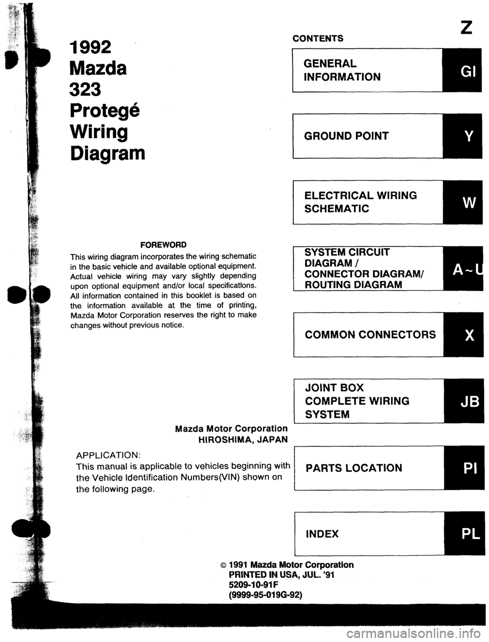
1992
Mazda
323
Protege
Wiring
Diagram
FOREWORD
This wiring diagram incorporates the wiring schematic
in the basic vehicle and available optional equipment.
Actual vehicle wiring may vary slightly depending
upon optional equipment and/or focal specifications.
All information contained in this booklet is based on
the information available at the time of printing,
Mazda Motor Corporation reserves the right to make
changes without previous notice.
Mazda Motor Corporation
HIROSHIMA, JAPAN
APPLICATION:
This manual is applicable to vehicles beginning with
the Vehicle Identification Numbers(VIN) shown on
the following page.
z CONTENTS
o 1991 Mazda Motor Corporation
PRINTED IN USA, JUL. ‘91
5209-l O-91 F
E (9999-95-0196-92)
Page 1055 of 1164

Z
SYSTEM INDEX
System Section System Section
AUDIO SYSTEM ......................................................... J
BACK-UP LIGHTS ...................................................
F-3
CHARGING SYSTEM ............................................... A-2
CIGARETTE LIGHTER ............................................... I-1
COMMON CONNECTOR LIST ..................................... X
COOLING FAN SYSTEM ....................................... B-3.4
COURTESY LAMPS .................................................. l-3
CRUISE CONTROL SYSTEM ...................................... Q
DAYTIME RUNNING UGHTS .................................... E-3
DIAGNOSIS CONNECTOR .......................................... U
DIGITAL CLOCK ....................................................... l-l
ELECTRICAL WIRING SCHEMATIC ............................. W
ENGINE CONTROL SYSTEM (MT) ................. B-l a, 1 b, 1 c
ENGINE 8 EC-AT CONTROL
SYSTEM (EC-AT) ...................................... B-2a,2b,2c
GENERAL INFORMATION .......................................... GI
GROUND POINT ........................................................ Y
HEADLIGHTS ....................................................... E-l ,2
HEATER 8 AIR CONDITIONER .................................... G
HORN .................................................................... F-3
IGNITION KEY CYLINDER LAMP ............................... l-2
ILLUMINATION LAMPS .............................................
l-4
INSTRUMENT CLUSTER . WARNING LAMPS .............. C INTER CONNECTING OF JOINT BOX ......................... JB
INTERIOR LAMP ...................................................... l-2
JOINT BOX .............................................................. JB
LICENSE PLATE UGHTS ......................................... E-4
PARTS INDEX ........................................................... PI
PARTS LOCATION ................................................... PL
PASSIVE SHOULDER BELT CONTROL SYSTEM .......... S
POSITION LIGHTS ................................................... E-4
POWER DOOR LOCK ............................................. K-2
POWER OUTSIDE MIRROR ......................................... L
POWER WINDOW ................................................... K-l
REAR SIDE MARKER LIGHTS.. ................................. E-4
REAR WINDOW DEFROSTER .................................... I-1
REAR WIPER 8 WASHER ........................................ D-3
SHIFT-LOCK SYSTEM ................................................ H
SLIDING SUNROOF ................................................... M
SOUND WARNING SYSTEM ...................................... l-2
STARTING SYSTEM ................................................ A-l
STOPLIGHTS .......................................................... F-2
TAILLIGHTS ............................................................ E-4
TRUNK COMPARTMENT LAMP ................................. l-3
TURN 8 HAZARD FLASHER UGHTS ......................... F-l
WINDSHIELD WIPER 8 WASHER .......................... D-l ,2
Page 1056 of 1164

VEHICLE IDENTIFICATION NUMBERS(VIN)
(CHASSIS NUMBER)
4 DOOR PROTEGE
JMl 80223 *NO 400001-
JMl BG224*NO 400001-
JMl BG225*NO 400001-
JMl BG226 *NO 400001-
3 DOOR HATCHBACK
JMl BG231 *NO 400001-
JMl BG232*NO 400001-
JMl BG233*NO 400001-
JMl BG234*NO 400001-
WIRING COLOR CODE
Color
Code Color
Code
Blue
L Natural N
Black B Orange
0
Brown
BR
Dark Blue DL
Dark Green
DG
Green
G
Gray
GY
Light Blue LB
Light Green
LG Pink
Red
Purple
Tan
White
Yellow
Violet P
R
PU
T
W
Y
V
Page 1057 of 1164

GENERAL INFORMATION
Contents of and Using Electrical Wiring Diagrams
Contents of wiring diagrams . . . . . . . . . . . . . ..I.............................
Using wiring diagrams * * * * * . * * . . . . . . . . . . . . . ..I..........................
I
( Reading Wiring Diagrams
* GI-2
* GI-2
Ground points . * .........................................................
GI-3
System circuit diagram/connector diagram * * . * ..............................
GI-4
Routing diagram ............................... ..........................
GI-6
Harness symbo,s ................................. ....................... G,-,
Symbols”““” ........................................................
GI-8
Logic symbols ...........................................................
GI-10
Abbreviationsusedinthisbook,et..........................................GI-, 0
Troubleshooting
Precautionswhenservicingelectricalsystem”””””””““““““““” GI-11
Handling connectors .....................................................
GI-12
“sing electrical test equipment ............................................. Gl-13
Measuring voltage .......................................................
GI-14
Measuring continuity/resistance ............................................
GI-15
Finding short circuits .....................................................
GI-16
Page 1058 of 1164

Z-Gl-2 Contents of and Using Electrical Wiring Diagrams
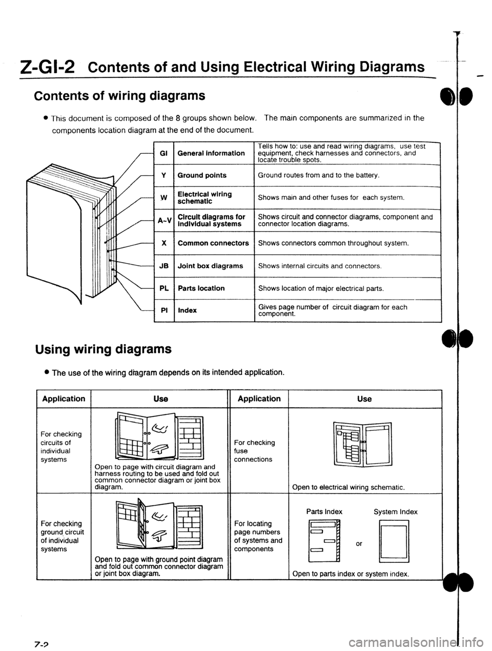
Contents of wiring diagrams
l This document is composed of the 8 groups shown below. The main components are summarized in the
components location diagram at the end of the document.
Tells how to: use and read wiring dragrams, use test
GI General information equipment, check harnesses and connectors, and
locate trouble spots.
Y Ground points Ground routes from and to the battery.
I
w
I Electrical wiring
schematic
I Shows main and other fuses for each system.
lndlvidual systems
I Shows circuit and connector diagrams, component and
connector location diagrams.
1
X
I Common connectors
I Shows connectors common throughout system.
I
JB Joint box diagrams Shows internal circuits and connectors.
PL Parts location Shows location of major electrical parts.
PI Index
I
I
Gives page number of circuit diagram for each
component.
Using wiring diagrams
l The use of the wiring diagram depends on its intended application. Application
For checking
circuits of
individual
systems
For checking
ground circuit
of individual
systems 7-3 Use
II Application
Open to page with circuit diagram and
harness routing to be used and fold out
common connector diagram or joint box
diagram. For checking
fuse
connections Use
Open to electrical wiring schematic.
Open to page with ground point diagram
and fold out common connector diagram
or joint box diagram. For locating
page numbers
of systems and
components Parts Index
H
Open to parts index or system index.
Page 1059 of 1164

I
E
,
1
I
i
t
1
I
!
!
I
t:
I.
1.
i
i
Reading Wiring Diagrams Z-Gl-3
Ground points
l This shows ground points of the harness.
CIGARETTE LIGHTER
INTERIOR LAMPS
H
I On vehicle
I Indication
I
To circuit The ground connection numbers in system circuit
diagrams correspond to those in the ground point
diagram.
Page 1060 of 1164

Z-Gl-4 Reading Wiring Diagrams
System circuit diagram/connector diagram
l These show the circuits for each system, from the power supply to the ground. The power supply side
is on the upper part of the page, the ground side on the lower part. The diagrams describe circuits with
the ignition switch off.
Below is an explanation of the various points in the diagram.
) Indicates operating conditions for switches.
The prefix letter indicates the system in which
:he connector is used.
JB: Joint box connections
X : Common connectors
A : Charging system/starting system
connectors
B : Engine control system connectors
C : Gauge control system connectors
D : Wiper system connectors
E : Lighting system connectors
F : Signal system connectors
G : Air-conditioning system connectors
H : Transmission control system
connectors
I : Interior lamp system connectors
J : Audio/radio connectors
K : Power window/power door lock system
connectors
L : Remote control mirror system
connectors
M : Sliding sunroof system connectors
N : Power steering/4-wheel steering
system connectors
0 : Anti-lock brake system connectors
P : Power seat/seat heater system
connectors
Cl : Auto cruise control system connectors
R : Auto adjusting suspension system
connectors
S : Passive shoulder belt control/air bag
system connectors
T : Others
Y : Ground connector
- .
1
\\‘
IGNITION SYSTEM l ENGINE CONTROL 9 harness ground is represented differently
:han a unit ground.
Types of grounds Symbol
Harness
I
-
-
-
-
‘“G:
si-
P
7:’
.I
I
I
.i
-
-
-
f
9
Tiii
zs
LL
a
EE
-