change time MAZDA PROTEGE 1992 Workshop Manual
[x] Cancel search | Manufacturer: MAZDA, Model Year: 1992, Model line: PROTEGE, Model: MAZDA PROTEGE 1992Pages: 1164, PDF Size: 81.9 MB
Page 37 of 1164
ENGINE TUNE-UP PROCEDURE Bl
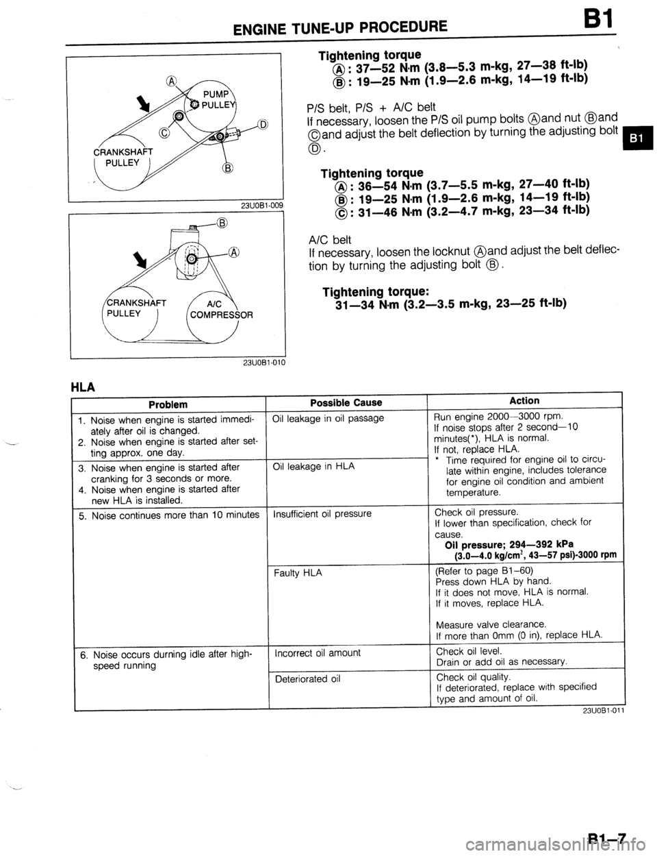
Tightening torque
@ : 37-52 N,m (3.8-5.3 m-kg, 27-38 ft-lb)
@ : 19-25 Nsm (1.9-2.6 m-kg, 14-19 ft-lb)
23UOBl-OC
P/S belt, P/S + A/C belt
If necessary, loosen the P/S oil pump bolts @and nut @and
Oand adjust the belt deflection by turning the adjusting bolt
0.
Tightening torque
@I : 36-54 N.m (3.7-5.5 m-kg, 27-40 ft-lb)
@ : 19-25 N#m (1.9-2.6 m-kg, 14-19 ft-lb)
0: 31-46 N-m (3.2-4.7 m-kg, 23-34 ft-lb)
A/C belt
If necessary, loosen the locknut @and adjust rhe belt deflec-
tion by turning the adjusting bolt @.
Tightening torque:
31-34 N-m (3.2-3.5 m-kg, 23-25 ft-lb)
1
HLA
Problem Possible Cause Action
1. Noise when engine is started immedi- Oil leakage in oil passage Run engine 2000-3000 rpm.
ately after oil is changed. If noise stops after 2 second-10
2. Noise when engine is started after set- minutes(*), HLA is normal.
ting approx. one day. If not, replace HLA.
3. Noise when engine is started after Oil leakage in HLA - * Time required for engine oil to circu-
cranking for 3 seconds or more. late within engine, includes tolerance
4. Noise when engine is started after for engine oil condition and ambient
new HLA is installed. temperature.
5. Noise continues more than 10 minutes Insufficient oil pressure Check oil pressure.
If lower than specification, check for
cause.
Oil pressure; 294-392 kPa
(3.0-4.0 kg/cm*, 43-57 psi)-3000 rpm
(Refer to page 81-60)
Press down HLA by hand.
If it does not move,. HLA is normal.
If it moves, replace HLA.
t
I
Measure valve clearance.
If more than Omm (0 in), replace HLA.
5. Noise occurs durning idle after high-
speed running Incorrect oil amount
Deteriorated oil Check oil level.
Drain or add oil as necessary.
Check oil quality.
If deteriorated, replace with specified
type and amount of oil.
23UOBl-01
Bl-7
Page 139 of 1164
ENGINE TUNE-UP PROCEDURE 92
23UOB2-OC
DRIVE PULLEY
I I
2311082.010
HLA
I Problem
1. Noise when engine is started immedi-
ately after oil is changed.
2. Noise when engine is started after set-
tina aporox. one dav.
3. Noise when engine is started after
cranking for 3 seconds or more.
4. Noise when engine is started after
new HLA is installed.
5. Noise continues more than 10 minutes
6. Noise occurs durning idle after high-
“”
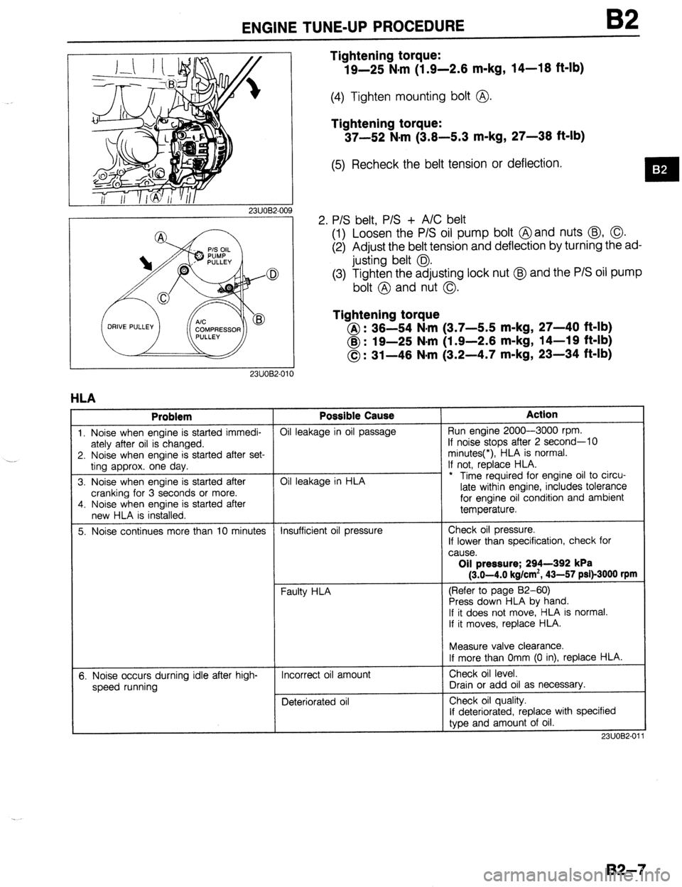
Tightening torque:
19-25 N.m (1.9-2.6 m-kg, 14-16 ft-lb)
(4) Tighten mounting bolt @.
Tightening torque:
37-52 N#rn (3.6-5.3 m-kg, 27-36 ft-lb)
(5) Recheck the belt tension or deflection.
2. P/S belt, P/S + A/C belt
(1) Loosen the P/S oil pump bolt @and nuts @, 0.
(2) Adjust the belt tension and deflection by turning the ad-
justing belt 0.
(3) Tighten the adjusting lock nut @J and the P/S oil pump
bolt @ and nut 0.
Tightening torque
@: 36-54 N-m (3.7-5.5 m-kg, 27-40 ft-lb)
@ : 19-25 N*m (1.9-2.6 m-kg, 14-19 ft-lb)
0: 31-46 N-m (3.2-4.7 m-kg, 23-34 ft-lb) Possible Cause
Oil leakage in oil passage
Oil leakage in HLA
Insufficient oil pressure
Faulty HLA
Incorrect oil amount
Deteriorated oil Action Run engine 2000-3000 rpm.
If noise stops after 2 second-10
minutes(*), HLA is normal.
If not, replace HLA.
* Time required for engine oil to circu-
late within engine, includes tolerance
for engine oil condition and ambient
temperature.
Check oil pressure.
If lower than specification, check for
cause. Oil pressure; 294-392 kPa
(3.0-4.0 kg/cm’, 43-57 psi)-3000 rpm
(Refer to page 82-60)
Press down HLA by hand.
If it does not move, HLA is normal.
If it moves, replace HLA.
Measure valve clearance.
If more than Omm (0 in), replace HLA.
Check oil level.
Drain or add oil as necessary.
Check oil quality.
If deteriorated, replace with specified
type and amount of oil.
2311082-01
B2-7
Page 293 of 1164
TROUBLESHOOTING GUIDE
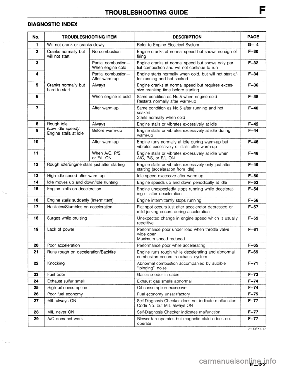
DIAGNOSTIC INDEX
No. TROUBLESHOOTING ITEM DESCRIPTION
1 Will not crank or cranks slowly Refer to Engine Electrical System PAGE
G- 4
Engine cranks at normal speed but shows no sign of 1 F-30
Engine cranks at normal speed but shows only par-
I
tial combustion and will not continue to run
Engine starts normally when cold, but will not start af-
After warm-up
5 Cranks normally but
Always
hard to start Engine cranks at normal speed but requires exces-
sive cranking time before starting F-36
F-38
I----
F-40 Same condition as No.5 when engine cold
Restarts normally after warm-up
Same cond;ion as No.5 after running and hot
soaked
Starts normally when cold
8
H
Rough idle
9 (Low idle speed)/
Engine stalls at idle Enaine stalls or vibrates excessivelv at idle
Engine stalls or vibrates excessively at idle during
warm-up 1 F-42
F-44
Engine runs normally at idle during warm-up but
vibrates excessively or stalls after warm-up
Engine stalls or vibrates excessively at idle when
A/C, P/S, or E/L ON F-46
F-46
starting (acceleration from idle)
l---- Engine stalls or vibrates excessively only just after
Idle speed excessive after warm-up 1 F-50 F-49 12 Rough idle/Engine stalls just after starting
13 High idle speed after warm-up
1 14 1 Idle moves up and down/Idle hunting Engine speeds up and down periodically at idle
1 F-52
I l5 I Engine stalls on deceleration
Engine unexpectedly stops running while decelerat-
ing or after deceleration F-54
Engine intermittently stops running
Flat spot occurs just after accelerator depressed or
mild jerkrng occurs during acceleration
Unexpected change in engine speed which is usually
repetitive F-56
F-57
F-59 16 Engine stalls suddenly (Intermittent)
17 Hesitates/Stumbles on acceleration
1 18 1 Surges while cruising
19
I I
Lack of power Performance poor under load when throttle valve F-61
wide open
Maximum speed reduced
Performance poor-while accelerating
-I- F-65 20 Poor acceleration
21 Runs rough on deceleration/Backfire Engine runs rough while decelerating and abnormal
combustion occurs in exhaust system F-69
Abnormal combustion accompanied by audible
“pinging” noise
Gasoline odor in cabin 22 Knocking
23 Fuel odor
24 Exhaust sulfur smell
26 High oil consumption Exhaust gas smells abnormal
Oil consumption excessive
Fuel economy unsatisfactory 1 26 1 Poor fuel economy 1 F-75
Self-Diagnosis Checker does not indicate malfunction
23UOFX~O’
F-27
Page 536 of 1164
Jl TRANSAXLE
I I 03UOJ2-089
03UOJ2-091 3
03UOJ2-09
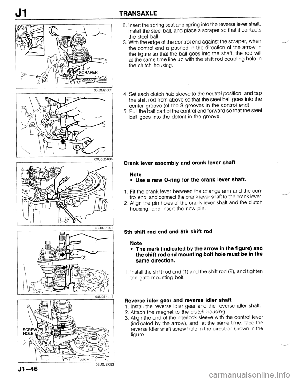
2. Insert the spring seat and spring into the reverse lever shaft,
install the steel ball, and place a scraper so that it contacts
the steel ball.
3. With the edge of the control end against the scraper, when
the control end is pushed in the direction of the arrow in
the figure so that the ball goes into the shaft, the rod will
at the same time line up with the shift rod coupling hole in
the clutch housing.
4. Set each clutch hub sleeve to the neutral position, and tap
the shift rod from above so that the steel ball goes into the
center groove (of the 3 grooves in the control end).
5. Pull the ball part of the control end forward so that the steel
ball goes into the detent in the groove.
Crank lever assembly and crank lever shaft
Note
l Use a new O-ring for the crank lever shaft.
1. Fit the crank lever between the change arm and the con-
trol end, and connect the crank lever shaft to the crank lever.
2. Align the pin holes of the crank lever shaft and the clutch
housing, and insert the new pin. -’
5th shift rod end and 5th shift rod
Note
l The mark (indicated by the arrow in the figure) and
the shift rod end mounting bolt hole must be in the
same direction.
1. Install the shift rod end (1) and the shift rod (2), and tighten
the gate mounting bolt.
Reverse idler gear and reverse idler shaft
1. Install the reverse idler gear and the reverse idler shaft.
2. Attach the magnet to the clutch housing.
3. Align the end of the interlock sleeve with the control lever
(indicated by the arrow), and, at the same time, face the
reverse idler shaft screw hole in the direction shown in the
figure.
Jl-46
Page 586 of 1164
J2 TRANSAXLE
03UOJ2-08
03UOJ2-09(
03UOJ2-09’
J2-38
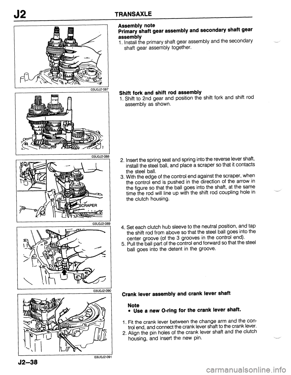
Assembly note
Primary shaft gear assembly and secondary shaft gear
assembly
1. Install the primary shaft gear assembly and the secondary
shaft gear assembly together.
Shift fork and shift rod assembly
1. Shift to 2nd gear and position the shift fork and shift rod
assembly as shown.
2. Insert the spring seat and spring into the reverse lever shaft,
install the steel ball, and place a scraper so that it contacts
the steel ball.
3. With the edge of the control end against the scraper, when
the control end is pushed in the direction of the arrow in
the figure so that the ball goes into the shaft, at the same
time the rod will line up with the shift rod coupling hole in
the clutch housing.
4. Set each clutch hub sleeve to the neutral position, and tap
the shift rod from above so that the steel ball goes into the
center groove (of the 3 grooves in the control end).
5. Pull the ball part of the control end forward so that the steel
ball goes into the detent in the groove.
Crank lever assembly and crank lever shaft
Note
l Use a new O-ring for the crank lever shaft.
1. Fit the crank lever between the change arm and the con-
trol end, and connect the crank lever shaft to the crank lever.
2. Align the pin holes of the crank lever shaft and the clutch
housing, and insert the new pin.
Page 679 of 1164
CONVENTIONALBRAKESYSTEM P
1 SUOPX-001
03UOPX-03
0
o3uoPx-os
0
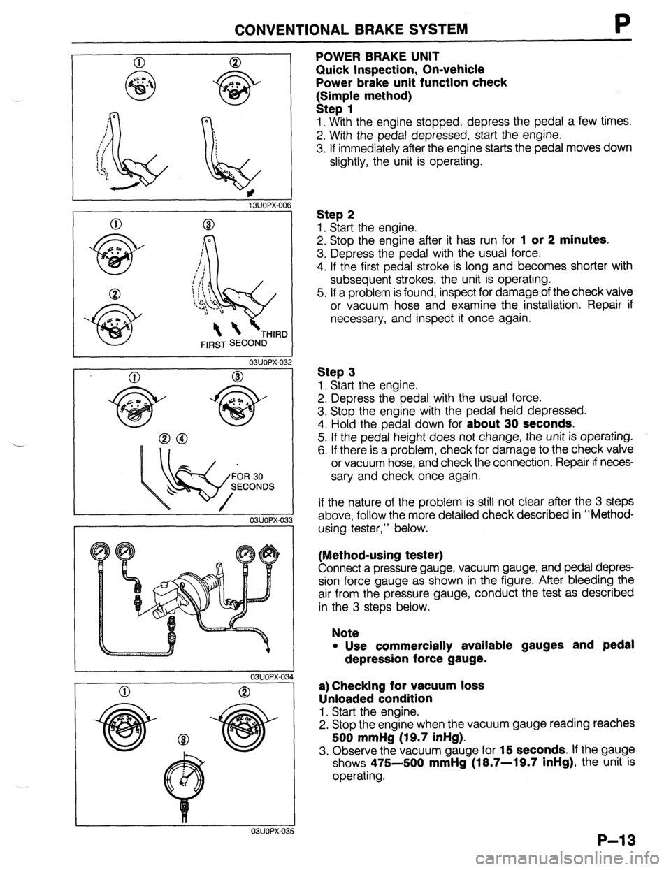
POWER BRAKE UNIT
Quick Inspection, On-vehicle
Power brake unit function check
k:;;p{e method)
1. With the engine stopped, depress the pedal a few times.
2. With the pedal depressed, start the engine.
3. If immediately after the engine starts the pedal moves down
slightly, the unit is operating.
Step 2
1. Start the engine.
2. Stop the engine after it has run for
1 or 2 minutes.
3. Depress the pedal with the usual force.
4. If the first pedal stroke is long and becomes shorter with
subsequent strokes, the unit is operating.
5. If a problem is found, inspect for damage of the check valve
or vacuum hose and examine the installation. Repair if
necessary, and inspect it once again.
Step 3
1. Start the engine.
2. Depress the pedal with the usual force.
3. Stop the engine with the pedal held depressed.
4. Hold the pedal down for
about 30 seconds.
5. If the pedal height does not change, the unit is operating.
6. If there is a problem, check for damage to the check valve
or vacuum hose, and check the connection. Repair if neces-
sary and check once again.
If the nature of the problem is still not clear after the 3 steps
above, follow the more detailed check described in “Method-
using tester,” below.
(Method-using tester)
Connect a pressure gauge, vacuum gauge, and pedal depres-
sion force gauge as shown in the figure. After bleeding the
air from the pressure gauge, conduct the test as described
in the 3 steps below.
Note
l Use commercially available gauges and pedal
depression force gauge.
a) Checking for vacuum loss
Unloaded condition
1. Start the engine.
2. Stop the engine when the vacuum gauge reading reaches
500 mmHg (19.7 inHg).
3. Observe the vacuum gauge for 15 seconds. If the gauge
shows 475-500
mmHg (18.7-19.7 inHg), the unit is
operating.
P-13
Page 719 of 1164
FRONT SUSPENSION (STRUT)
R
03UORX-022
.
.
H 03UOAX-02:
03UORX-02r
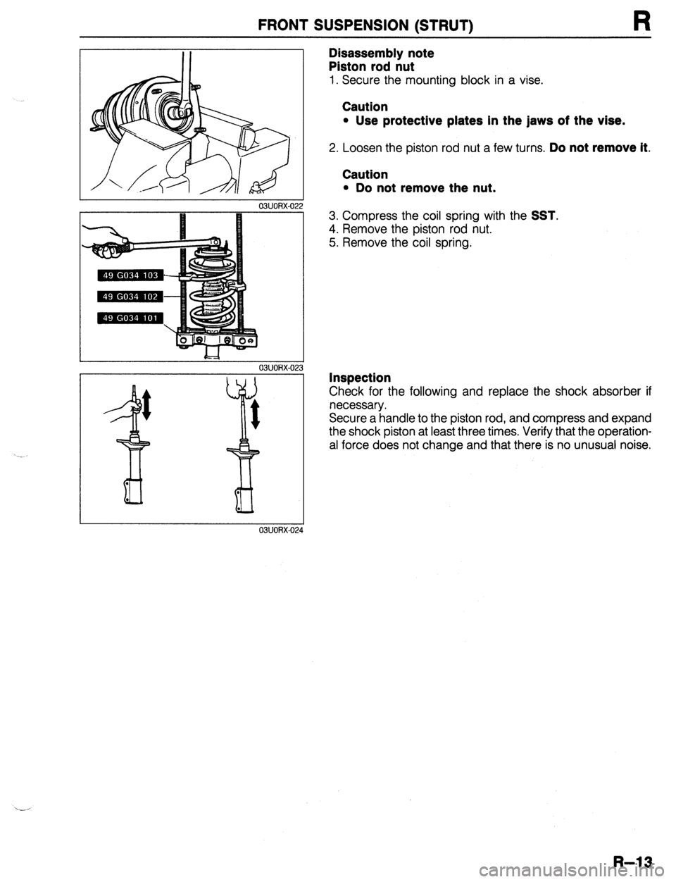
Disassembly note
Piston rod nut
1. Secure the mounting block in a vise.
Caution
l Use protective plates in the jaws of the vise.
2. Loosen the piston rod nut a few turns. Do not remove it.
Caution
l Do not remove the nut.
3. Compress the coil spring with the SST.
4. Remove the piston rod nut.
5. Remove the coil spring.
Inspection
Check for the following and replace the shock absorber if
necessary.
Secure a handle to the piston rod, and compress and expand
the shock piston at least three times. Verify that the operation-
al force does not change and that there is no unusual noise.
R-13
Page 729 of 1164
REAR SUSPENSION (STRUT)
03UORX-04
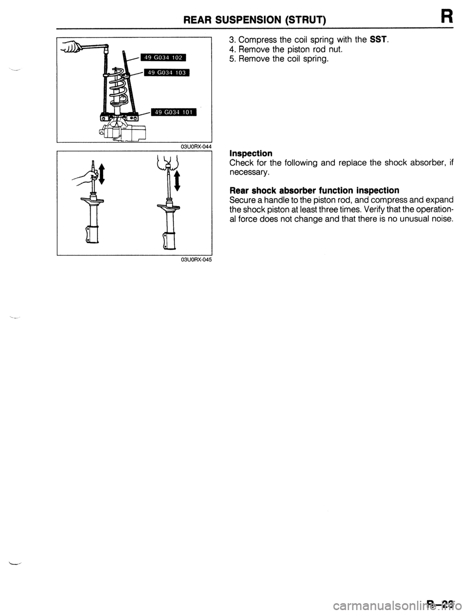
3. Compress the coil spring with the SST.
4. Remove the piston rod nut.
5. Remove the coil spring.
Inspection
Check for the following and replace the shock absorber, if
necessary.
Rear shock absorber function inspection
Secure a handle to the piston rod, and compress and expand
the shock piston at least three times, Verify that the operation-
al force does not change and that there is no unusual noise.
R-23
Page 1054 of 1164
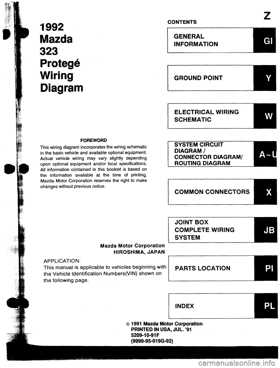
1992
Mazda
323
Protege
Wiring
Diagram
FOREWORD
This wiring diagram incorporates the wiring schematic
in the basic vehicle and available optional equipment.
Actual vehicle wiring may vary slightly depending
upon optional equipment and/or focal specifications.
All information contained in this booklet is based on
the information available at the time of printing,
Mazda Motor Corporation reserves the right to make
changes without previous notice.
Mazda Motor Corporation
HIROSHIMA, JAPAN
APPLICATION:
This manual is applicable to vehicles beginning with
the Vehicle Identification Numbers(VIN) shown on
the following page.
z CONTENTS
o 1991 Mazda Motor Corporation
PRINTED IN USA, JUL. ‘91
5209-l O-91 F
E (9999-95-0196-92)