torque MAZDA PROTEGE 1992 Workshop Manual
[x] Cancel search | Manufacturer: MAZDA, Model Year: 1992, Model line: PROTEGE, Model: MAZDA PROTEGE 1992Pages: 1164, PDF Size: 81.9 MB
Page 742 of 1164
HOOD
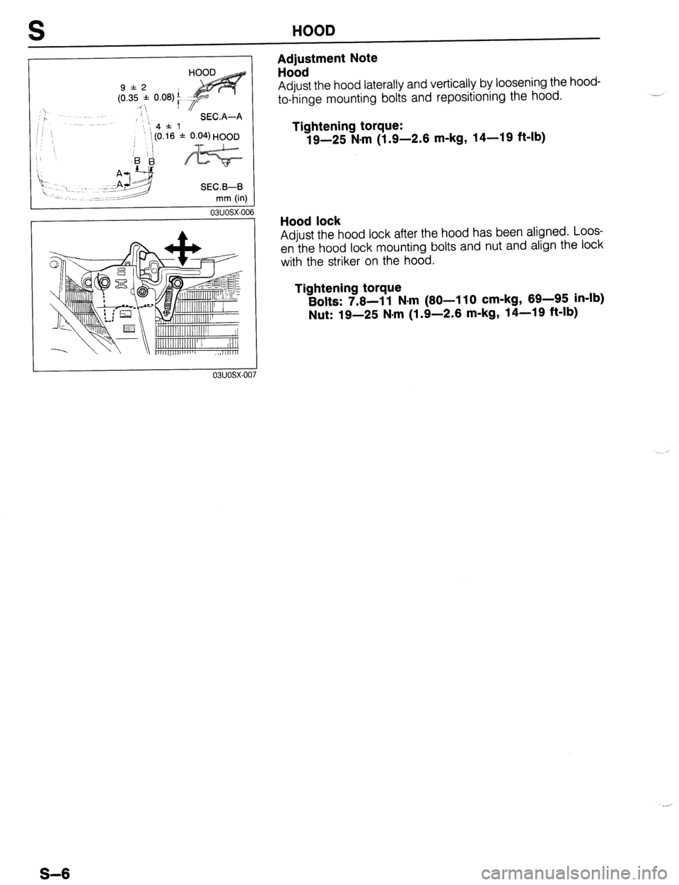
Adjustment Note
Hood
9*2
(0.35 * 0.08)’
“ I
>
P SEC.A-A
;; ‘, Adjust the hood laterally and vertically by loosening the hood-
to-hinge mounting bolts and repositioning the hood. .-
Tightening torque:
19-25 N.m (1.9-2.6 m-kg, 14-19 ft-lb)
ii1
‘ -~ 1. J -I SEC.B-B
03uosx-oc 16
Hood lock
Adjust the hood lock after the hood has been aligned. Loos-
en the hood lock mounting bolts and nut and align the lock
with the striker on the hood.
Tightening torque
Bolts: 7.8-l 1 N-m (80-I 10 cm-kg, 69-95 in-lb)
Nut: 19-25 N,rn (1.9-2.6 m-kg, 14-19 ft-lb)
S-6
Page 745 of 1164
FRONT DOOR S
03uosx-01’
PROTEGk 6
f 1.5 (0.24 f 0.06)
HATCHBACK: 6.3
f 1.5 (0.25 f 0.06
mm (in)
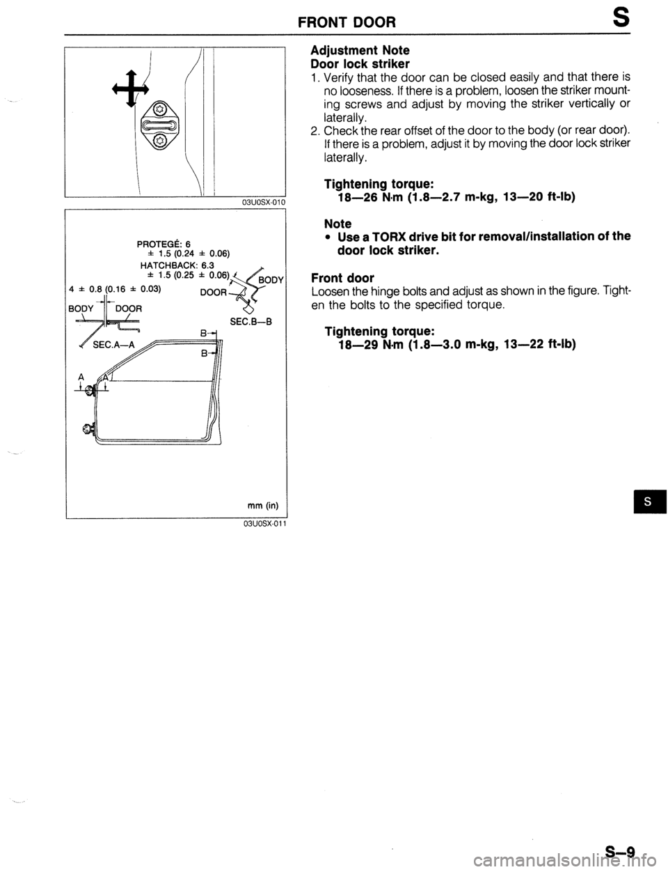
Adjustment Note
Door lock striker
1. Verify that the door can be closed easily and that there is
no looseness. If there is a problem, loosen the striker mount-
ing screws and adjust by moving the striker vertically or
laterally.
2. Check the rear offset of the door to the body (or rear door).
If there is a problem, adjust it by moving the door lock striker
laterally.
Tightening torque:
18-28 N-m (1.8-2.7 m-kg, 13-20 ft-lb)
Note
l Use a TORX drive bit for removal/installation of the
door lock striker.
Front door
Loosen the hinge bolts and adjust as shown in the figure. Tight-
en the bolts to the specified torque.
Tightening torque:
18-29 N-m (1.8-3.0 m-kg, 13-22 ft-lb)
s-9
Page 752 of 1164
S REAR DOOR
4 f 0.8 (0.16 f 0.03)
OR (FRONT)
-c1 A4 SEC.A-A
mm (in)
03uosx-0’
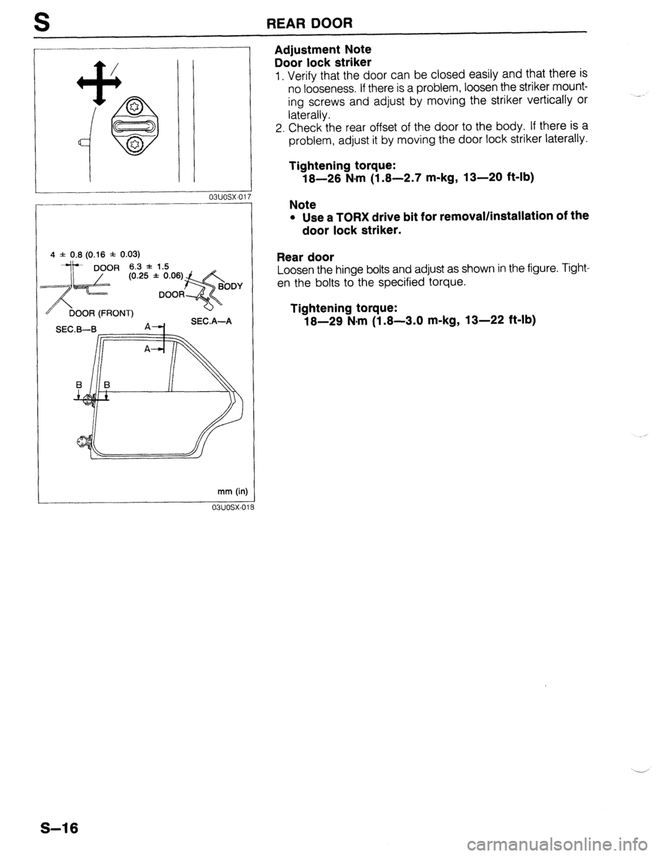
Adjustment Note
Door lock striker
1. Verify that the door can be closed easily and that there is
no looseness. If there is a problem, loosen the striker mount-
ing screws and adjust by moving the striker vertically or
laterally.
2. Check the rear offset of the door to the body. If there is a
problem, adjust it by moving the door lock striker laterally.
Tightening torque:
18-26 N.m (1.8-2.7 m-kg, 13-20 ft-lb)
Note
l Use a TORX drive bit for removal/installation of the
door lock striker.
Rear door
Loosen the hinge bolts and adjust as shown in the figure. Tight-
en the bolts to the specified torque.
Tightening torque:
18-29 N-m (1.8-3.0 m-kg, 13-22 ft-lb)
S-16
Page 757 of 1164
REAR HATCH S
7 f 1.5 (0.28 f 0.06) 6 f 0.8
(0.24 * 0.03)
9 SECA-A R
mm (i..,
03UOSX-02
---i-
----:.
03uosx-oi
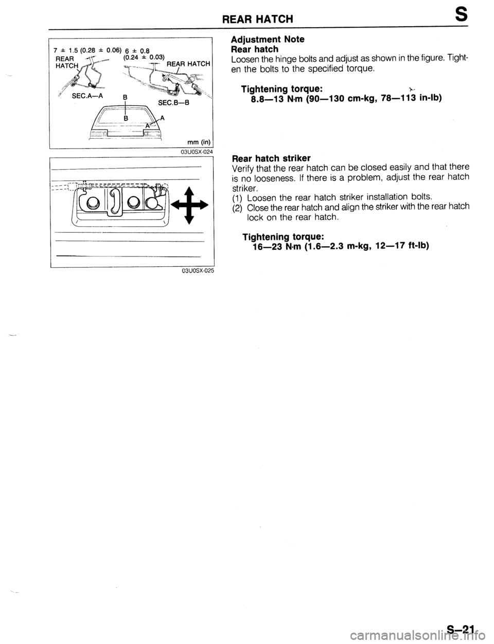
Adjustment Note
Rear hatch
Loosen the hinge bolts and adjust as shown in the figure. Tight-
en the bolts to the specified torque.
Tightening torque:
8.8-13 N*m (90-l 30 cm-kg, 78-l 1: in-lb)
Rear hatch striker
Verify that the rear hatch can be closed easily and that there
is no looseness. If there is a problem, adjust the rear hatch
striker.
(1) Loosen the rear hatch striker installation bolts.
(2) Close the rear hatch and align the striker with the rear hatch
lock on the rear hatch.
Tightening torque:
18-23 N*m (1.6-2.3 m-kg, 12-17 ft-lb)
s-21
Page 770 of 1164
S TRUNK LID
03uosx-04’
HINGE (L.H.)
RIGHT SPRING -1
I
,i I
II
1
k
TRUNK LID
TRUNK LID
SEC.B--8
6 * 1.5 (0.31 * 0.06)
SECA-A mm (in)
03uosx-01
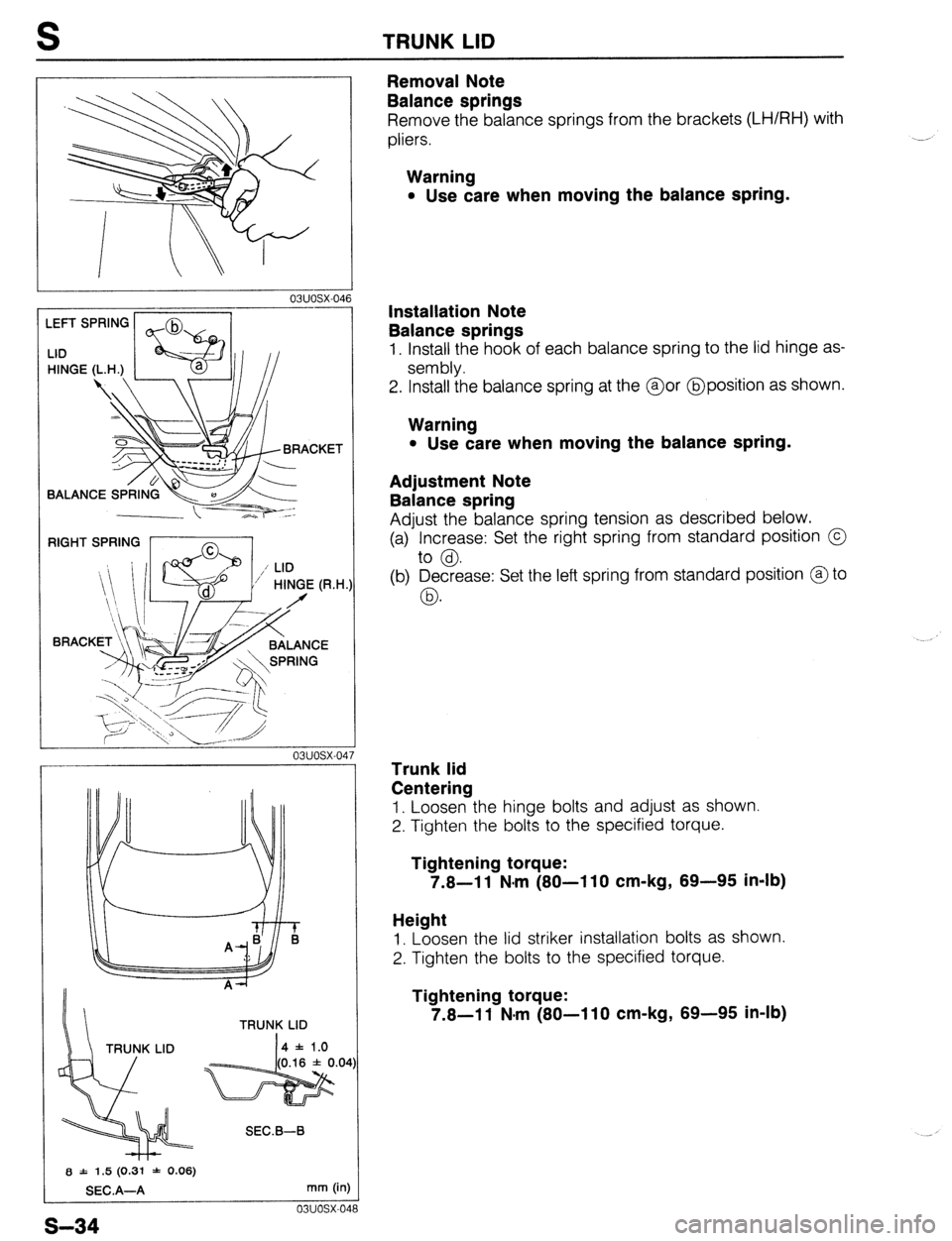
Removal Note
Balance springs
Remove the balance springs from the brackets (LH/RH) with
pliers.
Warning
l Use care when moving the balance spring.
Installation Note
Balance springs
1. Install the hook of each balance spring to the lid hinge as-
sembly.
2. Install the balance spring at the @or @position as shown.
Warning
l Use care when moving the balance spring.
Adjustment Note
Balance spring
Adjust the balance spring tension as described below.
(a) Increase: Set the right spring from standard position @
to @.
(b) Decrease: Set the left spring from standard position @to
03.
Trunk lid
Centering
1. Loosen the hinge bolts and adjust as shown.
2. Tighten the bolts to the specified torque.
Tightening torque:
7.8-l 1 N-m (80-l 10 cm-kg, 89-95 in-lb)
Height
1. Loosen the lid striker installation bolts as shown.
2. Tighten the bolts to the specified torque.
Tightening torque:
7.8-11 N-m (80-110 cm-kg, 89-95 in-lb)
s-34
Page 809 of 1164
WINDSHIELD WIPER AND WASHER S
ALIGNMEhT MARK
23UOSX.023
MOLDING END FACE
!6-
1.10-1.26)
/ COWL GRILLE END FACE
mm (in
o3uosx-l2!
tATCHBACK
-L I COWL dRlLLE
mm (in:
03uosx-131
Removal Note / Installation Note
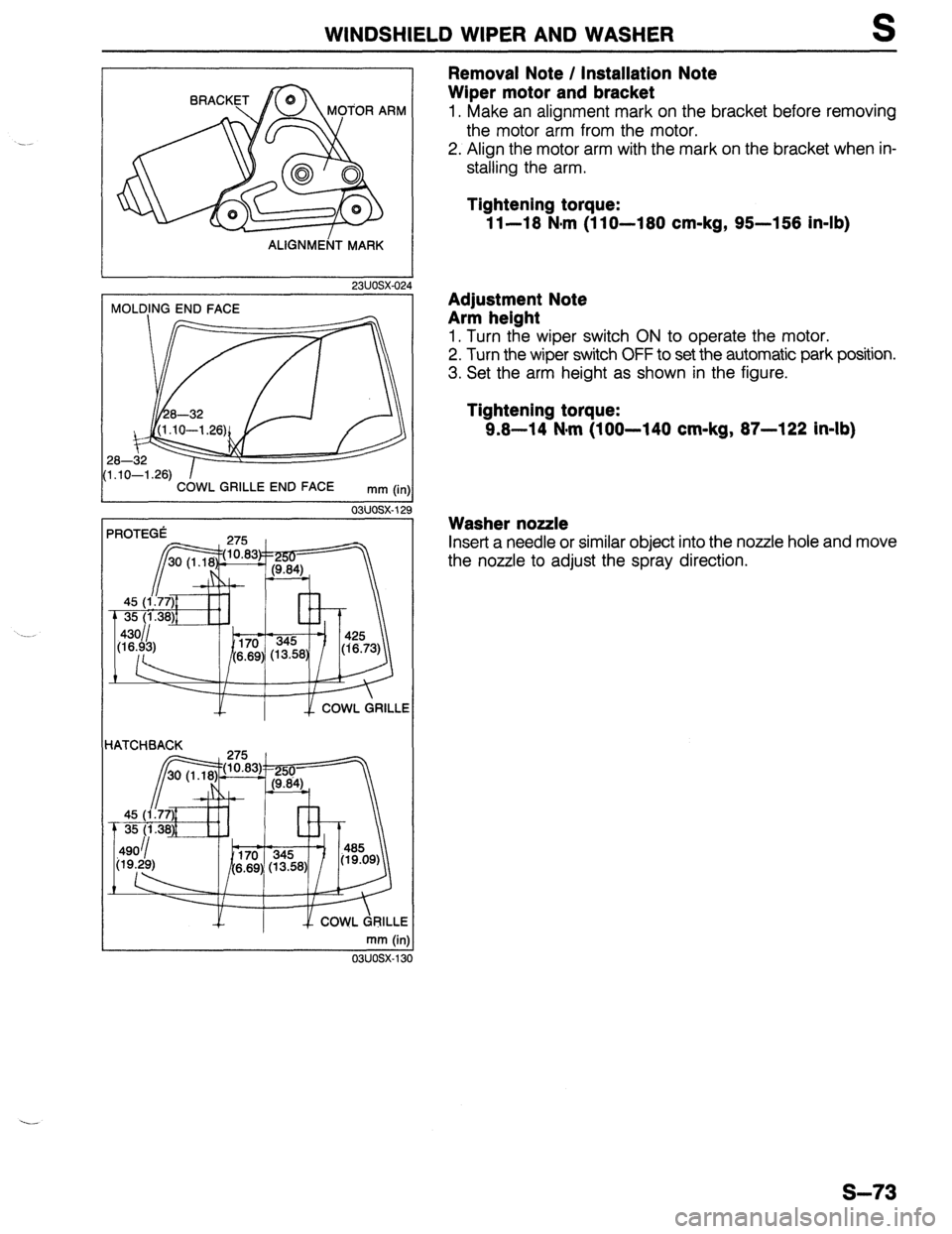
Wiper motor and bracket
1. Make an alignment mark on the bracket before removing
the motor arm from the motor.
2. Align the motor arm with the mark on the bracket when in-
stalling the arm.
Tightening torque:
1 l-18 N,m (1 lo-180 cm-kg, 95-158 in-lb)
Adjustment Note
Arm helght
1. Turn the wiper switch ON to operate the motor.
2. Turn the wiper switch OFF to set the automatic park position.
3. Set the arm height as shown in the figure.
Tightening torque:
9.8-14 N-m (100-140 cm-kg, 87-122 in-lb)
Washer nozzle
Insert a needle or similar object into the nozzle hole and move
the nozzle to adjust the spray direction.
s-73
Page 815 of 1164
REAR WIPER AND WASHER S
Wiper
Washer
1. Rear hatch lower trim
7. Trunk end trim
Removal / Installation . . . . . . . . . . . . . . . . page S-
98 Removal / Installation . . . . . . . . . . . . . . . . page
S- 98
2. Wiper arm cover 8. Trunk side cover
3. Rear wiper arm and blade Removal / Installation . . . . . . . . . . . . . . . . page S-
98
Adjustment
Note . . . . . . . . . . . . . . . . . . . . . . . page S- 79 9. Trunk side trim
4. Seal cap Removal / Installation . . . . . . . . . . . . . . . . page S-
98
5. Outer bushing 10. Rear header trim
6. Rear wiper motor Removal / Installation . . . . . . . . . . . . . . . . page S- 98
Inspection .,, ., . . . . . . . . . . . . . . . . . . . . . . . . . . . .
page S- 77 11. Rear seat belt upper anchor
Removal / Installation . . . . . . . . . . . . . . . . page S-l 01
12. C-pillar trim
Removal / Installation . . . . . . . . . . . . . . . . page S-
98
13. Washer tank assembly
a. Washer tank
b. Washer motor
Inspection . . . . . . . . . . . . . . . . . . . . . . . . . . . . . . . . .
page S- 77
14. Washer nozzle
Adjustment Note . . . . . . . . . . . . . . . . . . . . . . . page S-
79
15. Washer pipe
23UOSX-032
REAR WINDOW MOLDING
mm (in)
03uosx-14
REAR WINDQW MOLDING I
mm (in
03uosx-14
Adjustment Note
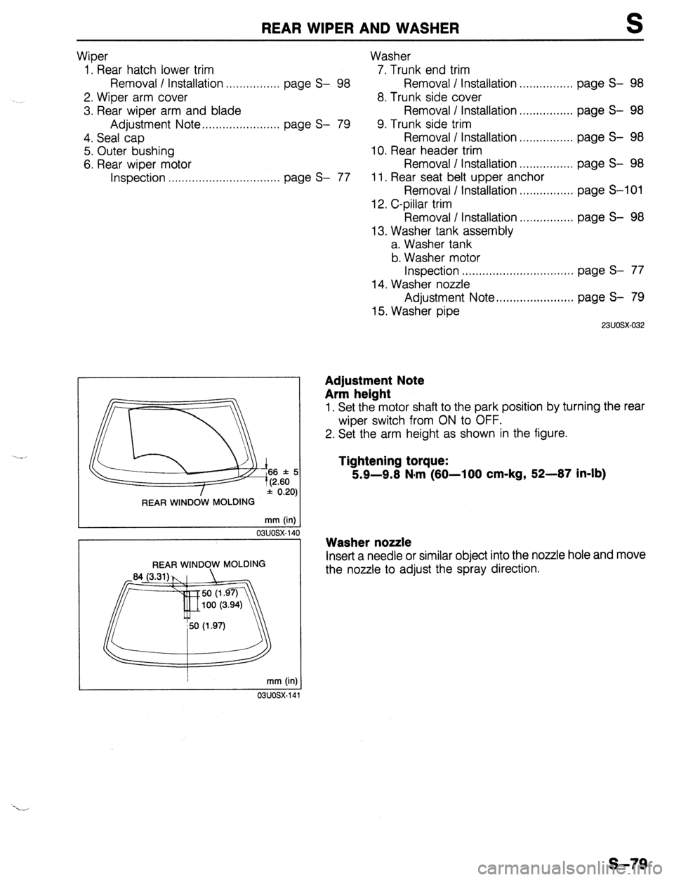
Arm height
1. Set the motor shaft to the park position by turning the rear
wiper switch from ON to OFF.
2. Set the arm height as shown in the figure.
Tightening torque:
5.9-9.8 N*m (80-100 cm-kg, 52-87 in-lb)
Washer nozzle
Inset-t a needle or similar object into the nozzle hole and move
the nozzle to adjust the spray direction.
s-79
Page 824 of 1164
S SLIDING SUNROOF
SET--PLATE
5.8 f 0.3 (0.23 f 0.01)
D5.8U.3& (0.23 f 0.01
SEC. A-A
13uosx.030 mm (in)
03UOSX-16
TORQUE ADJUSTING NUT
PAWL WASHER
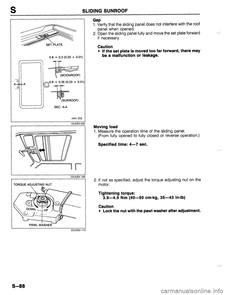
Gap 1, Verify that the sliding panel does not interfere with the roof
panel when opened.
2. Open the sliding panel fully and move the set plate forward
if necessary.
Caution
l If the set plate is moved too far forward, there may
be a malfunction or leakage.
Moving load
1. Measure the operation time of the sliding panel.
(From fully opened to fully closed or reverse operation.)
Specified time: 4-7 sec.
2. If not as specified, adjust the torque adjusting nut on the
motor.
Tightening torque:
3.9-4.9 N-m (40-50 cm-kg, 35-43 in-lb)
Caution
l Lock the nut with the paw1 washer after adjustment.
Page 972 of 1164
U TROUBLESHOOTING GUIDE
Case 1: Insufficient refrigerant
Measured pressure
Low-pressure side: Less than 78.5 kPa (0.8 kg/cm2, 11.4 psi)
High-pressure side: 785-883 kPa (8-9 kg/cm2, 114-128 psi)
Condition
l Outlet air from vents not cold.
l Bubbles seen in sight glass.
Step 1
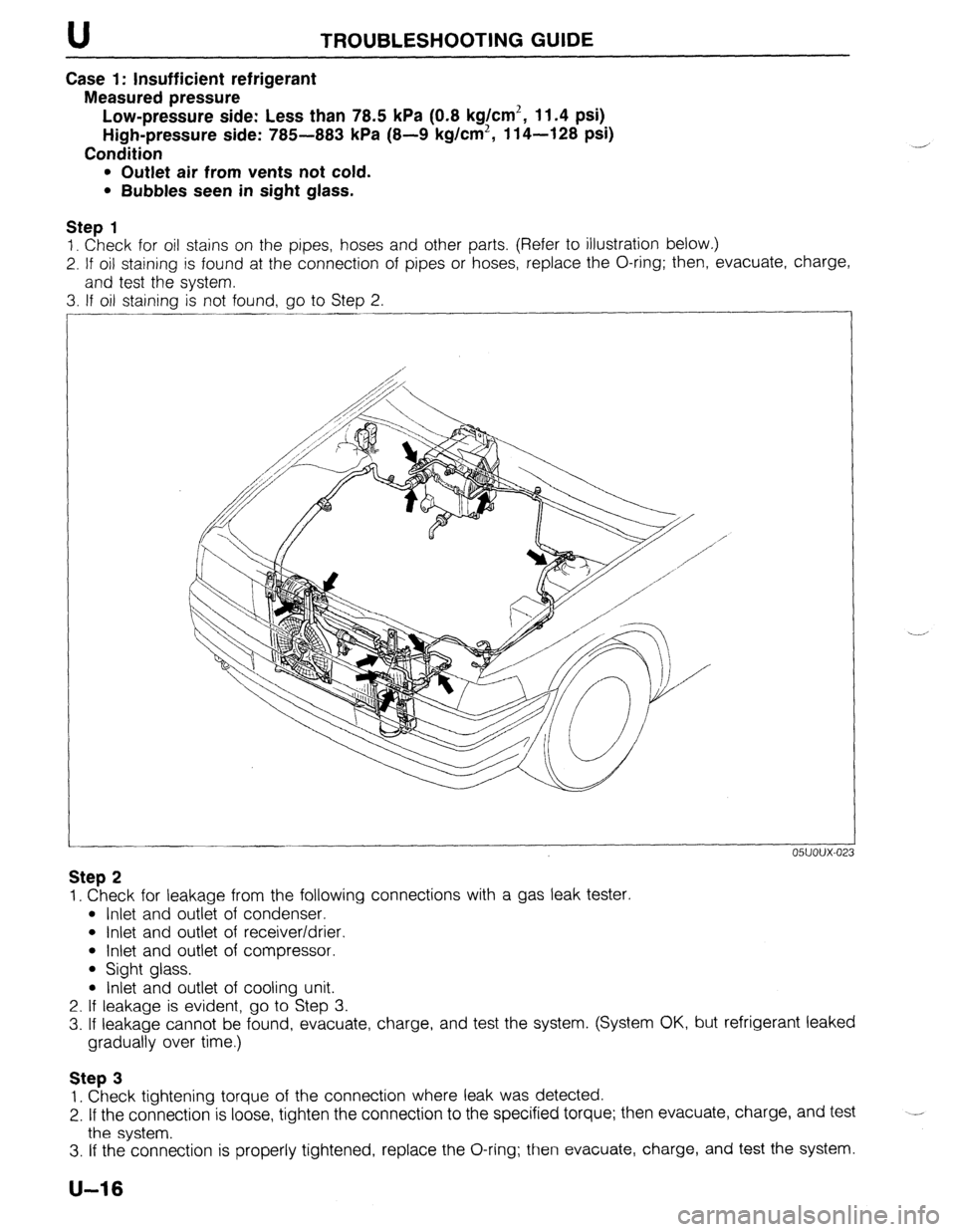
1. Check for oil stains on the pipes, hoses and other parts, (Refer to illustration below.)
2. If oil staining is found at the connection of pipes or hoses, replace the O-ring; then, evacuate, charge,
and test the system.
3. If oil staining is not found, go to Step 2.
05UOUX-02
Step 2
1. Check for leakage from the following connections with a gas leak tester.
l Inlet and outlet of condenser.
l Inlet and outlet of receiver/drier.
l Inlet and outlet of compressor.
l Sight glass.
l Inlet and outlet of cooling unit.
2. If leakage is evident, go to Step 3.
3. If leakage cannot be found, evacuate, charge, and test the system. (System OK, but refrigerant leaked
gradually over time.)
Step 3
1. Check tightening torque of the connection where leak was detected.
2. If the connection is loose, tighten the connection to the specified torque; then evacuate, charge, and test
the system. --
3. If the connection is properly tightened, replace the O-ring; then evacuate, charge, and test the system.
U-16
Page 990 of 1164
ENGINE sro~i32 U
Leak test
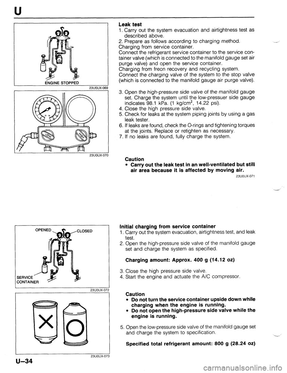
1. Carry out the system evacuation and airtightness test as
described above.
2. Prepare as follows according to charging method.
Charging from service container.
Connect the refrigerant service container to the service con-
tainer valve (which is connected to the manifold gauge set air
purge valve) and open the service container.
Charging from freon recovery and recycling system.
Connect the charging valve of the system to the stop valve
(which is connected to the manifold gauge air purge valve).
23UOUX-06
23UOUX-070
I 23UOUX-072
I
80 x 0
23UOUX-07
u-34
3
3. Open the high-pressure side valve of the manifold gauge
set. Charge the system until the low-pressuer side gauge
indicates 98.1 kPa. (1 kg/cm*, 14.22 psi).
4. Close the high pressure side valve.
5. Check for leaks at the system piping joints by using a gas
leak tester.
6. If leaks are found, check the O-rings and tightening torques
at the joints. Replace or retighten as necessary.
7. If no leaks are found, fully charge the system.
Caution
l Carry out the leak test in an well-ventilated but still
air area because it is affected by moving air.
23UOUX-071
Initial charging from service container
1. Carry out the system evacuation, airtightness test, and leak
test.
2. Open the high-pressure side valve of the manifold gauge
set and charge the system as specified.
Charging amount: Approx. 400 g (14.12 oz)
3. Close the high pressure side valve.
4. Start the engine and actuate the A/C compressor.
Caution
l Do not turn the service container upside down while
charging when the engine is running.
l Do not open the high-pressure side valve while the
engine is running.
5. Open the low-pressure side valve of the manifold gauge set
and charge the system to specification.
Specified total refrigerant amount: 800 g (28.24 oz) -.