ECU MAZDA PROTEGE 1992 User Guide
[x] Cancel search | Manufacturer: MAZDA, Model Year: 1992, Model line: PROTEGE, Model: MAZDA PROTEGE 1992Pages: 1164, PDF Size: 81.9 MB
Page 207 of 1164
ASSEMBLY 82
03UOB2-09
03UOB2-094
-
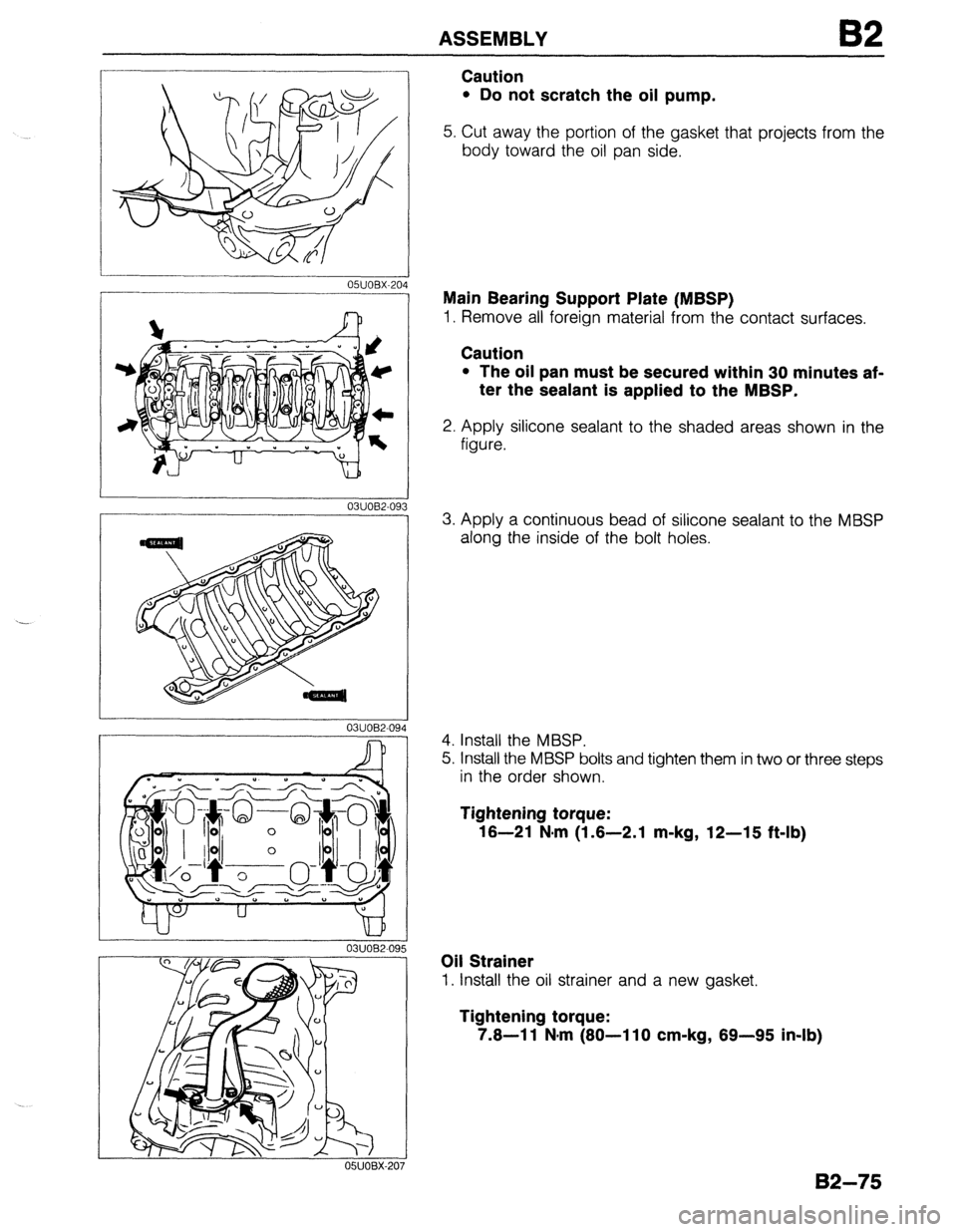
Caution
l Do not scratch the oil pump.
5. Cut away the portion of the gasket that projects from the
body toward the oil pan side.
Main Bearing Support Plate (MBSP)
1. Remove all foreign material from the contact surfaces.
Caution
l The oil pan must be secured within 30 minutes af-
ter the sealant is applied to the MBSP.
2. Apply silicone sealant to the shaded areas shown in the
figure.
3. Apply a continuous bead of silicone sealant to the MBSP
along the inside of the bolt holes.
4. Install the MBSP.
5. Install the MBSP bolts and tighten them in two or three steps
in the order shown.
Tightening torque:
16-21 N,m (1.6-2.1 m-kg, 12-15 ft-lb)
Oil Strainer
1. Install the oil strainer and a new gasket.
Tightening torque:
7.6-l 1 N-m (80-l 10 cm-kg, 89-95 in-lb)
B2-75
Page 216 of 1164

B2 ASSEMBLY
TIMING BELT
Torque Specifications
7.6-11 N:m
(60-l 10 cm-kg,
69-95 in-lb) \
-kg, 69-95 in-lb)
37-52
(3.8-5.3, 27-38)
157-167 (16-17, 116-123)
?.a--11 N-m
(60-110 cm-kg, 69-95 in-lb) /
12-17 (1.25-1.76, 9-13)
N-m (m-kg, ft-it
03UOB2.1
Idler
1. Install the idler.
Tightening torque:
37-52 N.m (3.8-5.3 m-kg, 27-38 ft-lb)
Tensioner and Tensioner Spring
1. Install the tensioner and the tensioner spring.
2. Temporarily secure the tensioner with the spring fully ex-
tended.
-’
o5uoBx-229
02-84
Page 227 of 1164

INSTALLATION B2
Step 2
Warning
l Be sure the vehicle is securely supported on Safety stands.
Torque Specifications
‘4-l 03
‘.5-10.5, 54-76)
37-52 (3.8-5.3, 27-38)
/
37-52 (3.8-5.3, 27-38)
64-89 (6.5-9.1, 47-66) 64-89 (6.5-9.1, 47-66)
N.m (m-kg, ft-II
OWOBX-21
Engine mount member (ATX)
1. Install the engine mount member.
Tightening torque:
64-89 N*m (6.5-9.1 m-kg, 47-66 ft-lb)
I I 03UOB2-130 1132-95
Page 229 of 1164

INSTALLATION
Step 3
Torque Specifications
16-23 (1.6-2.3, 12-17) 6.9-9.8 N.m (70-100 cm-kg, 61-87 in-lb)
I
m- ,,
// / 31-46 (3.2-4.7, 23-34)
ATX
Y
16-23 (1.6-2.3, 12-17) I 37-52 (3.8-5.3, 27-38) \/r-]z$/ 43-59 (4.4-6.0, 31-43)
COTTER PIN, NEW
/ 31-46 (3.2-4.7. 23-34) 42-67 (4.3-5.8, 31-42)
-_ ..------_ N.m (m-kg, R-lb)
no, Inor, 1.3
L 03UOB2 131
I 0311082-13.
Driveshaft
1. Apply grease to the end of the driveshaft.
Caution
l When installing the driveshaft, be careful not to
damage the oil seal.
l After installation, pull the front hub outward to con-
firm that the driveshaft is securely held by the clip.
2. Install the driveshaft and a new clip.
3. Install the lower arm ball-joint to the knuckle; then tighten
the lock nut.
Tightening torque:
43-59 N-m (4.4-6-O m-kg, 31-43 ft-lb)
4. Install the joint shaft.
5. Tighten the bolts in the order shown.
Tightening torque:
42-62 N-m (4.3-6.3 m-kg, 31-46 ft-lb)
82-97
Page 245 of 1164
OIL PAN
BPSOHCANDDOHC
D
I. Remove the oil pan mounting bolts. .-_-__------- BPSOHCANDDOHC
23UODX-007
MAIN BEARING SUPPORT PLATE (MBSP)
! 03UODX-021
MAIN BEARING SUPPORT PLATE (MBSP)
‘OLD SEALANT ---1_1
OBUODX-0: !2
Caution
l Do not force a prying tool between the cylinder
block and the oil pan, which may damage the con-
tact surfaces.
l Do not damage or scratch the contact surfaces
when removing the old sealant.
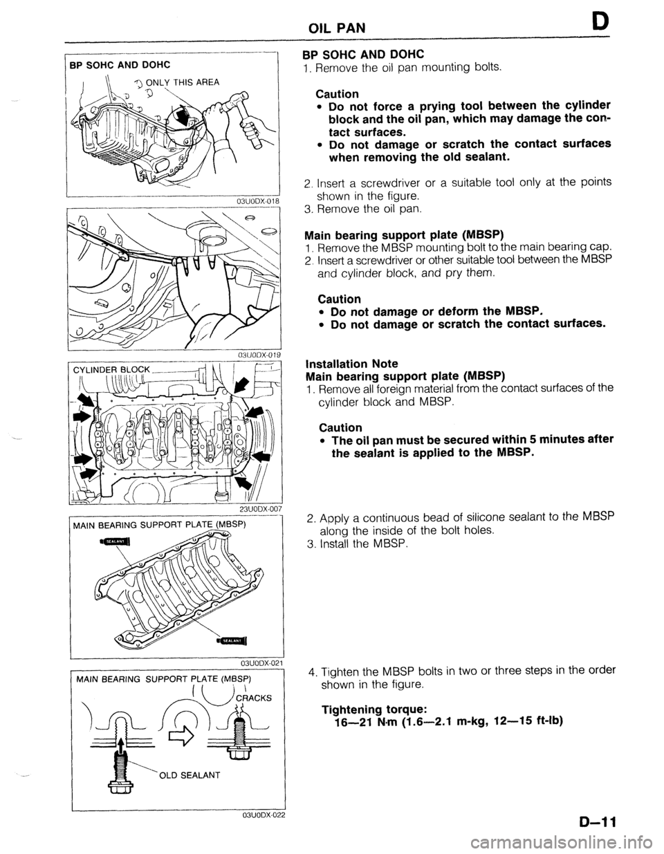
2. Insert a screwdriver or a suitable tool only at the points
shown in the figure.
3. Rernove the oil pan.
Main bearing support plate (MBSP)
1. Remove the MBSP mounting bolt to the main bearing cap.
2. Insert a screwdriver or other suitable tool between the MBSP
and cylinder block, and pry them.
Caution
l Do not damage or deform the MBSP.
l Do not damage or scratch the contact surfaces.
Installation Note
Main bearing support plate (MBSP)
1. Remove all foreign material from the contact surfaces of the
cylinder block and MBSP.
Caution
l The oil pan must be secured within 5 minutes after
the sealant is applied to the MBSP.
2. Apply a continuous bead of silicone sealant to the MBSP
along the inside of the bolt holes.
3. Install the MBSP.
4. Tighten the MBSP bolts in two or three steps in the order
shown in the figure.
Tightening torque:
16-21 N.m (1.6-2.1 m-kg, 12-15 ft-lb)
D-l 1
Page 267 of 1164
F
FUEL AND EMISSION
CONTROL SYSTEM
INDEX ...........................................
OUTLINE ...................................... ;: 2
SYSTEM DIAGRAM ...................... F-
:
VACUUM HOSE ROUTING
DIAGRAM .................................
WIRING DIAGRAM ....................... F- 6
- 7
ENGINE CONTROL UNIT (ATX) ...... F- 13
SPECIFICATIONS.. ....................... F- 15
COMPONENT DESCRIPTIONS.
...... F- 16
TROUBLESHOOTING GUIDE.. ......... F- 20
ENGINE CONTROL OPERATION
CHART
..................................... F- 20
RELATIONSHIP CHART.. .............. F- 24
USING THIS SECTION .................. F- 25
DIAGNOSTIC INDEX .................... F- 27
PRECAUTION ............................. F- 29
SYMPTOM TROUBLESHOOTING .... F- 30
ENGINE TUNE-UP
.......................... F- 76
PREPARATION ............................
F- 76
BASIC INSPECTION ..................... F- 78
ADJUSTMENT .............................
F- 79
SELF-DIAGNOSIS FUNCTION .......... F- 82
DESCRIPTION .............................
F- 82
PREPARATION
............................
F- 83
SERVISE CODE NUMBER.. ........... F- 83
SWITCH MONITOR FUNCTION ...... F-105
INTAKE AIR SYSTEM.. ................... F-109
COMPONENT PARTS.. ................. F-109
THROTTLE BODY ........................ F-l 12
DYNAMIC CHAMBER ................... F-l 12
INTAKE MANIFOLD ..................... F-l 13
ACCELERATOR PEDAL ................ F-l 14
ACCELERATOR CABLE ................ F-l 14
IDLE SPEED CONTROL (ISC)
SYSTEM ......................................
F-115
DESCRIPTION ............................. F-115
PREPARATION
............................ F-116
SYSTEM OPERATION.. ................. F-l 16
ISC VALVE ................................. F-116
AIR VALVE
................................. F-116
VARIABLE INERTIA CHARGING
SYSTEM (VICS) [DOHC] ................ F-l 17
DESCRIPTION ............................. F-117
SYSTEM OPERATION ................... F-l 18
SHUTTER VALVE ACTUATOR.. ...... F-l 18
SOLENOID VALVE (VICS). ............. F-118
VACUUM CHAMBER.. .................. F-119
FUELSYSTEM .............................. F-l 20
DESCRIPTION
............................. F-l 20
PRECAUTION ............................. F-121
SYSTEM OPERATION.. ................. F-121
FUEL TANK ................................
F-l 23
FUEL FILTER .............................. F-l 24 FUEL PUMP ............................... F-l 25
CIRCUIT OPENING RELAY.. .......... F-129
PRESSURE REGULATOR.. ............ F-129
INJECTOR .................................. F-l 31
PRESSURE REGULATOR
CONTROL SYSTEM.. .................... F-l 34
SOLENOID VALVE (PRESSURE
REGULATOR CONTROL). ............ F-l 35
EXHAUST SYSTEM ........................ F-l 36
COMPONENT PARTS.. ................. F-136
OUTLINE OF EMISSION
CONTROL SYSTEM.. .................... F-l 37
STRUCTURAL VIEW.. ................... F-l 37
POSITIVE CRANKCASE
VENTILATION (PCV) SYSTEM.. ..... F-138
DESCRIPTION .............................
F-l 38
PCV VALVE ................................ F-l 38
EVAPORATIVE EMISSION
CONTROL SYSTEM.. .................... F-l 39
DESCRIPTION ............................. F-l 39
SYSTEM OPERATION.. ................. F-140
SOLENOID VALVE
(PURGE CONTROL) ................... F-140
SEPARATOR ............................... F-l 40
CHECK VALVE (TWO-WAY) ........... F-140
CHECK-AND-CUT VALVE.. ............ F-141
CHARCOAL CANISTER.. ............... F-141
DECELERATION CONTROL
SYSTEM ...................................... F-l 42
DESCRIPTION ............................. F-l 42
DASHPOT .................................. F-142
FUEL CUT CONTROL SYSTEM ....... F-143
DESCRIPTION ............................. F-l 43
PREPARATION ............................ F-l 43
SYSTEM OPERATION.. ................. F-143
DECHOKE CONTROL SYSTEM.. ...... F-145
DESCRIPTION ............................. F-l 45
SYSTEM OPERATION ................... F-l 45
CONTROL SYSTEM ....................... F-l 47
PREPARATION ............................ F-147
STRUCTURAL VIEW.. ................... F-l 48
ENGINE CONTROL UNIT (ECU) ..... F-149
AIRFLOW METER (WITH INTAKE AIR
THERMOSENSOR) ..................... F-168
WATER THERMOSENSOR.. ........... F-168
THROTTLE SENSOR .................... F-l 69
OXYGEN SENSOR.. ..................... F-171
MAIN RELAY (FUEL INJ RELAY) .... F-172
CLUTCH SWITCH (MTX) ............... F-172
NEUTRAL SWITCH (MTX). ............. F-173
POWER STEERING PRESSURE
SWITCH .................................... F-173
WJOFX-001
Page 269 of 1164

INDEX F
1. Resonance duct
Inspection / Replacement.. ........ page F-l 09
2. Air cleaner element
Inspection ................................. page F- 79
Replacement.. ........................... page F-l 09
3. Airflow meter
(With intake air thermosensor)
Inspection
................................. page F-l 68
Replacement.. ........................... page F-l 09
4. Resonance chamber
Inspection I Replacement.. ........ page F-l 09
5. Throttle body
Inspection .................................
page F-l 12
Replacement.. ...........................
page F-l 09
6. Throttle sensor
inspection ................................. page F-l 69
Adjustment..
.............................. page F-l 69
Replacement.. ........................... page F-l 71
7. ISC valve
Inspection ................................. page F-l 16
Replacement..
........................... page F-l 09
8. Dashpot
Inspection ................................. page F-l 42
9. Dynamic chamber
Removal / Installation ................
page F-109
Inspection [DOHC] ................... page F-l 12
10. Air valve
Inspection
................................. page F-l 16
Removal / Installation ................ page F-109
11. Shutter valve actuator
Inspection ................................. page F-l 18
12. Vacuum chamber [DOHC]
Inspection ................................. page F-l 19
13. Intake manifold
Removal / Installation ................ page F-l 09
14. Injector
Inspection .................................
page F-l 31
Removal .................................... page F-131
Installation.. ............................... page F-l 33 15. Pressure regulator
Inspection ................................. page F-l 29
Replacement ............................. page F-l 30
16. Solenoid valve (Pressure regulator control)
[BP1
Inspection ................................. page F-l 35
17. Solenoid valve (VICS) [DOHC]
Inspection ................................. page F-l 18
18. Charcoal canister
Inspection ................................. page F-l 41
19. Solenoid valve (Purge control)
Inspection ................................. page F-l 40
20. Circuit opening relay
Inspection ................................. page F-l 29
Replacement ............................. page F-l 29
21. Engine control unit (ECU)
Removal / Installation ................ page F-l 49
Inspection ................................. page F-149
22. Clutch switch (MTX)
Inspection ................................. page F-l 72
Replacement.. ........................... page F-l 72
23. PCV valve
Inspection ................................. page F-l 38
24. Water thermosensor
Removal / Inspection /
Installation ............................... page F-l 68
25. Fuel filter (High-pressure side)
Replacement.. ........................... page F-l 24
26. Main relay (FUEL INJ relay)
Inspection ................................. page F-l 72
27. Neutral switch (MTX)
inspection ................................. page F-l 73
Replacement.. ........................... page F-l 73
28. Oxygen sensor
Inspection ................................. page F-l 71
Replacement ............................. page F-l 72
29. Power steering pressure switch
Inspection ................................. page F-l 73
Replacement.. ........................... page F-l 73
23UOFX-002
F-3
Page 279 of 1164

OUTLINE F
ENGINE CONTROL UNIT (ATX)
The engine control unit (ECU) is united with the EC-AT control unit for simplification of the system.
PREVIOUS
I
EC-AT CONTROL UNIT
OUTPUT DEVICES
ENGINE CONTROL
I I MALFUNCTION DISPLAY FUNCTION
I
L- ------ -------- ----__ __J
NEW ENGINE/EC-AT CONTROL UNIT
-----------m--e-
I
1
1
4
I I
OUTPUT
*
h
T I
NPUT SIGNALS I )c
I ENGINE CONTROL
‘I
FAIL-SAFE FUNCTION
NPUT SIGNALS I EC-AT CONTROL
I DEVICE!
OUTPUT DEVICE:
23UOFX-01
Signals input to the combined engine/EC-AT control unit are classified into engine and EC-AT control signals within the unit.
The operation of the engine control and EC-AT control are unchanged from the previous model.
F-l 3
Page 282 of 1164
F OUTLINE
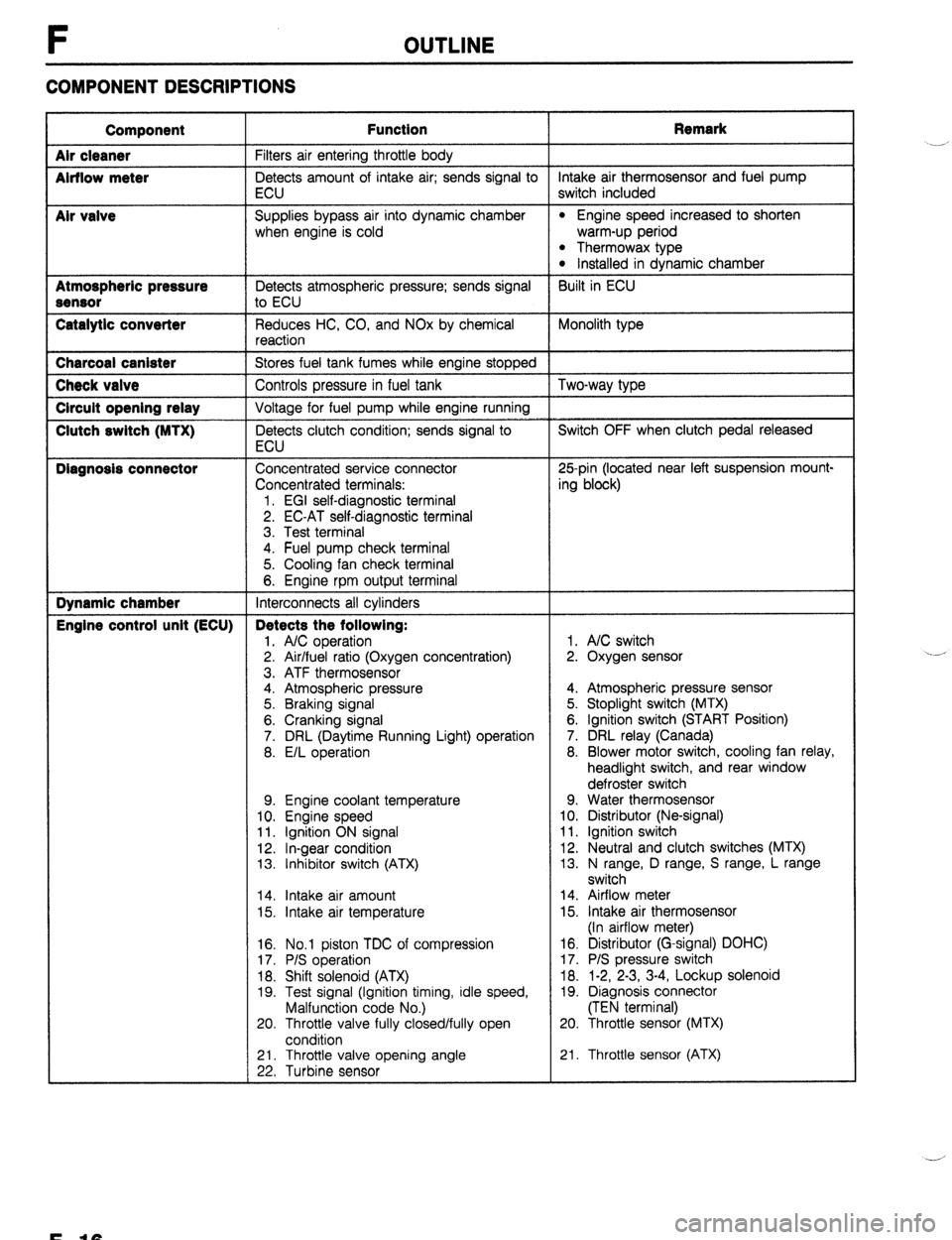
COMPONENT DESCRIPTIONS
Component
Air cleaner
Airflow meter
Mr valve
Atmospheric pressure
Sensor
Catalytic converter Function Remark
Filters air entering throttle body
Detects amount of intake air; sends signal to intake air thermosensor and fuel pump
ECU switch included
Supplies bypass air into dynamic chamber
l Engine speed increased to shorten
when engine is cold warm-up period
l Thermowax type l Installed in dynamic chamber
Detects atmospheric pressure; sends signal Built in ECU
to ECU
Reduces HC, CO, and NOx by chemical Monolith type
reaction Charcoal canister
Stores fuel tank fumes while engine stopped Check valve
Controls pressure in fuel tank Two-way type Circuit opening relay
Voltage for fuel pump while engine running Clutch switch (MTX)
Detects clutch condition; sends signal to Switch OFF when clutch pedal released
ECU Diagnosis connector
Concentrated service connector 25pin (located near left suspension mount-
Concentrated terminals: ing block)
1. EGI self-diagnostic terminal
2. EC-AT self-diagnostic terminal
3. Test terminal
4. Fuel pump check terminal
5. Cooling fan check terminal
6. Engine rpm output terminal Dynamic chamber
Interconnects all cylinders Engine control unit (ECU) Detects the following:
1. A/C operation 1. A/C switch
2. Air/fuel ratio (Oxygen concentration) 2. Oxygen sensor
3. ATF thermosensor
4. Atmospheric pressure 4. Atmospheric pressure sensor
5. Braking signal 5. Stoplight switch (MTX)
6. Cranking signal 6. Ignition switch (START Position)
7. DRL (Daytime Running Light) operation 7. DRL relay (Canada)
8. E/L operation 8. Blower motor switch, cooling fan relay,
headlight switch, and rear window
defroster switch
9. Engine coolant temperature 9. Water thermosensor
10. Engine speed 10. Distributor (Ne-signal)
11. Ignition ON signal 11. Ignition switch
12. In-gear condition 12. Neutral and clutch switches (MTX)
13. Inhibitor switch (ATX) 13. N range, D range, S range, L range
switch
14. Intake air amount 14. Airflow meter
15. Intake air temperature 15. Intake air thermosensor
(In airflow meter)
16. No.1 piston TDC of compression
17. P/S operation
18. Shift solenoid (ATX)
19. Test signal (Ignition timing, idle speed,
Malfunction code No.)
20. Throttle valve fully closed/fully open
condition 16. Distributor (G-signal) DOHC)
17. P/S pressure switch
18. 1-2, 2-3, 3-4, Lockup solenoid
19. Diagnosis connector
(TEN terminal)
20. Throttle sensor (MTX)
21. Throttle valve opening angle
22. Turbine sensor 21. Throttle sensor (ATX) .__r
F-10
Page 283 of 1164
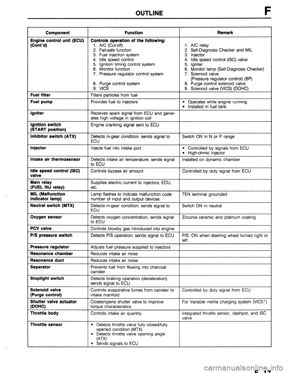
OUTLINE
Component Function Remark
Engine control unit (ECU) Controls operation of the following:
(Cont’d)
1. A/C (Cut-off) 1. A/C relay
2. Fail-safe function 2. Self-Diagnosis Checker and MIL
3. Fuel injection system 3. Injector
4. idle speed control 4. Idle speed control (ISC) valve
5. Ignition timing control system 5. Igniter
6. Monitor function 6. Monitor lamp (Self-Diagnosis Checker)
7. Pressure regulator control system 7. Solenoid valve
(Pressure regulator control) (BP)
8. Purge control system 8. Purge control solenoid valve
9. VICS 9. Solenoid valve (WCS) (DOHC) Fuel filter
Filters particles from fuel Fuel pump
Provides fuel to injectors l Operates while engine running l Installed in fuel tank Igniter
Receives spark signal from ECU and gener-
ates high voltage in ignition coil Ignition switch
Engine cranking signal sent to ECU (START position)
Inhibitor switch (ATX)
Detects in-gear condition; sends signal to Switch ON in N or P range
ECU Injector
Intake air thermosensor
Idle speed control (ISC)
valve
Main relay
(FUEL INJ relay)
MIL (Malfunction
indicator lamp)
Neutral switch (MTX)
Oxygen sensor
PCV valve
P/S pressure switch
Pressure regulator
Resonance chamber
Resonance duct
Separator
Stoplight switch
Solenoid valve
(Purge control)
Shutter valve actuator
(DOHC)
Throttle body
Throttle sensor
Injects fuel into intake port l Controlled by signals from ECU
l High-ohmic injector
Detects intake air temperature; sends signal Installed on dynamic chamber
to ECU
Controls bypass air amount Controlled by duty signal from ECU
Supplies electric current to injectors, ECU,
etc.
Lamp flashes to indicate malfunction code
number of input and output devices
Detects in-gear condition; sends signal to
ECU
Detects oxygen concentration; sends signal
to ECU
Controls blowby gas introduced into engine
Detects P/S operation; sends signal to ECU
Adjusts fuel pressure supplied to injectors
Reduces intake air noise
Reduces intake air noise
Prevents fuel from flowing into charcoal
canister
Detects braking operation (deceleration),
sends signal to ECU
Controls evaporative fumes from canister to
intake manifold
Closes/opens shutter valve to improve
torque characteristics
Controls intake air quantity
l Detects throttle valve fully closed/fully
opened condition (MTX) TEN terminal grounded
Switch ON in neutral
Zirconia ceramic and platinum coating
P/S: ON when steering wheel turned right or
left
Controlled by duty signal from ECU
For Variable inertia charging system (VICS*)
Integrated throttle sensor, dashpot, and ISC
valve
l Detects throttle valve opening angle
(A-W
l Sends signals to ECU
F-l 7