radiator MAZDA PROTEGE 1992 Owner's Manual
[x] Cancel search | Manufacturer: MAZDA, Model Year: 1992, Model line: PROTEGE, Model: MAZDA PROTEGE 1992Pages: 1164, PDF Size: 81.9 MB
Page 258 of 1164

E THERMOSTAT
Installation Note JIGGLE PIN Thermostat
6 8 8
1. Install the thermostat into the cylinder head with the jiggle
pin at the top. ..__
Thermostat gasket
1. Install a new gasket with the seal print side facing the cylin-
der head.
03UOEX-014
Steps After Installation
1. Fill the radiator with the specified amount and type of engine coolant. (Refer to page E-6.)
2. Connect the negative battery cable,
3. Start the engine and check for leaks.
03UOEX-015
.-
E-IO
Page 260 of 1164

BP DOHC
L 7.8-11 N-m (60-110 cm-kg, 69-95 in-lb)
E WATER PUMP
157-167
I
(W-17, 116-123) I
I
/
I
I
I
---N-w------
---------------
----_---_
-I
N.m (m-kg, ft-lb) 1
^^, *--., ^^^
1. Timing belt
Service . . . . . . . . . . . . . . . . . . . . . . . . . . . . . . . . . . . . . . . . Section 5. Water pump assembly
B2
2. Water inlet pipe and gasket Inspect for cracks, damaged mounting
3. Water bypass pipe and O-ring surface, bearing condition, and leakage
4. Oil dip stick pipe bracket 6. Water pump gasket
Steps After Installation
1. Fill the radiator with the specified amount and type of engine coolant. (Refer to page E-6.)
2. Connect the negative battery cable,
3. Start the engine and check for leaks.
03UOEX-018
E-12
Page 261 of 1164

ELECTRIC COOLING FAN SYSTEM E
ELECTRIC COOLING FAN SYSTEM
SYSTEM CIRCUIT
I
SINGLE-SPEED TYPE
WITH A/C
r __________ -------- ------..---- i
I
I
I -
I
I
r,
, II
I 1
P ’
iI
:”
IGZ
b CONNECTOR
WATER
THERMOSWITCH
ABOVE 97% (207OF): ON WO-SPEED TYPE
WITH AK
r--------
l
I
I
I
I
I
I I
I
I
I
L-
No.2
FAN
RELAY
ADDITIONAL
FAN
MOTOR - -_-_---
A-- 1- A/C SWITCH
_________ - -.--- -- _ .- .- - LDIAGNOSIS
CONNECTOR
WATER
THERMOSWITCH
ELAY ABOVE 97% (207“F): ON
RADIATOR SWITCH
ABOVE 105-Z (221°F): ON
03UOEX-019
E-13
Page 262 of 1164

E ELECTRIC COOLING FAN SYSTEM, FAN MOTOR
03UOEX-02
I
1
I
‘4
.
2
.:
)
SYSTEM INSPECTION
1. Jump across the fan test (TFA) terminal and the ground
(GND) terminal of the diagnosis connector.
2. Turn the ignition switch ON and verify that the fan operates.
If the fan does not operate, inspect the cooling fan system
components and wire harness. -.-
3. Remove the radiator cap and place a thermometer in the
radiator filler neck.
4. Start the engine.
5. Verify that the fan operates when the coolant temperature
reaches approx. 97OC (207OF).
If it does, check the water thermoswitch.
(Refer to page E-16.)
FAN MOTOR
INSPECTION
Single-Speed Type
1. Check that the battery is fully charged.
2. Disconnect the fan motor connector.
3. Connect the battery and an ammeter to the fan motor con-
nectar.
4. Verify that current is as specified.
Current (A)
B6 SOHC
BP SOHC
BP DOHC MTX ATX
6.6 f 1 6.6 f 1
6.6 f 1 -
6.6 f 1 -
5. If current is not within specification and/or the fan does not
turn smoothly, replace the fan motor.
Two-Speed Type
1. Check that the battery is fully charged.
2. Disconnect the fan motor connector.
3. Connect the battery and an ammeter to the fan motor con-
nectors for low-speed inspection. 4. Verify that the fan motor operates smoothly at the standard
current.
Current (A): 8.8 + 10% MAX
I
03UOEX-022
E-14
Page 263 of 1164

FAN MOTOR E
I-
i.- 5. Connect the battery, an ammeter, and switch to the fan mo-
tor connectors for high-speed inspection.
6. Verify that the fan motor operates smoothly at the standard
current or less with the switch ON.
Current (A): 13.3 + 10% MAX
7. If the fan motor is faulty, replace it.
---“-. --
REPLACEMENT
Caution
l Position the hose clamp in the original location on the hose, and squeeze the clamp lightly
with large pliers to ensure a good fit.
1. Disconnect the negative battery cable.
2. Drain the engine coolant.
3. Remove in the order shown in the figure.
4. Install in the reverse order of removal.
7.8-11 N.m
7.8-11 N.m
(80-110 cm-kg,
1. Resonance chamber
4. Radiator cowling
2. Cooling fan connector
5.
Cooling fan
3. Radiator hose upper
6. Fan motor
E-l 5
Page 265 of 1164

RADIATOR THERMOSWITCH E
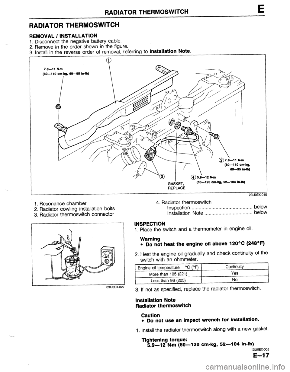
RADIATOR THERMOSWITCH
REMOVAL / INSTALLATION
1. Disconnect the negative battery cable.
2. Remove in the order shown in the figure.
3. Install in the reverse order of removal. referrina to
Installation Note.
(80-110 cm-kg,
69-95 in-lb)
GAdKET,
REPLACE (60-120 cm-kg, 52-104 In-lb)
1. Resonance chamber
2. Radiator cowling installation bolts
3. Radiator thermoswitch connector 4. Radiator thermoswitch
Inspection . . . . . . . . . . . . . . . ..*...,..,..................* below
Installation Note ..,.,........,.......,........,... below
1. Place the switch and a thermometer in engine oil.
03UOEX-02
INSPECTION
Warning
l Do not heat the engine oil above 120°C (248OF)
2. Heat the engine oil gradually and check continuity of the
switch with an ohmmeter.
Engine oil temperature OC (OF) Continuity
More than 105 (221)
Yes
Less than 96 (205) No
3. If not as specified, replace the radiator thermoswitch.
lnstallatlon Note
Radiator thermoswitch
Caution
l Do not use an impact wrench for installation.
1. Install the radiator thermoswitch along with a new gasket.
Tightening torque:
5.9-12 N#m (60-l 20 cm-kg, 52-104 in-lb)
13UOEX-005
E-17
Page 338 of 1164

F TROUBLESHOOTING GUIDE
STEP INSPECTION ACTION
5 Check for correct fuel line pressure at idle Yes Check if fuel line pressure decreases
w page F-129 when accelerating quickly
Fuel line pressure: + If it decreases, check for clogging
265-314 kPa (2.7-3.2 kg/cm’, 36-46 psi) between fuel pump and pressure
(Vacuum hose to pressure regulator dis- regulator
connected) * If not decrease, go to next step
INSTALL CLAMPS No Low pressure
Check fuel line pressure while pinching
fuel return hose
c3 If fuel line pressure quickly in-
creases, check pressure regulator w page F-129
c3 If fuel line pressure gradually in-
creases, check for clogging be-
tween fuel pump and pressure
regulator
If not clogged, check fuel pump
maximum pressure w page F-126
6 Check if cooling system is OK Yes Go to next step
w page E-13
No Repair or replace
l Thermostat w page E-9
l Electric cooling fan w page E-16 l Radiator w page E-6
7 Try known good ECU and check if condition Yes Replace ECU CT page F-149
improves
CT= page F-149 No
Change fuel to another brand or use
higher octane fuel
23lJOFX.0: .-._ ,
F-72
Page 344 of 1164

F ENGINE TUNE-UP
ENGINE TUNE-UP
PREPARATlON
SST
I
I I
49 BO19 9AO
System Selector For
inspection of igni-
tion timing and
idle speed
hA ‘I
03UOFX-04
03UOFX-04
03UOFX-04
NG POINT
03UOFX-04 03UOFX-045
BASIC INSPECTION
Engine Oil
1. Remove the engine oil level gauge and check the engine
oil level and oil condition.
2. Add or change the oil as necessary.
Coolant
Warning
l Never remove the radiator cap while the engine is
hot.
l Wrap a thick cloth around the cap before carefully
removing it.
1. Remove the coolant level gauge from the coolant reservoir.
2. Check that the coolant level is between the L and F marks
of the gauge.
3. Add coolant if necessary.
Battery
1. Check for corrosion on the terminals and for loose cable
connections. If necessary, clean the clamps and tighten
them firmly.
2. Check that the electrolyte level is between the UPPER LEV-
EL and LOWER LEVEL marks.
3. Add distilled water if necessary.
4. Check the specific gravity with a hydrometer.
Gravity: 1.27-l .29 (at 20% [68OF] )
Page 379 of 1164

INTAKE AIR SYSTEM F
I 23UOFX-096
INTAKE MANIFOLD
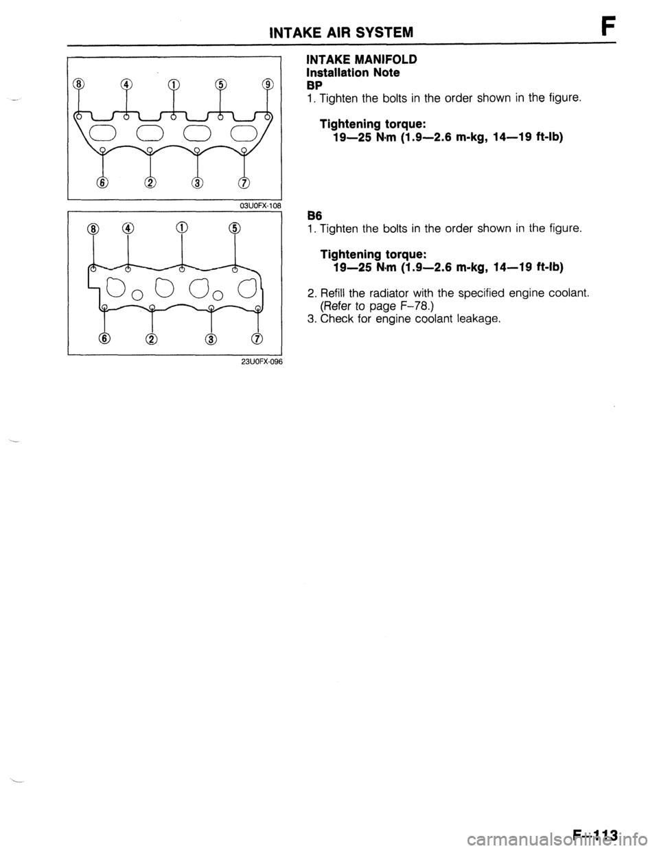
Installation Note
BP
1, Tighten the bolts in the order shown in the figure.
Tightening torque:
19-25 N-m (1.9-2.6 m-kg, 14-19 ft-lb)
B6
1. Tighten the bolts in the order shown in the figure.
Tightening torque:
19-25 N-m (1.9-2.6 m-kg, 14-19 ft-lb)
2. Refill the radiator with the specified engine coolant.
(Refer to page F-78.)
3. Check for engine coolant leakage.
F-113
Page 710 of 1164

R OUTLINE
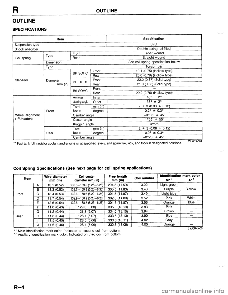
OUTLINE
SPECIFICATIONS
Suspension type Item Specification Strut
Shock absorber Double-acting, oil-filled
Coil spring
Stabilizer Type Front Taper wound
Rear Straight wound
Dimension See coil spring specification below
Type Torsion bar
BP SOHC Front 19.1 (0.75) (Hollow type)
Rear 20.0 (0.79) (Hollow type)
Diameter 22.0 (0.87) (Solid type)
mm (in) BP DOHC ;eTrt
21 .O (0.83) (Solid type)
P ,
-
66 SOHC rronr
Rear 20.0 (0.79) (Hollow type)
Maximum Inner 400 f 20
steering angle
Outer 330 f 20
Total mm (in) 2 f 3 (0.08 f 0.12)
Front toe-in
degree 0.2O f 0.3O
Wheel alignment
(*‘Unladen) Camber angle -0005’ f 45’
Caster angle 1055 * 55’
Kingpin angle 12O25’
Total mm (in) 2 f 3 (0.08 * 0.12)
Rear toe-in
degree 0.2O f 0.3O
Camber angle -0°20’ f 45’
*’ Fuel tank full; radiator coolant and engine oil at specified levels; and spare tire, jack, and tools in designated positions.
23UORX.004
Coil Spring Specifications (See next page for coil spring applications)
I Item Wire diameter Coil center Free lel.=-. .
mm iin1 rliamotor mm [in mm (in 1 coil numbs
Front
nath
1 _ . . *St Identification mark color +l
., . . . . I...,
-*.....-.“, * . . . . . ,..-, -....- I--‘, M iA*=
A 13.1 (0.52) 133.5-159.5 (5.26-6.28)
294.5 (11.59) 3.22 Light green
B 13.3 (0.52) 133.7-159.9 (5.26-6.30) 300.5 (11.83)
3.43 Purple Yellow
C 13.4 (0.53)
132.6-158.6 (5.22-6.24) 301.5 (11.87) 3.49
Light blue
D 13.7 (0.54)
132.9-158.9 (5.23-6.26) 302.0 (11.89) 3.52
Pink White
I F I 12f3 Kl5Al I 1.17 A-l!% 8 f!i PR-Fi 751
I RrIl .5 II 1 6x71 I 3.56 Orange
Blue
3 83 Pink -
Brown - .“._ \“.- .,
. “W.., ~ - -. - \-. -- -. - -, -- .-
\’ .‘-‘I t
F 11 .o (0.43) 129.0 (5.08)
335.0 (13.19) -.--
G 11.2 (0.44) 128.8 (5.07)
334.0 (13.15) 3.94
Rnnr l-4
1 I ? 07 AA 1387 /5n7
.?m !i 113 1% 3 an Blue - I I I I .” \v.-7, I&V., \V.“., ---.., \.-. .-, I 11.5 (0.45) 128.5 (5.06)
333.0 (13.11) i:oi Gray
-
J 11.6 (0.46) 128.4 (5.06)
332.5 (13.09) 4.00 Orange
-
l ’ Main identification mark color: Indicated on second coil from bottom.
*’ Auxiliary identification mark color: Indicated on third coil from bottom. 23UORX-005
R-4