check oil MAZDA PROTEGE 1992 Workshop Manual
[x] Cancel search | Manufacturer: MAZDA, Model Year: 1992, Model line: PROTEGE, Model: MAZDA PROTEGE 1992Pages: 1164, PDF Size: 81.9 MB
Page 20 of 1164
PRE-DELIVERY INSPECTION
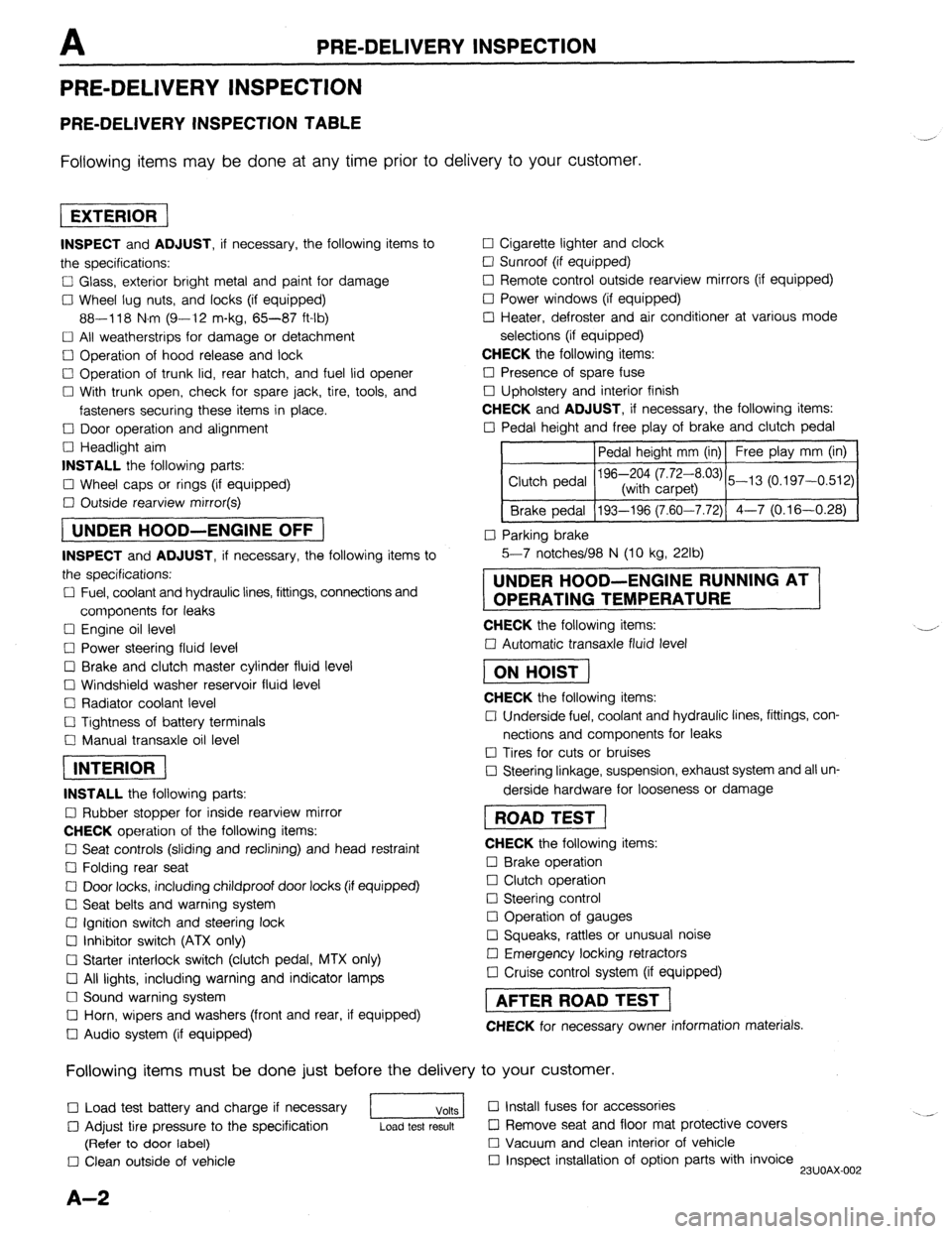
PRE-DELIVERY INSPECTION
PRE-DELIVERY INSPECTION TABLE
Following items may be done at any time prior to delivery to your customer.
INSPECT and ADJUST, if necessary, the following items to
the specifications:
0 Glass, exterior bright metal and paint for damage
Cl Wheel lug nuts, and locks (if equipped)
88-118 N.m (9-12 m-kg, 65-87 ft-lb)
q All weatherstrips for damage or detachment
0 Operation of hood release and lock
0 Operation of trunk lid, rear hatch, and fuel lid opener
Cl With trunk open, check for spare jack, tire, tools, and
fasteners securing these items in place.
Cl Door operation and alignment
Cl Headlight aim
INSTALL the following parts:
Cl Wheel caps or rings (if equipped)
q Outside rearview mirror(s)
1 UNDER HOOD-ENGINE OFF )
INSPECT and ADJUST, if necessary, the following items to
the specifications:
0 Fuel, coolant and hydraulic lines, fittings, connections and
components for leaks
Cl Engine oil level
0 Power steering fluid level
0 Brake and clutch master cylinder fluid level
El Windshield washer reservoir fluid level
Cl Radiator coolant level
Cl Tightness of battery terminals
Cl Manual transaxle oil level
riizmiq
INSTALL the following parts:
Cl Rubber stopper for inside rearview mirror
CHECK operation of the following items:
0 Seat controls (sliding and reclining) and head restraint
Cl Folding rear seat
0 Door locks, including childproof door locks (if equipped)
Seat belts and warning system
Cl Ignition switch and steering lock
0 Inhibitor switch (ATX only)
U Starter interlock switch (clutch pedal, MTX only)
Cl All lights, including warning and indicator lamps
Cl Sound warning system
Cl Horn, wipers and washers (front and rear, if equipped)
0 Audio system (if equipped) 0 Cigarette lighter and clock
0 Sunroof (if equipped)
II Remote control outside rearview mirrors (if equipped)
Cl Power windows (if equipped)
q Heater, defroster and air conditioner at various mode
selections (if equipped)
CHECK the following items:
Cl Presence of spare fuse
0 Upholstery and interior finish
CHECK and ADJUST, if necessary, the following items:
0 Pedal height and free play of brake and clutch pedal
Pedal height mm (in) Free play mm (in)
0 Parking brake
5-7 notches/98 N (10 kg, 22lb)
UNDER HOOD-ENGINE RUNNING AT
OPERATING TEMPERATURE
CHECK the following items:
q Automatic transaxle fluid level
[I
CHECK the following items:
Cl Underside fuel, coolant and hydraulic lines, fittings, con-
nections and components for leaks
0 Tires for cuts or bruises
0 Steering linkage, suspension, exhaust system and all un-
derside hardware for looseness or damage
[I
CHECK the following items:
0 Brake operation
0 Clutch operation
Cl Steering control
Cl Operation of gauges
q Squeaks, rattles or unusual noise
Cl Emergency locking retractors
0 Cruise control system (if equipped)
1 AFTER ROAD TEST (
CHECK for necessary owner information materials.
Following items must be done just before the delivery to your customer.
q Load test battery and charge if necessary
1 Volts 1 0 Install fuses for accessories
i.. _
0 Adjust tire pressure to the specification
Load test result cl Remove seat and floor mat protective covers
(Refer to door label) 0 Vacuum and clean interior of vehicle
0 Clean outside of vehicle q Inspect installation of option parts with invoice
23UOAX-002
A-2
Page 35 of 1164
ENGINE TUNE-UP PROCEDURE Bl
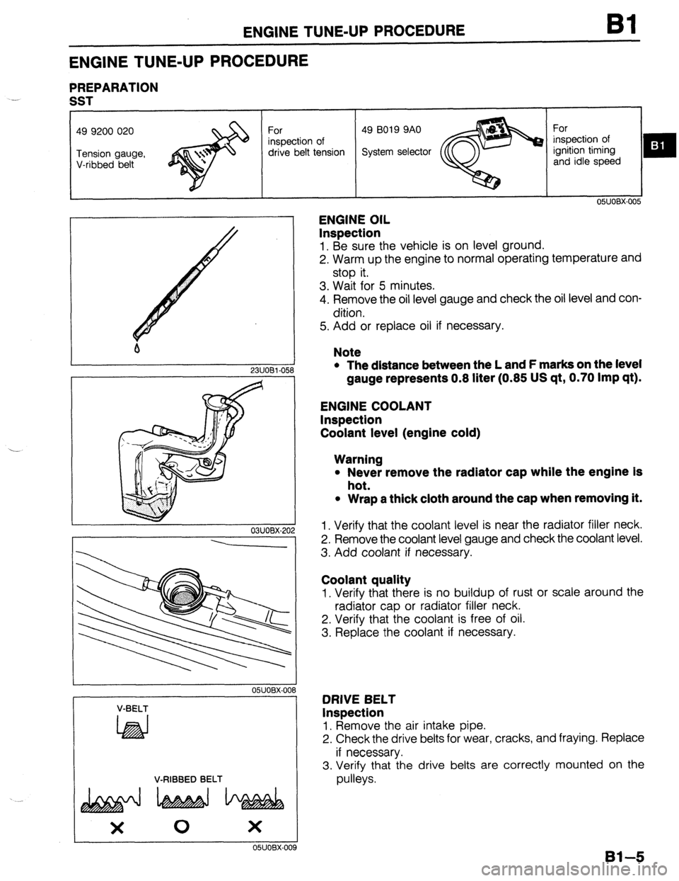
ENGINE TUNE-UP PROCEDURE
PREPARATION
-.
SST
drive belt tension
m :
I 1 2311081-058
- 03UOBX-20
---
OSUOBX-OC
V-BELT
LhEd
V-RIBBED BELT
OSJOBX-00
ENGINE OIL
Inspection
1. Be sure the vehicle is on level ground.
2. Warm up the engine to normal operating temperature and
stop it.
3. Wait for 5 minutes.
4. Remove the oil level gauge and check the oil level and con-
dition.
5. Add or replace oil if necessary.
Note
l The distance between the L and F marks on the level
gauge represents 0.8 liter (0.85 US qt, 0.70 Imp qt).
ENGINE COOLANT
Inspection
Coolant level (engine cold)
Warning
l Never remove the radiator cap while the engine is
hot.
l Wrap a thick cloth around the cap when removing it.
1. Verify that the coolant level is near the radiator filler neck.
2. Remove the coolant level gauge and check the coolant level.
3. Add coolant if necessary.
Coolant quality
1. Verify that there is no buildup of rust or scale around the
radiator cap or radiator filler neck.
2. Verify that the coolant is free of oil.
3. Replace the coolant if necessary.
DRIVE BELT
Inspection
1, Remove the air intake pipe.
2. Check the drive belts for wear, cracks, and fraying. Replace
if necessary.
3. Verify that the drive belts are correctly mounted on the
pulleys.
Bl--5
Page 37 of 1164
ENGINE TUNE-UP PROCEDURE Bl
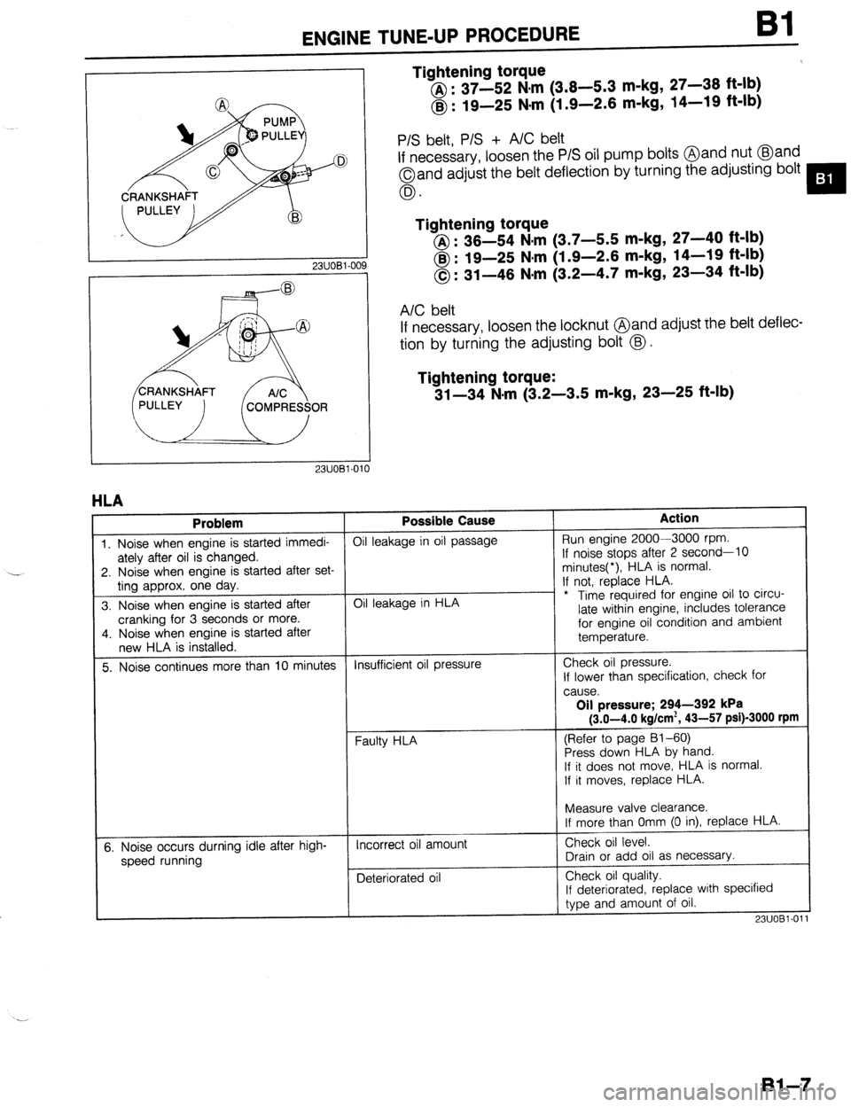
Tightening torque
@ : 37-52 N,m (3.8-5.3 m-kg, 27-38 ft-lb)
@ : 19-25 Nsm (1.9-2.6 m-kg, 14-19 ft-lb)
23UOBl-OC
P/S belt, P/S + A/C belt
If necessary, loosen the P/S oil pump bolts @and nut @and
Oand adjust the belt deflection by turning the adjusting bolt
0.
Tightening torque
@I : 36-54 N.m (3.7-5.5 m-kg, 27-40 ft-lb)
@ : 19-25 N#m (1.9-2.6 m-kg, 14-19 ft-lb)
0: 31-46 N-m (3.2-4.7 m-kg, 23-34 ft-lb)
A/C belt
If necessary, loosen the locknut @and adjust rhe belt deflec-
tion by turning the adjusting bolt @.
Tightening torque:
31-34 N-m (3.2-3.5 m-kg, 23-25 ft-lb)
1
HLA
Problem Possible Cause Action
1. Noise when engine is started immedi- Oil leakage in oil passage Run engine 2000-3000 rpm.
ately after oil is changed. If noise stops after 2 second-10
2. Noise when engine is started after set- minutes(*), HLA is normal.
ting approx. one day. If not, replace HLA.
3. Noise when engine is started after Oil leakage in HLA - * Time required for engine oil to circu-
cranking for 3 seconds or more. late within engine, includes tolerance
4. Noise when engine is started after for engine oil condition and ambient
new HLA is installed. temperature.
5. Noise continues more than 10 minutes Insufficient oil pressure Check oil pressure.
If lower than specification, check for
cause.
Oil pressure; 294-392 kPa
(3.0-4.0 kg/cm*, 43-57 psi)-3000 rpm
(Refer to page 81-60)
Press down HLA by hand.
If it does not move,. HLA is normal.
If it moves, replace HLA.
t
I
Measure valve clearance.
If more than Omm (0 in), replace HLA.
5. Noise occurs durning idle after high-
speed running Incorrect oil amount
Deteriorated oil Check oil level.
Drain or add oil as necessary.
Check oil quality.
If deteriorated, replace with specified
type and amount of oil.
23UOBl-01
Bl-7
Page 40 of 1164
Bl COMPRESSION
COMPRESSION
If the engine exhibits low power, poor fuel economy, or poor idle, check the following:
1. Ignition system (Refer to Section G.)
2. Compression
3. Fuel system (Refer to Section F.)
23UOBl-01
23UOBl-06
23UOBl-014 23UOBl-012
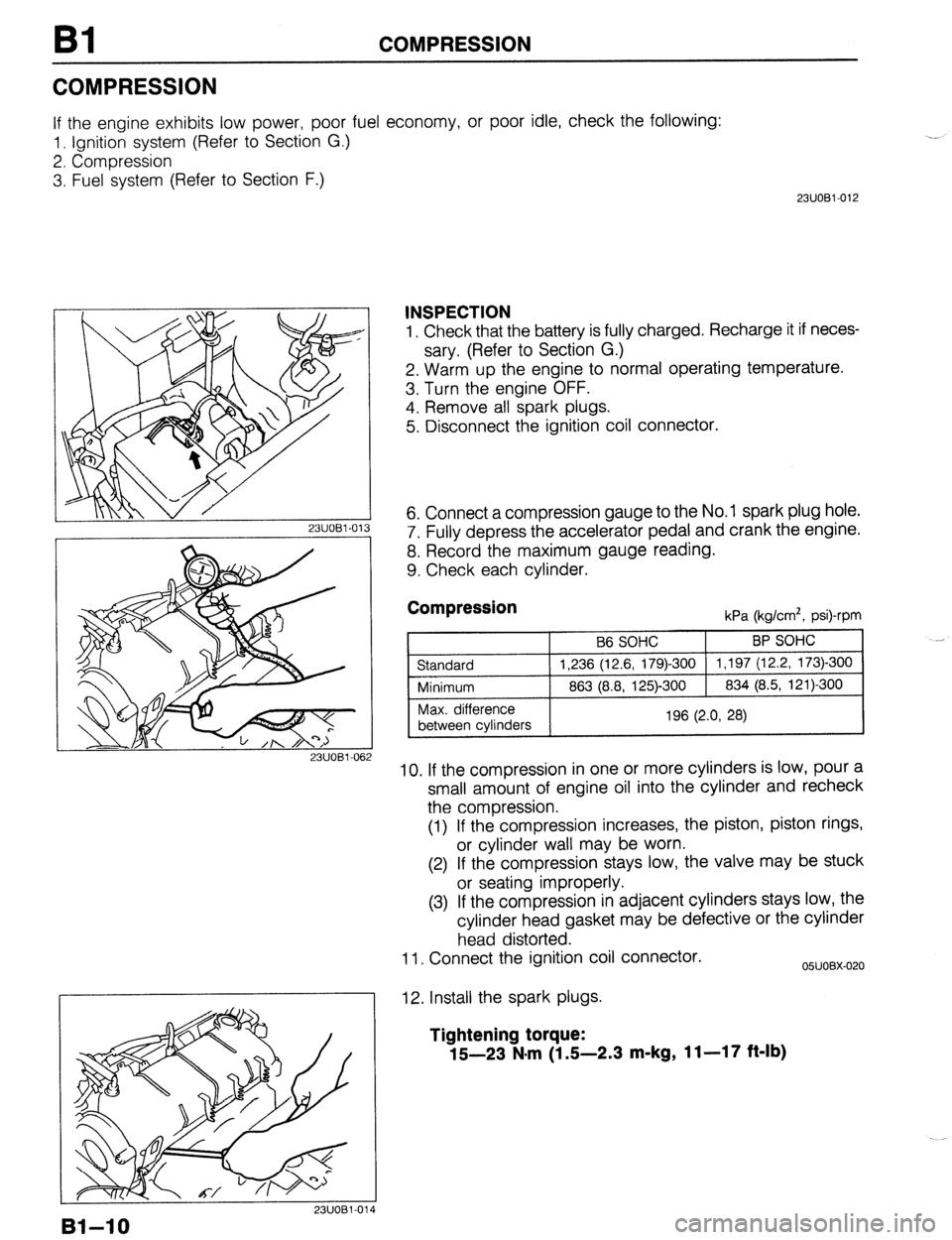
INSPECTION
1. Check that the battery is fully charged. Recharge it if neces-
sary. (Refer to Section G.)
2. Warm up the engine to normal operating temperature.
3. Turn the engine OFF.
4. Remove all spark plugs.
5. Disconnect the ignition coil connector.
6. Connect a compression gauge to the No. 1 spark plug hole.
7. Fully depress the accelerator pedal and crank the engine.
8. Record the maximum gauge reading.
9. Check each cylinder.
Compression kPa (kg/cm*, psi)-rpm
10. If the compression in one or more cylinders is low, pour a
small amount of engine oil into the cylinder and recheck
the compression.
(1) If the compression increases, the piston, piston rings,
or cylinder wall may be worn.
(2) If the compression stays low, the valve may be stuck
or seating improperly.
(3) If the compression in adjacent cylinders stays low, the
cylinder head gasket may be defective or the cylinder
head distorted.
11. Connect the ignition coil connector.
12. Install the spark plugs.
05UOBX-020
Tightening torque:
15-23 N*m (1 S-2.3 m-kg, 11-17 ft-lb)
Bl-10
Page 49 of 1164
.
ON-VEHICLE MAINTENANCE
Installation note
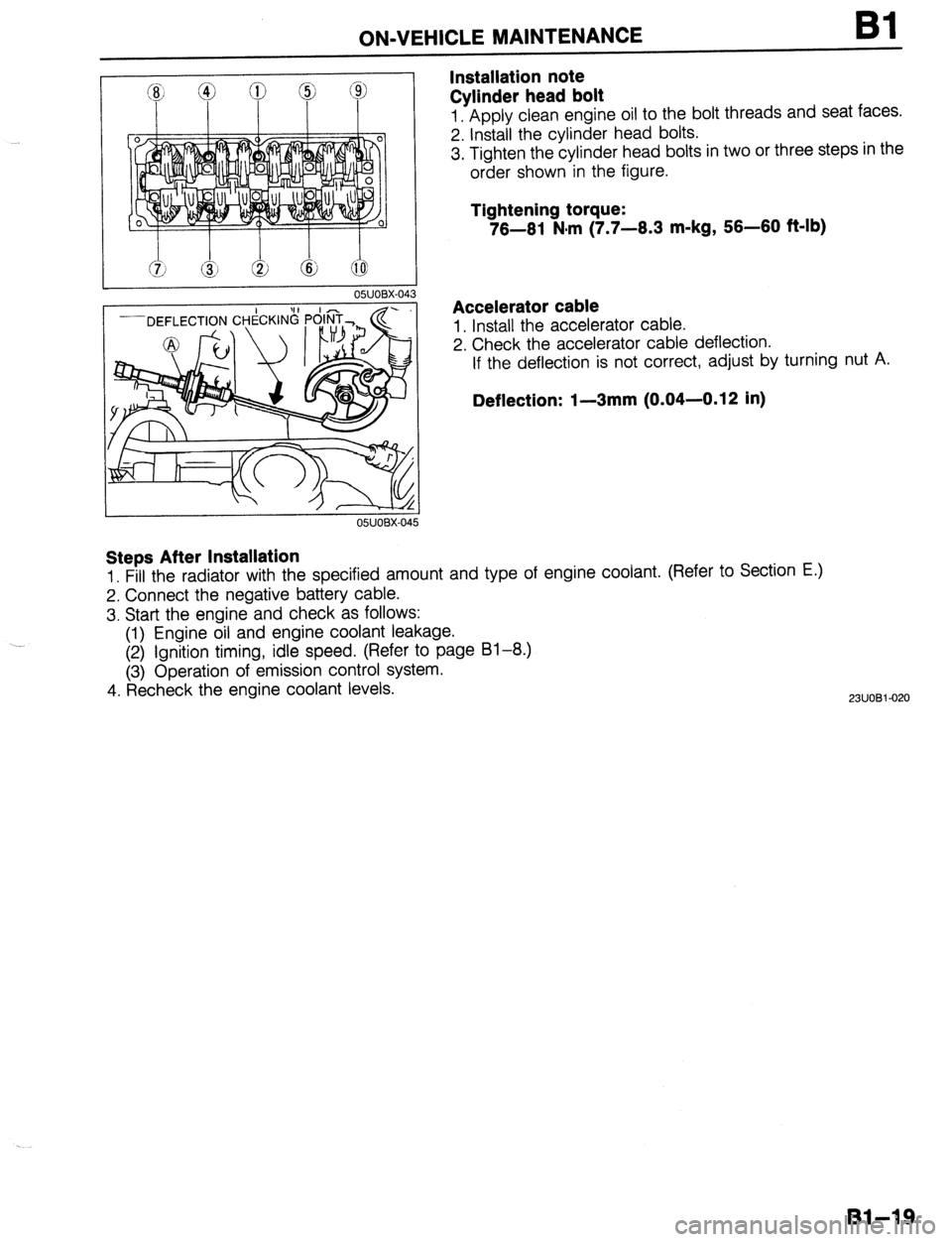
Cylinder head bolt Bl
1. Apply clean engine oil to the bolt threads and seat faces.
2. Install the cylinder head bolts.
3. Tighten the cylinder head bolts in two or three steps in the
order shown in the figure.
Tightening torque:
76-61 N#m (7.7-6.3 m-kg, 56-60 f&lb)
Accelerator cable
1. Install the accelerator cable.
2. Check the accelerator cable deflection.
If the deflection is not correct, adjust by turning nut A.
Deflection: I-3mm (0.04-0.12 in)
Steps After Installation
1. Fill the radiator with the specified amount and type of engine coolant. (Refer to Section E.)
2. Connect the negative battery cable.
3. Start the engine and check as follows:
(1) Engine oil and engine coolant leakage.
(2) Ignition timing, idle speed. (Refer to page 81-8.)
(3) Operation of emission control system.
4. Recheck the engine coolant levels.
2311081-020
Bl-19
Page 54 of 1164
Bl ON-VEHICLE MAINTENANCE
01 EOBX-056
23UOBi -0:
Steps After Installation
1. Lower the vehicle.
2. Connect the negative battery cable.
3. Start the engine and check the ignition timing.
(Refer to page 61-8)
Installation Note
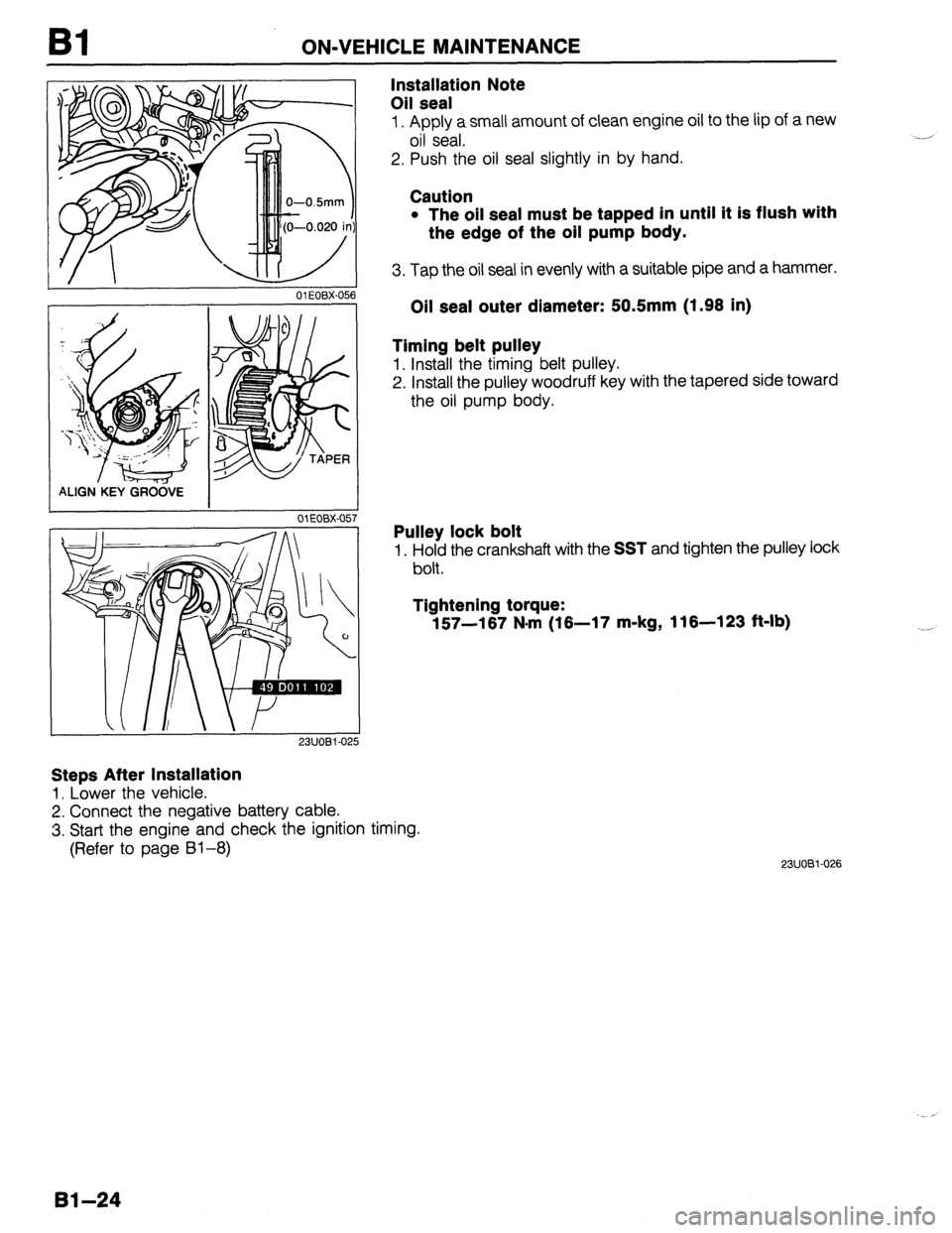
Oil seal
1. Apply a small amount of clean engine oil to the lip of a new
oil seal.
2. Push the oil seal slightly in by hand.
Caution
l The oil seal must be tapped in until it is flush with
the edge of the oil pump body.
3. Tap the oil seal in evenly with a suitable pipe and a hammer.
Oil seal outer diameter: 50.5mm (1.98 in)
Timing belt pulley
1. Install the timing belt pulley.
2. Install the pulley woodruff key with the tapered side toward
the oil pump body.
Pulley lock bolt
1. Hold the crankshaft with the SST and tighten the pulley lock
bolt.
Tightening torque:
157-167 N*rn (16-17 m-kg, 116-123 ft-lb)
23UOBi-026
Bl-24
Page 81 of 1164
DISASSEMBLY Bl
23UOBl-03
05UOBX-1’ 9
23UOBl-040
03UOBl-08 5
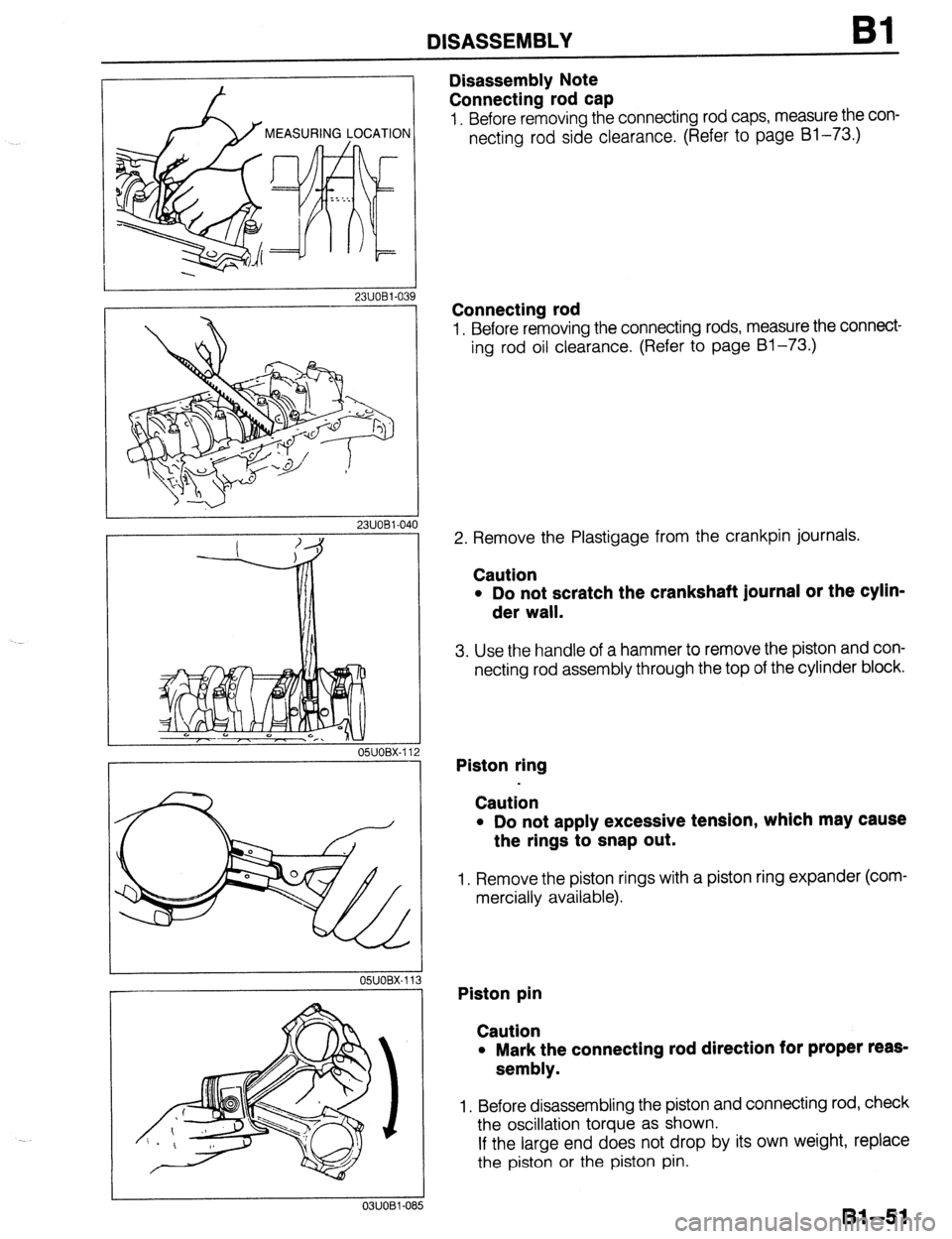
Disassembly Note
Connecting rod cap
1. Before removing the connecting rod caps, measure the con-
necting rod side clearance. (Refer to page Bl-73.)
Connecting rod
1. Before removing the connecting rods, measure the connect-
ing rod oil clearance. (Refer to page Bl-73.)
2. Remove the Plastigage from the crankpin journals.
Caution
l Do not scratch the crankshaft journal or the cylin-
der wall.
3. Use the handle of a hammer to remove the piston and con-
necting rod assembly through the top of the cylinder block.
Piston ring
Caution
l Do not apply excessive tension, which may cause
the rings to snap out.
1. Remove the piston rings with a piston ring expander (com-
mercially available).
Piston pin
Caution
l Mark the connecting rod direction for proper reas-
sembly.
1. Before disassembling the piston and connecting rod, check
the oscillation torque as shown.
If the large end does not drop by its own weight, replace
the piston or the piston pin.
81-51
Page 84 of 1164
Bl INSPECTION / REPAIR
INSPECTION / REPAIR
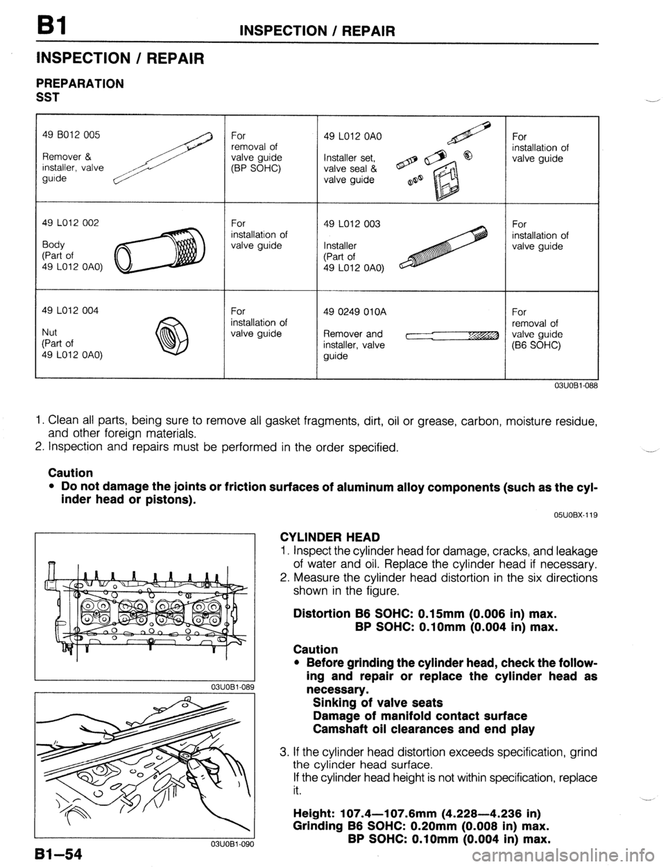
PREPARATION
SST
49 LO12 OAO)
Remover and
03UOBi-08
1. Clean all parts, being sure to remove all gasket fragments, dirt, oil or grease, carbon, moisture residue,
and other foreign materials.
2. Inspection and repairs must be performed in the order specified. .__a
Caution
l Do not damage the joints or friction surfaces of aluminum alloy components (such as the cyl-
inder head or pistons).
81-54
03UOBl-090 05UOBX-119
CYLINDER HEAD
1. Inspect the cylinder head for damage, cracks, and leakage
of water and oil. Replace the cylinder head if necessary.
2. Measure the cylinder head distortion in the six directions
shown in the figure.
Distortion B6 SOHC: 0.15mm (0.006 in) max.
BP SOHC: O.lOmm (0.004 in) max.
Caution
l Before grinding the cylinder head, check the follow-
ing and repair or replace the cylinder head as
necessary.
Sinking of valve seats
Damage of manifold contact surface
Camshaft oil clearances and end play
3. If the cylinder head distortion exceeds specification, grind
the cylinder head surface.
If the cylinder head height is not within specification, replace
it.
Height: 107.4-l 07.6mm (4.228-4.236 in)
Grinding B6 SOHC: 0.20mm (0.008 in) max.
BP SOHC: O.lOmm (0.004 in) max.
Page 90 of 1164
Bl INSPECTION / REPAIR
a3
03UOBl.109
03UOBl-11t
03UOBl-111 i
3
03UOBl-112
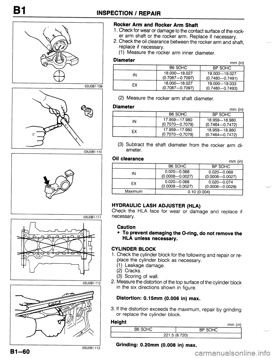
Rocker Arm and Rocker Arm Shaft
1. Check for wear or damage to the contact surface of the rock-
er arm shaft or the rocker arm. Replace if necessary.
2. Check the oil clearance between the rocker arm and shaft,
replace if necessary.
(1) Measure the rocker arm inner diameter.
Diameter mm (in)
B6 SOHC
BP SOHC
IN 18.000-l 8.027
19.000-19.027
(0.7087-0.7097)
(0.7480-0.7491)
EX 18.000-l 8.027
19.000-19.033
(0.7087-0.7097) (0.7480-0.7493)
(2) Measure the rocker arm shaft diameter.
Diameter mm tin1
IN
EX B6 SOHC
BP SOHC ’ ’
17.959-l 7.980
18.959-18.980
(0.7070-0.7079)
(0.7464-0.7472)
17.959-l 7.980
18.959-l 8.980
(0.7070-0.7079)
(0.7464-0.7472)
(3) Subtract the shaft diameter from the rocker arm di-
ameter.
Oil clearance
IN
EX
Maximum mm (in)
B6 SOHC
BP SOHC
0.020-0.068
0.020-0.068
(0.0008-0.0027) (0.0008-0.0027)
0.020-0.068
0.020-0.074
(0.0008-0.0027) (0.0008-0.0029)
0.10 (0.004) -_
HYDRAULIC LASH ADJUSTER (HLA)
Check the HLA face for wear or damage and replace if
necessary.
Caution
l To prevent damaging the O-ring, do not remove the
HLA unless necessary.
CYLINDER BLOCK
1. Check the cylinder block for the following and repair or re-
place the cylinder block as necessary.
(1) Leakage damage.
(2) Cracks.
(3) Scoring of wall.
2. Measure the distortion of the top surface of the cylinder block
in the six directions shown in figure.
Distortion: 0.15mm (0.006 in) max.
3. If the distortion exceeds the maximum, repair by grinding
or replace the cylinder block.
Height
t mm (in)
86 SOHC
BP SOHC _._
221.5 (8.720)
Grinding: 0.20mm (0.006 in) max. U3UU81-113
Page 91 of 1164
INSPECTION / REPAIR Bl
.-J-
03UOBl-11
05UOBX-1:
OWOBX-15 4
il
2
3
_I
5
OWOBX-15:
03UOBl-11:
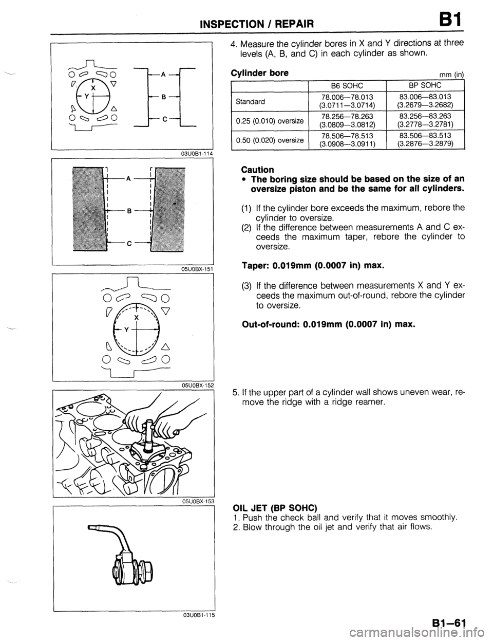
4. Measure the cylinder bores in X and Y directions at three
levels (A, B, and C) in each cylinder as shown.
Cylinder bore mm h-d
I I B6 SOHC I BP SOHC ’ ‘I
,r jtanciard 1 78.006-78.013 1 83.006-83.013
(3.0711-3.0714) (3.2679-3.2682)
0.25 (0.010) oversize 78.256-78.263 83.256-83.263
(3.0809-3.0812) (3.2778-3.2781)
I 0.50 (0.020) oversize 78.506-78.513 83.506-83.513
(3.0908-3.0911) (3.2876-3.2879)
I
Caution
l The boring size should be based on the size of an
oversize piston and be the same for all cylinders.
(1) If the cylinder bore exceeds the maximum, rebore the
cylinder to oversize.
(2) If the difference between measurements A and C ex-
ceeds the maximum taper, rebore the cylinder to
oversize.
Taper: 0.019mm (0.0007 in) max.
(3) If the difference between measurements X and Y ex-
ceeds the maximum out-of-round, rebore the cylinder
to oversize.
Out-of-round: 0.019mm (0.0007 in) max.
5. If the upper part of a cylinder wall shows uneven wear, re-
move the ridge with a ridge reamer.
OIL JET (BP SOHC)
1. Push the check ball and verify that it moves smoothly.
2. Blow through the oil jet and verify that air flows.
81-61