torque MAZDA PROTEGE 1992 Service Manual
[x] Cancel search | Manufacturer: MAZDA, Model Year: 1992, Model line: PROTEGE, Model: MAZDA PROTEGE 1992Pages: 1164, PDF Size: 81.9 MB
Page 124 of 1164

81 INSTALLATION
INSTALLATION
PROCEDURE
Tighten all bolts and nuts to the specified torques.
Step 1
Join the engine and transmission,
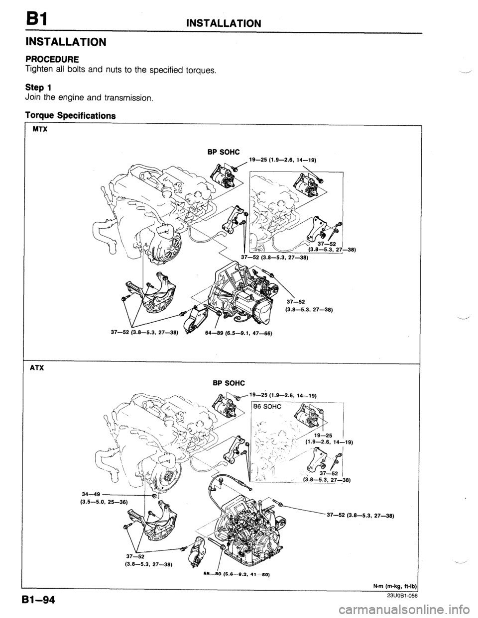
Torque Specifications
MTX
BP SOHC
19-25 (1.9-2.8, 14-19)
W
y
37-52 (3.8-5.3, 27-38)
37-52 (3.8-5.3, 27-38)
84-89 (6.5-9.1, 47-66)
ATX
BP SOHC
19-2ii (1.9-2.8, 14-19)
An
I
y 37-52 /
b ‘i
--< ($8-5.3, 27-36)
34-49
(3.5-S
37-52 (3.8-5.3, 27-38)
Bl--94
S--i0 (5.6-8.2, 41-59)
N.m (m-kg, R-lb)
23UOBl-0%
Page 125 of 1164

INSTALLATION Bl
Step 2
Warning
l Be sure the vehicle is securely supported on safety stands.
Taraue Soecifications
'S-80 (5.6-6.2, 41-59) 74-103 (7.5-10.5, 54-76)
h // 67-93 43-61
(6.8-9.5, 49-69) (4.4-6.2, 32- .45)
64-89 (6.5-9.1, 47-66)'
'
/cR-x&l /84-89 (6.5-9.1, 47-66)
>\----37-L5i (3.8-5.3.
27-38)
N.m (m-kg, ft-II
0311081-i
Ii------ //Ill 1 Engine mount member
1. Install the engine mount member.
Tightening torque:
64-69 N#m (6.5-9.1 m-kg, 47-66 f&lb)
Bl-95
Page 126 of 1164

INSTALLATION
03UOBl-17
No.2 ENGINE /I Ill
03UOBl-171
DYNAMIC DAMPER
03UOBl-17;
03UOBl-178
ATX
1 03UOBl.179
91-96
Engine and transaxle assembly
1. Suspend the engine and transaxle assembly.
Caution
l Do not damage any components in the engine com-
partment.
2. Align the No.1 and No.2 engine mount bolts with the en-
gine mount member mounting holes.
Engine mount
1. Install the No.1 engine mount nut and tighten.
Tightening torque:
37-52 N-m (3.8-5.3 m-kg, 27-38 f&lb)
2. Install the No.2 engine mount nut and tighten.
Tightening torque:
37-52 N-m (3.8-5.3 m-kg, 27-38 ft-lb)
3. Install the engine mount rubber with new washer and tight-
en nut @.
Tightening torque:
74-103 N.m (7.5-10.5 m-kg, 54-76 ft-lb)
4. Install the bolt @, while aligning the engine location and
tighten nut (I!$.
Tightening torque:
67-93 N-m (6.8-9.5 m-kg, 49-69 ft-lb)
5. Install the dynamic damper.
Tightening torque:
55-80 N.m (5.6-8.2 m-kg, 41-59 ft-lb)
6. Install the No.4 engine mount rubber and bracket and loose-
ly tighten nuts @.
7. Align the bracket bolt holes with the body side holes, and
install the bolt @and tighten in the sequence shown in the
figure.
Tightening torque:
43-61 N-m (4.4-6.2 m-kg, 32-45 f&lb)
8. Tighten the nuts @.
Tightening torque: 67-93 N.m (6.6-9.5 m-kg, 49-69 ft-lb)
Page 127 of 1164

Step 3
Torque Specifications
INSTALLATION
ATX
Bl
6.9-11 N-m
(70-110 cm-kg, 61-95 in-lb)
GAs~~~~~~~~c~~~,~
(3.2-4.7, 23-34) 16-23 6.9-9.6 N.m
11.6-2.3. 12-17) (70-100 cm-kg, (4.3-5.6, 31-42) -43)
NEW \.~ 61-67 in-lb)
N.m (m-ka. R-lb
Driveshaft
1. Apply grease to the end of the driveshaft.
Caution
l When installing the driveshaft, be careful not to
damage the oil seal.
l After installation, pull the front hub outward to con-
firm that the driveshaft is securely held by the clip.
2. Install the driveshaft and a new clip.
3. Install the lower arm ball-joint to the knuckle; then tighten
the locknut.
Tightening torque:
43-59 N,rn (4.4-6.0 m-kg, 32-43 f&lb)
Bl-97
Page 128 of 1164

Bl INSTALLATION
Tie-rod end
1. Install the tie-rod end to the knuckle.
Tightening torque:
42-57 N-m (4.3-5.8 m-kg, 31-42 ft-lb)
2. Install the new split pin.
03UOBl.183
,I / 03UOBl-18
Stabilizer
1. Install and adjust the stabilizer.
Dimension @: 17-19mm (0.67-0.75 in)
Extension bar (MTX)
1. Install the extension bar to the transaxle.
Tightening torque:
31-46 N-m (3.2-4.7 m-kg, 23-34 ft-lb)
Shift control rod (MTX)
1. Install the shift control rod to the transaxle.
Tightening torque:
16-23 N.m (I .6-2.3 m-kg, 12-l 7 ft-lb)
Clutch release cylinder (MTX)
1. Install the clutch release cylinder.
Tightening torque:
16-23 N#m (I .6-2.3 m-kg, 12-17 ft-lb)
2. Set the pipe bracket in position.
Tightening torque
@: 6.9-9.8 N.m (70-100 cm-kg, 61-87 in-lb)
@: 16-23 N.m (I .6-2.3 m-kg, 12-17 ft-lb)
Shift control cable (ATX)
1. Install the shift control cable to the transaxle.
Tightening torque:
6.9-l I N-m (70-l IO cm-kg, 61-95 in-lb)
81-98
Page 129 of 1164

INSTALLkTlON Bl
03UOBl-188
03UOBl-18
Step 4
1. Connect the hoses shown in the figure.
Caution Speedometer cable
1. Install the speedometer cable.
Tightening torque:
7.8-l 1 Nom (80-l 10 cm-kg, 69-95 in-lb)
Exhaust pipe
1. Install the exhaust pipe and a gasket; then loosely tighten
the locknuts.
2. Loosely tighten the bracket bolts.
3. Tighten the locknuts.
Tightening torque:
31-46 N-m (3.2-4.7 m-kg, 23-34 ft-lb)
4. Tighten the bracket bolts.
Tightening torque:
37-52 Nmrn (3.8-5.3 m-kg, 27-38 ft-lb)
l Position the hose clamp in the original location on the hose, and squeeze the clamp lightly
with large pliers to ensure a good-fit.
BP SOHC
03UOBl-1s
Bl-9
Page 130 of 1164

Bl INSTALLATION
Step 5
1. Connect the harness connectors shown in the figure.
GROUND ALTERNATOR
OIL PRESSURE SWITCH
I- THFOTTLE SENSOR
NEUTRAL SWITCH (MTX)
IGNITION COIL
$A_c_K;u_p LIGHT SWITCH
____------- ;
Step 6
Torque Specifications
7.8-11 N.m (80-110 cm-kg, 89-95 in-lb)
19-25 (1.9-2.6, 14-19)
2.9-5.9 N.m
(30-60 cm-kg, 26-52 in-lb)
7.8-11 N.m
(80-l 10 cm-kg,
6.4-9.3 N.m 37-52
(3.8-5.3, 27-38)
24-35
(2.4-3.6, 17-26)
7.8-11 N.m 160-110 cmika, 69-95 in-lb) ‘-- -- -..’ ‘-=’ -’ / 166-96 r?m.ka.
66-82 in-lb) 69-95 in-lb)
N.m (m-kg, ft-lb -- OBUOBl-1E
Bl-100
Page 131 of 1164

INSTALLATION Bl
I I
03UOBl-193
03UOBl-19
1
PULLEY
P/S AND A/C
OWOBl-19
03UOBl-15
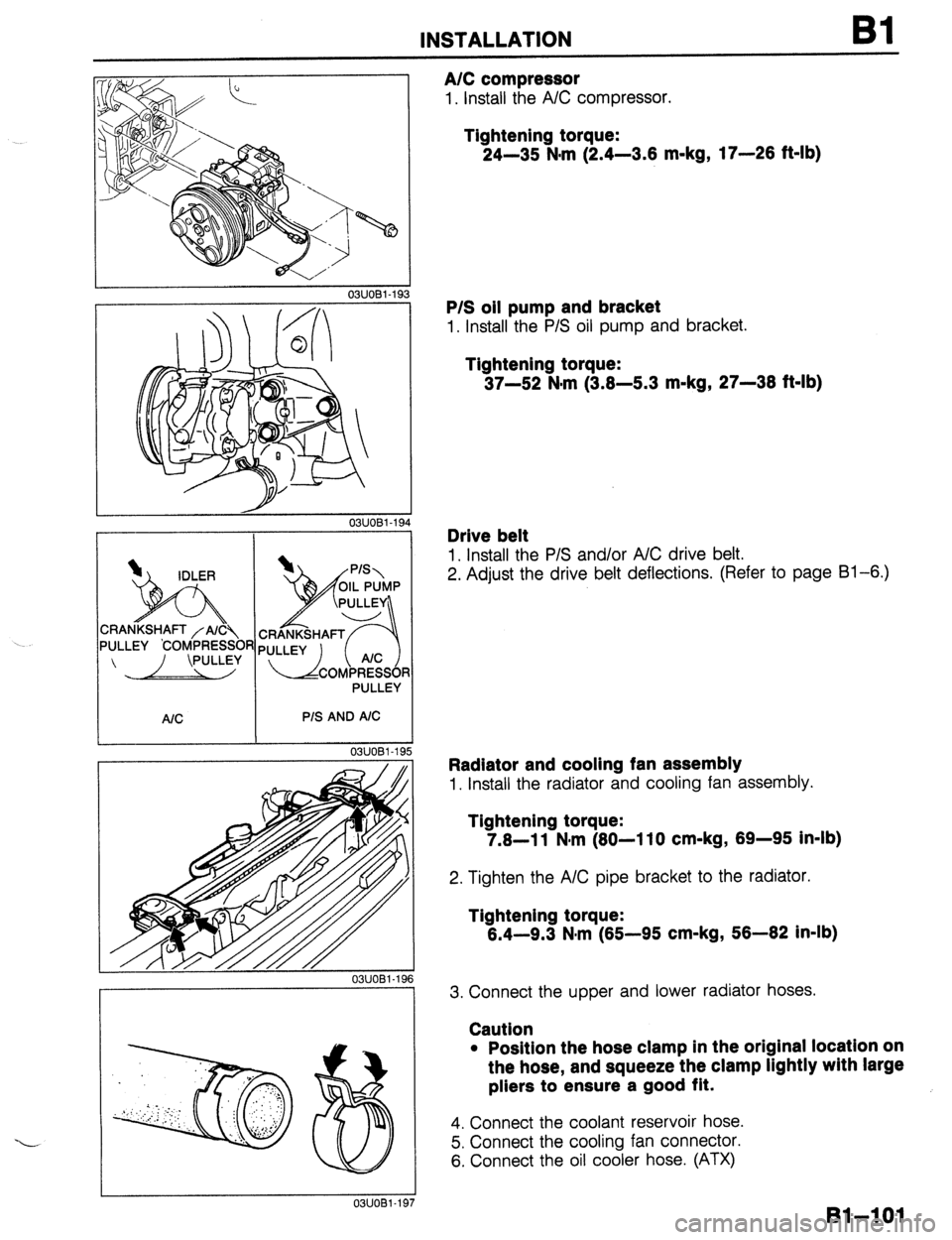
A/C compressor
1. Install the A/C compressor.
Tightening torque:
24-35 N-m (2.4-3.6 m-kg, 17-26 ft-lb)
P/S oil pump and bracket
1. Install the P/S oil pump and bracket.
Tightening torque:
37-52 N-m (3.6-5.3 m-kg, 27-36 ft-lb)
Drive belt
1. Install the P/S and/or A/C drive belt.
2. Adjust the drive belt deflections. (Refer to page Bl-6.)
Radiator and cooling fan assembly
1. Install the radiator and cooling fan assembly.
Tightening torque:
7.6-11 N#m (60-110 cm-kg, 69-95 in-lb)
2. Tighten the A/C pipe bracket to the radiator.
Tightening torque:
6.4-9.3 N*rn (65-95 cm-kg, 56-62 in-lb)
3. Connect the upper and lower radiator hoses.
Caution
l Position the hose clamp in the original location on
the hose, and squeeze the clamp lightly with large
pliers to ensure a good fit.
4. Connect the coolant reservoir hose.
5. Connect the cooling fan connector.
6. Connect the oil cooler hose. (ATX)
Bl-=lOl
Page 132 of 1164

INSTALLATION
OWOBX-27!
Resonance chamber
1. Install the resonance chamber.
Tightening torque:
7.8-l 1 N-m (80-I 10 cm-kg, 69-95 in-lb)
Undercover and side cover
1. Install the undercover and side cover.
Steps After Installation
1. If the engine oil was drained, fill with the specified amount and type of engine oil.
(Refer to Section D.)
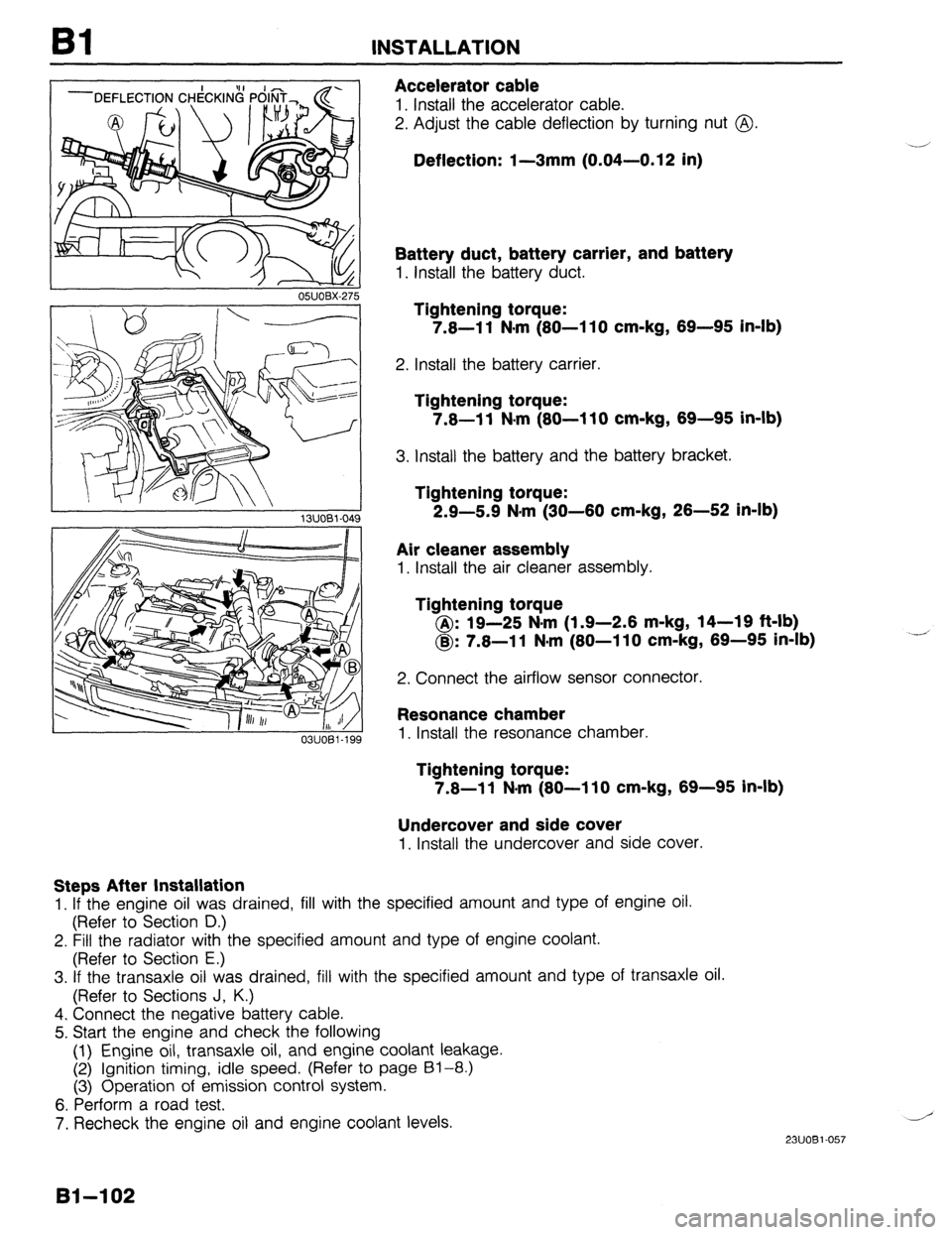
Accelerator cable
1. Install the accelerator cable.
2. Adjust the cable deflection by turning nut @.
Deflection: I-3mm (0.04-0.12 in)
Battery duct, battery carrier, and battery
1. Install the battery duct.
Tightening torque:
7.8-l 1 N-m (80-l 10 cm-kg, 69-95 in-lb)
2. Install the battery carrier.
Tightening torque:
7.8-11 N.m (80-110 cm-kg, 69-95 in-lb)
3. Install the battery and the battery bracket.
Tightening torque:
2.9-5.9 N*m (30-60 cm-kg, 26-52 in-lb)
Air cleaner assembly
1. Install the air cleaner assembly.
lightening torque
@: 19-25 N-m (1.9-2.6 m-kg, 14-19 ft-lb)
@: 7.8-l 1 N-m (80-I 10 cm-kg, 69-95 in-lb)
2. Connect the airflow sensor connector.
2. Fill the radiator with the specified amount and type of engine coolant.
(Refer to Section E.)
3. If the transaxle oil was drained, fill with the specified amount and type of transaxle oil.
(Refer to Sections J, K.)
4. Connect the negative battery cable.
5. Start the engine and check the following
(1) Engine oil, transaxle oil, and engine coolant leakage.
(2) Ignition timing, idle speed. (Refer to page 61-8.)
(3) Operation of emission control system.
6. Perform a road test,
7. Recheck the engine oil and engine coolant levels.
.-’
23UOBl-057
81-102
Page 134 of 1164

82 INDEX
NDEX
COMPRESSION INSPECTION, PAGE 92-10
STANDARD: 1,256 kPa (12.8 kg/cm2, 182 psi)-300 rpm
MINIMUM: 883 kPa (9.0 kg/cm2, 128 psi)-300 rpm
INTAKE MANIFOLD
TIGHTENING TORQUE
*(I-I)* hl.m I, (I-0 c m.h.
DRIVE BELT
ADJUSTMENT, PAGE 82-6 TIGHTENIF
36-46 N.m (3.9-4.7 rlG TORQUE
m-kg, 26-34 ft-lb)
JEFLECTION
mm (in)
DRIVE BELT
New Used Limit
ALTERNATOR
8.0-9.0 (0.31-0.35) 9.0-10.0 (0.35-0.39)
12.5 (0.49)
PIS, PIS + AIC 8.0-9.0 (0.31-0.35) 9.0-10.0 (0.35-0.39)
11.5 (0.45)
23UOB2-00:
1. Timing belt
6. Engine
Removal I Installation..
..............
page 62-l 2 Removal ...................................
page 82-31
2. Cylinder head gasket
Engine stand mounting..
.......... page 82-38
Replacement ............................
page B2-16 Disassembly
.............................
page 82-41
3. HLA
Inspection / Repair.. ..................
page B2-54
Removal / Installation
................ page
82-22 Assembly ..................................
page B2-66
4. Front oil seal
Engine stand dismounting
....... page 62-91
Replacement
page 82-26 Installation..
.-- ............................
............................... page 62-93
5. Rear oil seal
Replacement ............................
page 82-28
82-2