torque MAZDA PROTEGE 1992 Repair Manual
[x] Cancel search | Manufacturer: MAZDA, Model Year: 1992, Model line: PROTEGE, Model: MAZDA PROTEGE 1992Pages: 1164, PDF Size: 81.9 MB
Page 139 of 1164

ENGINE TUNE-UP PROCEDURE 92
23UOB2-OC
DRIVE PULLEY
I I
2311082.010
HLA
I Problem
1. Noise when engine is started immedi-
ately after oil is changed.
2. Noise when engine is started after set-
tina aporox. one dav.
3. Noise when engine is started after
cranking for 3 seconds or more.
4. Noise when engine is started after
new HLA is installed.
5. Noise continues more than 10 minutes
6. Noise occurs durning idle after high-
“”
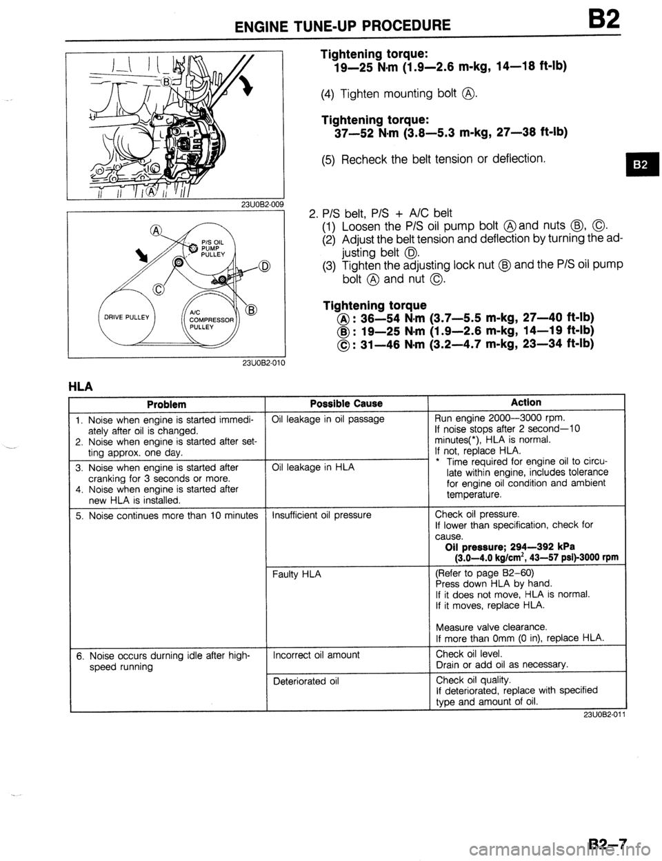
Tightening torque:
19-25 N.m (1.9-2.6 m-kg, 14-16 ft-lb)
(4) Tighten mounting bolt @.
Tightening torque:
37-52 N#rn (3.6-5.3 m-kg, 27-36 ft-lb)
(5) Recheck the belt tension or deflection.
2. P/S belt, P/S + A/C belt
(1) Loosen the P/S oil pump bolt @and nuts @, 0.
(2) Adjust the belt tension and deflection by turning the ad-
justing belt 0.
(3) Tighten the adjusting lock nut @J and the P/S oil pump
bolt @ and nut 0.
Tightening torque
@: 36-54 N-m (3.7-5.5 m-kg, 27-40 ft-lb)
@ : 19-25 N*m (1.9-2.6 m-kg, 14-19 ft-lb)
0: 31-46 N-m (3.2-4.7 m-kg, 23-34 ft-lb) Possible Cause
Oil leakage in oil passage
Oil leakage in HLA
Insufficient oil pressure
Faulty HLA
Incorrect oil amount
Deteriorated oil Action Run engine 2000-3000 rpm.
If noise stops after 2 second-10
minutes(*), HLA is normal.
If not, replace HLA.
* Time required for engine oil to circu-
late within engine, includes tolerance
for engine oil condition and ambient
temperature.
Check oil pressure.
If lower than specification, check for
cause. Oil pressure; 294-392 kPa
(3.0-4.0 kg/cm’, 43-57 psi)-3000 rpm
(Refer to page 82-60)
Press down HLA by hand.
If it does not move, HLA is normal.
If it moves, replace HLA.
Measure valve clearance.
If more than Omm (0 in), replace HLA.
Check oil level.
Drain or add oil as necessary.
Check oil quality.
If deteriorated, replace with specified
type and amount of oil.
2311082-01
B2-7
Page 140 of 1164

82 ENGINE TUNE-UP PROCEDURE
03UOB2-013
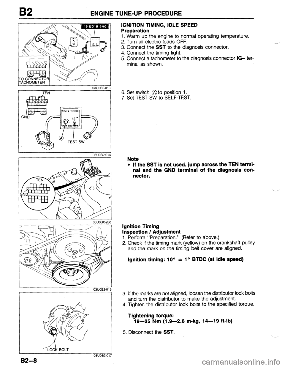
IGNITION TIMING, IDLE SPEED
Preparation
1. Warm up the engine to normal operating temperature.
2. Turn all electric loads OFF.
3. Connect the
SST to the diagnosis connector.
4. Connect the timing light.
5. Connect a tachometer to the diagnosis connector
IO- ter-
minal as shown.
TEN
03UOB2-01
I
-&k BOLT
0311082-01’
82-8
6. Set switch @to position 1.
7. Set TEST SW to SELF-TEST.
Note
l If the SST is not used, jump across the TEN termi-
nal and the GND terminal of the diagnosis con-
nector.
Ignition Timing
Inspection / Adjustment
1. Perform “Preparation.” (Refer to above.)
2. Check if the timing mark (yellow) on the crankshaft pulley
and the mark on the timing belt cover are aligned.
Ignition timing: 10 * f lo BTDC (at Idle speed)
3. If the marks are not aligned, loosen the distributor lock bolts
and turn the distributor to make the adjustment.
4. Tighten the distributor lock bolts to the specified torque.
Tightening torque:
19-25 N*m (1 .Q-2.6 m-kg, 14-19 ft-lb)
5. Disconnect the SST.
Page 142 of 1164

B2 COMPRESSION
COMPRESSION
If the engine exhibits low power, poor fuel economy, or poor idle, check the following:
1, Ignition system (Refer to Section G.)
2. Compression
3. Fuel system (Refer to Section F.)
23UOB2-013
13UOl32.004
2311087-014
-_
B2-10
2311082-012
INSPECTION
1. Check that the battery is fully charged. Recharge it if neces-
sary. (Refer to Section G.)
2. Warm up the engine to normal operating temperature.
3. Turn the engine OFF.
4. Remove all spark plugs.
5, Disconnect the ignition coil connector.
6. Connect a compression gauge to the No.1 spark plug hole.
7. Fully depress the accelerator pedal and crank the engine.
8. Record the maximum gauge reading.
9. Check each cylinder.
Compression:
1,256 kPa (12.6 kg/cm’, 182 psi)-300 rpm
Minimum:
883 kPa (9.0 kg/cm2, 128 psi)-300 rpm
Max. difference between cylinders:
196 kPa (2.0 kg/cm2, 28 psi)
10. If the compression in one or more cylinders is low, pour a
small amount of engine oil into the cylinder and recheck
the compression.
(1) If the compression increases, the piston, piston rings,
or cylinder wall may be worn.
(2) If the compression stays low, the valve may be stuck
or seating improperly.
(3) If the compression in adjacent cylinders stays low, the
cylinder head gasket may be defective or the cylinder
head distorted.
Il. Connect the ignition coil connector.
12. Install the spark plugs.
05UOBX-020
Tightening torque:
15-23 N*m (1.5-2.3 m-kg, 11-17 ft-lb)
Page 147 of 1164

ON-VEHICLE MAINTENANCE
13EOB2-015
DEFLECTION CHECKING POINT
13EOE2-011
23UOB2-017
23UOB2-018
Steps After Installation
1. Connect the negative battery cable.
2. Start the engine and check as follows:
l Ignition timing. (Refer to page B2-8.) 10. Loosen the tensioner lock bolt to apply spring tension to
the timing belt.
11. Tighten the tensioner lock bolt.
Tightening torque:
37-52 Narn (3.8-5.3 m-kg, 27-38 ft-lb)
12. Install the pulley boss and pulley lock bolt.
13. Turn the crankshaft 2 and 116 turns clockwise and verify
that the timing marks are correctly aligned.
14. Measure the timing belt deflection by applying moderate
pressure (98 N,
10 kg, 22 lb) midway between the cam-
shaft pulleys.
If the deflection is not correct, repeat from Step 10 above.
Deflection:
9.0-11.5mm (0.35-0.45 In) at 98 N (10 kg, 22 lb)
Spark plug
1. Install the spark plugs.
Tightening torque:
15-23 Nern (1.5-2.3 m-kg, 11-17 ft-lb)
Pulley lock bolt
1, Hold the crankshaft with the SST and tighten the pulley lock
bolt.
Tightening torque:
157-187 N*rn (18-17 m-kg, 118-123 ft-lb)
23UOB2-019
82-l 5
Page 151 of 1164

ON-VEHICLE MAINTENANCE B2
- 05UOBX-04:
---_____~
OWOBX 04
----
05UOBX-03
4
2. Loosen the tensioner lock bolt.
Caution
l To prevent damage to the tensioner, secure it with
a rag.
3. Temporarily secure the tensioner with the spring fully ex-
tended.
Caution
Q Do not allow any oil or grease on the timing belt.
4. Remove the timing belt and secure it out of the way to pre-
vent damage during removal and installation of the cylin-
der head.
Cylinder head bolt
1. Loosen the cylinder head bolts in two or three steps in the
order shown in the figure.
2. Remove the cylinder head bolts.
Installation note
Cylinder head bolt
1. Apply clean engine oil to the bolt threads and seat faces.
2. Install the cylinder head bolts.
3. Tighten the cylinder head bolts in two or three steps in the
order shown in the figure.
Tightening torque:
76-81 N-m (7.7-8.3 m-kg, 56-60 ft-lb)
Cylinder head cover
1, Apply silicone sealant to the shaded areas as shown in the
figure.
2. Install the cylinder head cover.
Tightening torque:
4.9-8.8 N-m (50-90 cm-kg, 43-78 in-lb)
B2-19
Page 152 of 1164

B2 ON-VEHICLE MAINTENANCE
03UOB2-033
FOUR TEETH
13UOB2-015
05UOBX-032
B2-20
Timing belt
1. Check that the ignition timing mark (yellow) on the crank-
shaft pulley and the timing mark on the timing belt cover
are aligned.
2. Verify that the camshaft pulley marks are aligned with the
seal plate marks.
Caution
l For intake side, align the I mark.
l For exhaust side, align the E mark.
3. Install the timing belt so that there is no looseness at the
idler side or between the two camshaft pulleys.
Caution
l Do not turn the crankshaft counterclockwise.
4. Turn the crankshaft two turns clockwise, and align the tim-
ing belt pulley mark with the timing mark.
5. Verify that the camshaft pulley marks are aligned with the
seal plate marks.
If not aligned, remove the timing belt and repeat from ten-
sioner installation.
6. Turn the crankshaft 1 and 5/6 turns clockwise, and align
the fourth tooth from the
I mark with the seal plate mark.
7. Loosen the tensioner lock bolt to apply tension to the tim-
ing belt.
8. Tighten the tensioner lock bolt.
Tightening torque:
37-52 N#rn (3.8-5.3 m-kg, 27-38 ft-lb)
9. Turn the crankshaft 2 and l/6 turns clockwise and verify
that the timing marks are correctly aligned.
Page 156 of 1164

ON-VEHICLE MAINTENANCE
OWOBX-05.
OxJOBX-05,
ENOBX-056
--
Caution
l Do not allow any sealant on the camshaft journal
surfaces.
.-
3. Apply silicone sealant to the shaded areas shown in the
figure.
4. Install the camshaft caps according to the cap number and
arrow mark.
5. install the camshaft cap bolts and tighten them in two or
three steps in the order shown in the figure.
Tightening torque:
11.3-l 4.2 N-m (1 .15--l .45 m-kg, loo-126 in-lb)
6. Apply a small amount of clean engine oil to the lip of a new
camshaft oil seal.
7. Push the oil seal slightly in by hand.
Caution
l The oil seal must be tapped in until it is flush with
the edge of the camshaft cap.
8. Tap the oil seal in evenly with a suitable pipe and a hammer.
Oil seal outer diameter: 46mm (1.69 in)
Camshaft pulley
1. Turn the camshafts until the camshaft dowel pins face
straight up.
2. Install the camshaft pulleys with the I mark (intake side) or
the E mark (exhaust side) straight up.
I II’- ,
J
05UOBX-057
B2-24
Page 157 of 1164

ON-VEHICLE MAINTENANCE B2
05UOBX-05
BLA-DE 0-dlNG
Steps After Installation
1. Connect the negative battery cable.
2. Start the engine and check as follows:
l Ignition timing. (Refer to page 82-8.) 3. Install the camshaft pulley lock bolts.
4. Hold the camshaft with a wrench.
5. Tighten the camshaft pulley lock bolt.
Tightening torque:
49-61 N-m (5.0-6.2 m-kg, 36-45 ft-lb)
Distributor
1. Apply grease to a new O-ring and the blade.
2. Install the distributor and loosely tighten the installation bolt.
3. Connect the distributor connector.
0311082-039
B2-25
Page 159 of 1164

ON-VEHICLE MAINTENANCE
I 05UOBX-063
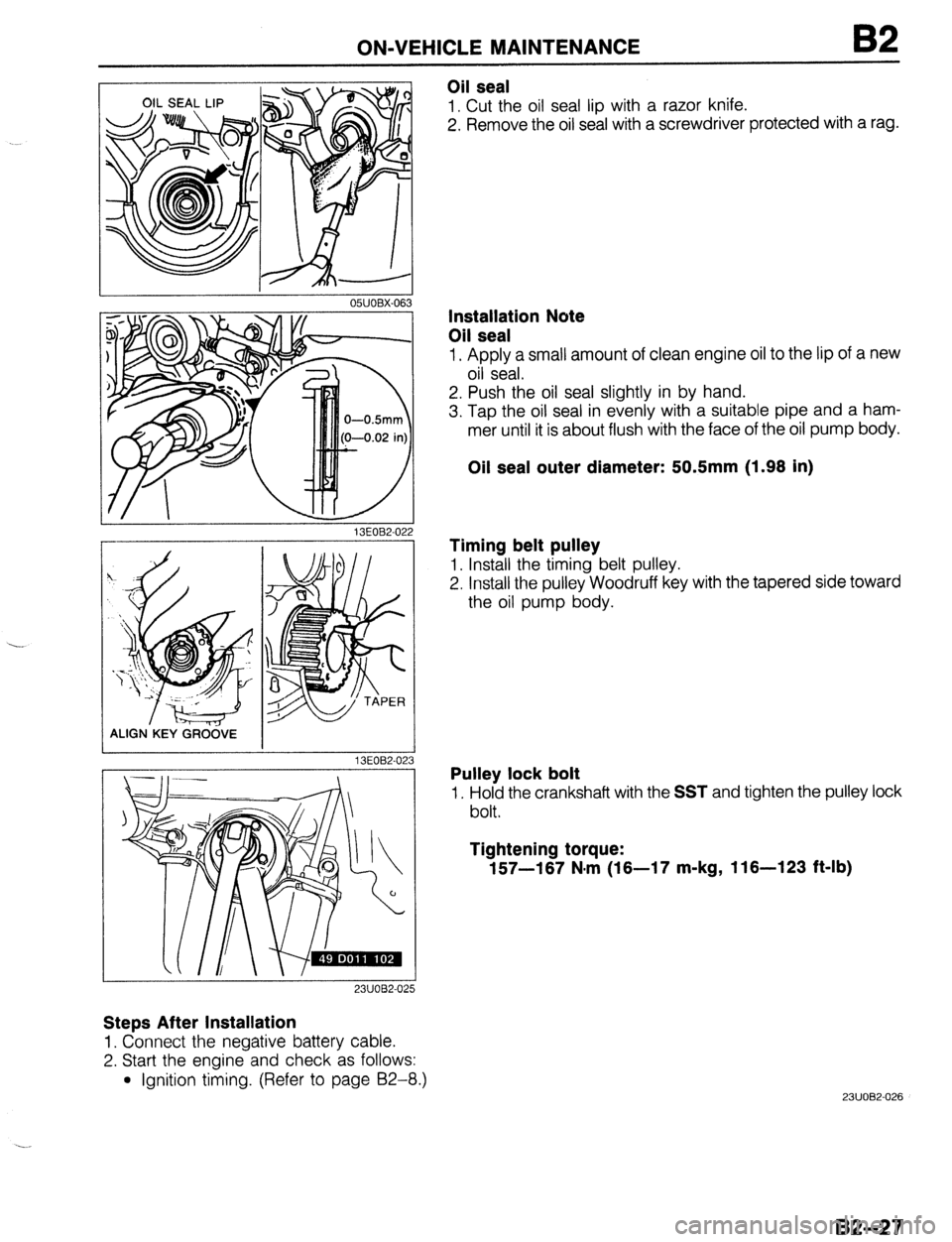
Oil seal
1. Cut the oil seal lip with a razor knife.
2. Remove the oil seal with a screwdriver protected with a rag.
13EOB2-02
ALIGN.KEY GRCi&E
13EOB2-02
23UOB2-025
Steps After Installation
1. Connect the negative battery cable.
2. Start the engine and check as follows:
l Ignition timing. (Refer to page 92-8.)
3
Installation Note
Oil seal
1. Apply a small amount of clean engine oil to the lip of a new
oil seal.
2. Push the oil seal slightly in by hand.
3. Tap the oil seal in evenly with a suitable pipe and a ham-
mer until it is about flush with the face of the oil pump body.
Oil seal outer diameter: 50.5mm (1.98 in)
Timing belt pulley
1. Install the timing belt pulley.
2. Install the pulley Woodruff key with the tapered side toward
the oil pump body.
Pulley lock bolt
1. Hold the crankshaft with the SST and tighten the pulley lock
bolt.
Tightening torque:
157-187 N.m (18-17 m-kg, 116-123 ft-lb)
23UOB2-026
82-27
Page 161 of 1164

ON-VEHICLE MAINTENANCE
Drive plate (ATX)
1. Hold the drive plate with the SST or equivalent.
2. Remove the drive plate lock bolts.
3. Remove the backing plate, drive plate, and adapter.
2311082-052
I
Oil seal
1. Cut the oil seal lip with a razor knife.
2. Remove the oil seal with a screwdriver protected with a rag.
I I
I
05UOBX-063
Installation note
Oil seal
1, Apply a small amount of clean engine oil to the lip of a new
oil seal.
2. Push the oil seal slightly in by hand.
OWOBX-069
APPLY SEALANT
03UOB2.04
Caution
l The oil seal must be tapped in untjl it is flush with
the edge of the rear cover.
3. Tap the oil seal in evenly with a suitable pipe and a hammer.
Oil seal outer diameter: 1OOmm (3.94 in)
Flywheel (MTX)
1. Remove the sealant from the flywheel bolt holes in the crank-
shaft and from the flywheel bolts.
Caution
l If all the previous sealant cannot be removed from
a bolt, replace the bolt.
l Do not apply sealant if a new bolt is used.
2. Set the flywheel onto the crankshaft.
3. Apply sealant to the flywheel bolts and install them.
4. Hold the flywheel with the
SST or equivalent.
5. Tighten the bolts in two or three steps in the order shown
in the figure.
Tightening torque:
1 96-103 N-m (9.6-10.5 m-kg, 71-76 ft-lb)
2311082-053
B2--29