sensor MAZDA PROTEGE 1992 Repair Manual
[x] Cancel search | Manufacturer: MAZDA, Model Year: 1992, Model line: PROTEGE, Model: MAZDA PROTEGE 1992Pages: 1164, PDF Size: 81.9 MB
Page 435 of 1164

CONTROL SYSTEM F
03UOFX-22
RESISTANCE
WI
THROTTLE VALVE
OPENING ANGLE
FULLY bPEN
03UOFX-22
03UOFX-2i
THROTTLE SENSOR
Inspection (MTX)
1. Disconnect the connector from the throttle sensor.
2. Connect an ohmmeter to the throttle sensor.
3. Insert a feeler gauge between the throttle stop screw and
the stop lever and check the continuity between terminals.
Feeler gauge Continuity between terminals
IDL - E
1 POW * E
O.lmm (0.004 in)
1 .Omm (0.039 in)
Wide-open throttle Yes
No
No No
No
Yes
Inspection (ATX)
1. Disconnect the connector from the throttle sensor.
2. Connect an ohmmeter between the throttle sensor termi-
nals E and IDL.
3. Insert a feeler gauge between the throttle stop screw and
the stop lever.
4. Check the continuity between terminals.
Feeler gauge
0.1 mm (0.004 in)
0.6mm (0.024 in) Continuity
Yes
No
5. Connect an ohmmeter to the throttle sensor terminal VT
and E.
6. Verify that the resistance increases lineally according to throt-
tle valve opening angle.
Throttle valve condition Resistance (W)
Fully closed Below 1
Fully open Approx. 5
Adjustment (MTX)
1. Disconnect the connector from the throttle sensor.
2. Connect an ohmmeter to the throttle sensor terminals IDL
and E.
3. Insert a 0.4mm (0.016 In) feeler gauge between the throt-
tle stop screw and the stop lever.
F-l 69
Page 436 of 1164

F CONTROL SYSTEM
0.7mm (0
GAUGE
1 SUOFX-10 3 03UOFX-235
03UOFX.22 5 IDL
E
03UOFX-22t 5
4. Loosen the two attaching screws.
5. Rotate the throttle sensor clockwise
approx. 30 degrees,
then rotate it back counterclockwise until the continuity
exists.
6. Replace the feeler gauge with a
0.7mm (0.027 in) gauge.
7. Verify that the continuity does not exist.
8. If it exists, repeat Steps 3 through 6. ‘-
9. Tighten the two attaching screws.
Note
l Do not move the throttle sensor from the set posi-
tion when tightening the screws.
10. Open the throttle valve fully a few times.
11. Recheck the adjustment of the throttle sensor.
Adjustment (ATX)
1. Disconnect the connector from the throttle sensor.
2. Connect an ohmmeter between the throttle sensor termi-
nals E and IDL.
3. Loosen the two attaching screws.
4. Insert a
0.25mm (0.01 in) feeler gauge between the throt-
tle stop screw and the stop lever.
5. Rotate the throttle sensor clockwise
approx. 30 degrees,
then rotate it back counterclockwise until there is continuity. i-
6. Replace the feeler gauge with a
0.4mm (0.016 in) gauge
and verify that there is no continuity.
7. If there is continuity, repeat Steps 4 through 6.
8. Tighten the two attaching screws.
Note
l Do not move the throttle sensor from the set posi-
tion when tightening the screws.
9. Open the throttle valve fully and verify that the resistance
between the throttle sensor terminals E and VT is
approx.
5 kQ.
F-l 70
Page 437 of 1164
CONTROL SYSTEM F
03UOFX-227
03UOFX-22:
03UOFX-22!
*
03UOFX-231
I
SELF-W CtECXER
WOFX-15
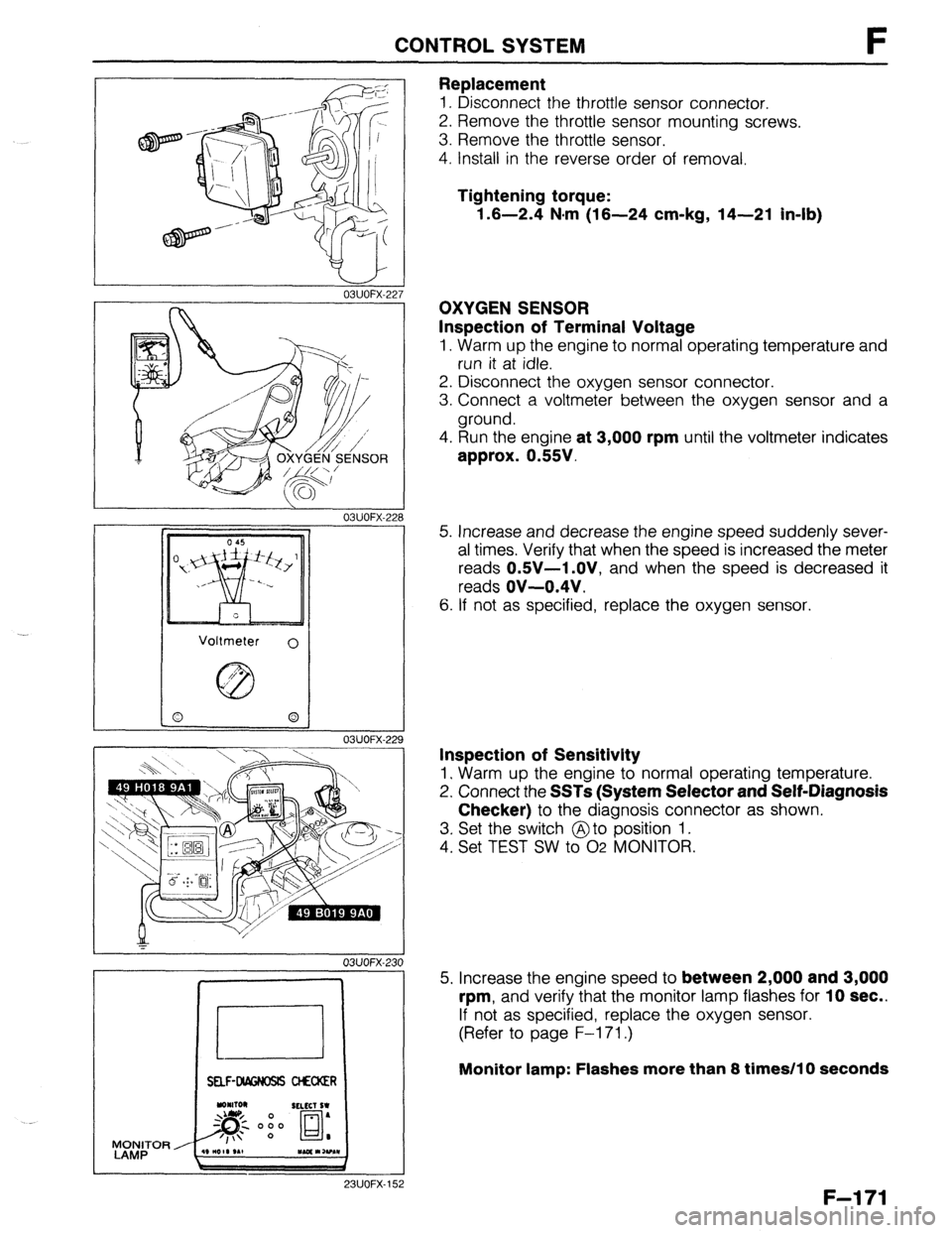
Replacement
1. Disconnect the throttle sensor connector.
2. Remove the throttle sensor mounting screws.
3. Remove the throttle sensor.
4. Install in the reverse order of removal.
Tightening torque:
1.6-2.4 N-m (16-24 cm-kg, 14-21 in-lb)
OXYGEN SENSOR
Inspection of Terminal Voltage
1. Warm up the engine to normal operating temperature and
run it at idle.
2. Disconnect the oxygen sensor connector.
3. Connect a voltmeter between the oxygen sensor and a
ground.
4. Run the engine
at 3,000 rpm until the voltmeter indicates
approx. 0.55V.
5. Increase and decrease the engine speed suddenly sever-
al times. Verify that when the speed is increased the meter
reads
OSV-1 .OV, and when the speed is decreased it
reads
OV-0.4V.
6. If not as specified, replace the oxygen sensor.
Inspection of Sensitivity
1. Warm up the engine to normal operating temperature.
2. Connect the
SSTs (System Selector and Self-Diagnosis
Checker)
to the diagnosis connector as shown.
3. Set the switch @to position 1.
4. Set TEST SW to 02 MONITOR.
5. Increase the engine speed to
between 2,000 and 3,000
rpm,
and verify that the monitor lamp flashes for 10 sec..
If not as specified, replace the oxygen sensor.
(Refer to page F-l 71.)
Monitor lamp: Flashes more than 8 times/l 0 seconds
F-l 71
Page 438 of 1164
F CONTROL SYSTEM
23UOFX-15
23UOFX-15
23UOFX-15
LOCK
4
I
13UOFX-oc
F-l 72
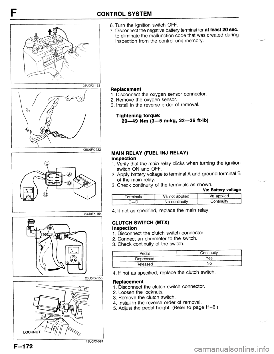
6. Turn the ignition switch OFF.
7. Disconnect the negative battery terminal for
at least 20 sec.
to eliminate the malfunction code that was created during
inspection from the control unit memory.
Replacetnent
1. Disconnect the oxygen sensor connector.
2. Remove the oxygen sensor.
3. Install in the reverse order of removal.
Tightening torque:
29-49 N-m (3-5 m-kg, 22-36 ft-lb)
MAIN RELAY (FUEL INJ RELAY)
Inspection
1. Verify that the main relay clicks when turning the ignition
switch ON and OFF.
2. Apply battery voltage to terminal A and ground terminal E3
of the main relay.
3. Check continuity of the terminals as shown.
VB: Battery voltage
Terminals 1 Ve not applied VB applied
C-D No continuity Continuity
4. If not as specified, replace the main relay.
CLUTCH SWITCH (MTX)
Inspection
1, Disconnect the clutch switch connector.
2. Connect an ohmmeter to the switch.
3. Check continuity of the switch.
Pedal Continuity
Depressed Yes
Released No
4. If not as specified, replace the clutch switch. ,
Replacement
1. Disconnect the clutch switch connector.
2. Loosen the locknuts.
3. Remove the clutch switch.
4. Install in the reverse order of removal.
5. Adjust the pedal height. (Refer to page H-6.)
Page 462 of 1164
\jl IGNITION SYSTEM
1.6-3.0 N.m
(16-30 cm-Fg,
14-26 in-lb)
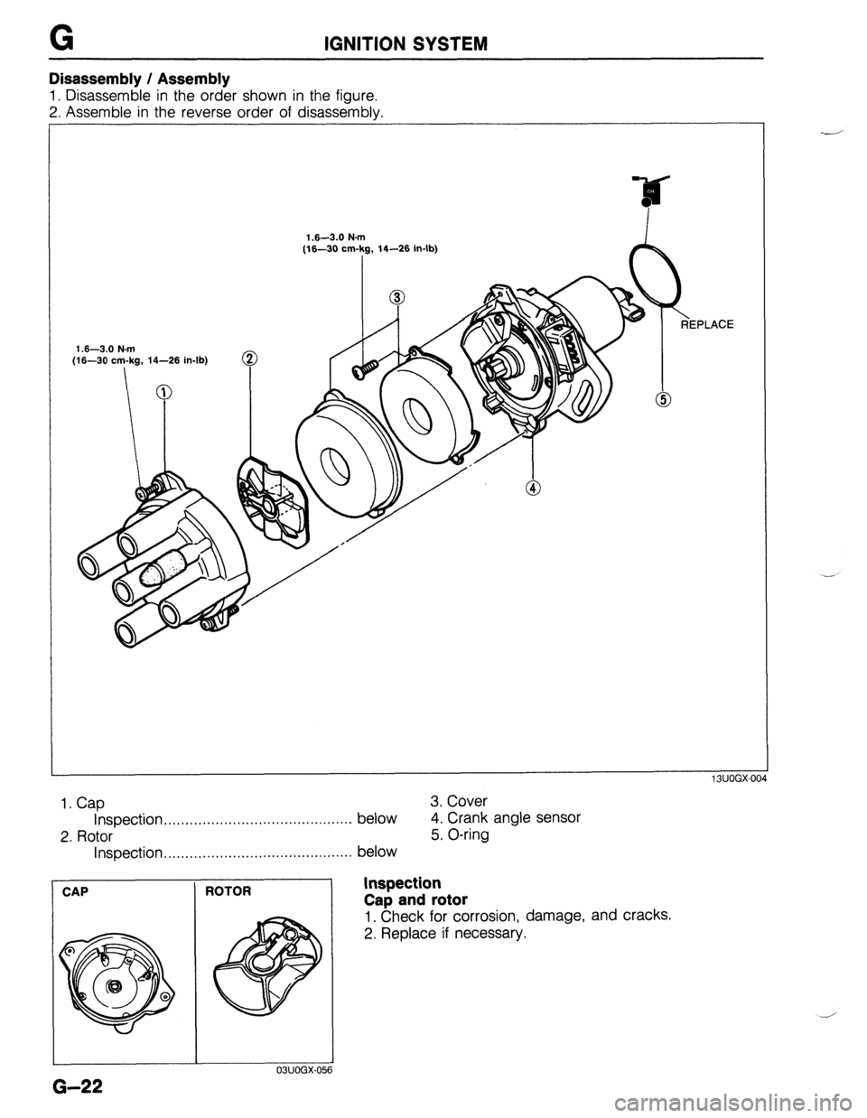
Disassembly / Assembly
1. Disassemble in the order shown in the figure.
2. Assemble in the reverse order of disassembly.
1 BUOGX-00.
1. Cap
3. Cover
Inspection . . . . . . . . . . . . . . . . . . . . . . . ..*..................
below 4. Crank angle sensor
2. Rotor
5. O-ring
Inspection .,..........................................
below
CAP
G-22
I
ROTOR
I 03UOGX.051 ?
REPLACE
Inspection
Cap and rotor
1. Check for corrosion, damage, and cracks.
2. Replace if necessary.
Page 669 of 1164
OUTLINE
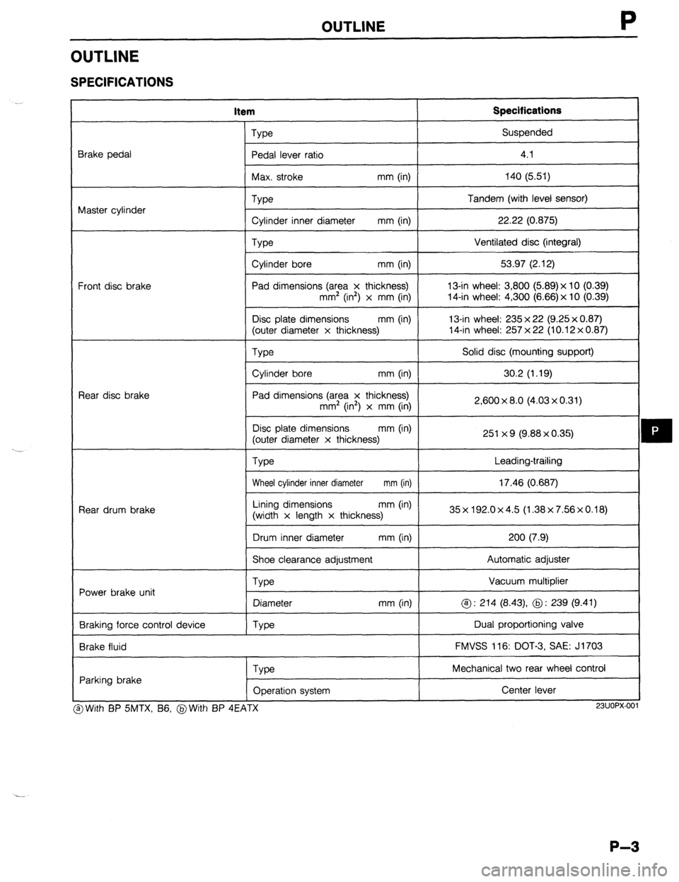
OUTLINE
SPECIFICATIONS
item Specifications
Brake pedal
Master cylinder
Front disc brake
Rear disc brake
Rear drum brake
Power brake unit
Braking force control device
Brake fluid Type Suspended
Pedal lever ratio
I 4.1
I
Max. stroke mm (in) 140 (5.51)
I
Type
Cylinder inner diameter mm (in)
Type
Cylinder bore mm (in)
Pad dimensions (area x thickness)
mm’ (in2) x mm (in)
Disc plate dimensions mm (in)
(outer diameter x thickness) Tandem (with level sensor)
22.22 (0.875)
Ventilated disc (integral)
53.97 (2.12)
13-in wheel: 3,800 (5.89)x 10 (0.39)
14-in wheel: 4,300 (6.66) x 10 (0.39)
13-in wheel: 235 x 22 (9.25 x 0.87)
14-in wheel: 257 x 22 (10.12 x 0.87)
We
I Solid disc (mounting support)
I
Cylinder bore mm (in)
I 30.2 (1.19)
I
Pad dimensions (area x thickness)
mm2 (in’) x mm (in)
Disc plate dimensions mm (in)
(outer diameter x thickness)
Type 2,600 x 8.0 (4.03 x 0.31)
251 x 9 (9.88 x 0.35)
Leading-trailing
Wheel cylinder inner diameter mm (in) 17.46 (0.687)
I
Lining dimensions mm (in)
(width x length x thickness) 35x192.0x4.5 (1.38x7.56x0.18)
I
Drum inner diameter mm (in) 200 (7.9)
I
Shoe clearance adjustment Automatic adjuster
Vacuum multiplier
@ : 214 (8.43) @ : 239 (9.41)
Dual proportioning valve
FMVSS 116: DOT-3, SAE: J1703
Type
Diameter
Type mm (in)
Parking brake
Type
Operation system Mechanical two rear wheel control
Center lever I
3 With BP SMTX, B6, @With BP 4EATX
I I
23UOPX-001
P-3
Page 678 of 1164

P CONVENTIONAL BRAKE SYSTEM
Disassembly / Assembly / Inspection
1. After removing the brake fluid, disassemble in the order shown in the figure.
2. Inspect all parts and repair or replace as necessary.
3. Assemble in the reverse order of disassembly.
Caution
l Secure the master cylinder flange in a vise when necessary.
l Replace the piston assembly, if necessary.
l Do not let foreign material enter the cylinder, and do not scratch the inside of the cylinder
or the outer surface of the piston.
REP1 .ACE
0.98-1.47 (10-15, 8.7-13.0)
o R,NG ,,,dcE @.96-2.45 (20-25, 17.4-21.7)
- 3
N.m (cm-kg, in-lb)
1. Reservoir cap assembly 5. Bushing 9. Primary piston assembly
2. Float 6. Stopper screw 10. Secondary piston assembly
3. Screw 7. Fluid level sensor 11. Master cylinder body
4. Reservoir 8. Snap ring
P-12
Page 737 of 1164
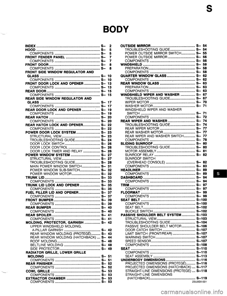
S
BODY
INDEX ........................................................ 2
HOOD ........................................................
COMPONENTS ........................................ t
FRONT FENDER PANEL .............................. ;I
COMPONENTS ........................................ S- ::
FRONT DOOR ............................................. S- 8
COMPONENTS ........................................ S- 8
FRONT SIDE WINDOW REGULATOR AND
GLASS ..................................................... s- 10
COMPONENTS ........................................ s- 10
FRONT DOOR LOCK AND OPENER .............. S- 13
COMPONENTS ........................................ s- 13
REAR DOOR ............................................... s- 15
COMPONENTS ........................................ s- 15
REAR SIDE WINDOW REGULATOR AND
GLASS ..................................................... s- 17
COMPONENTS ........................................ s- 17
REAR DOOR LOCK AND OPENER ...........
.-. ...
S- 19
COMPONENTS ........................................ s- 19
REAR HATCH ............................................. s- 20
COMPONENTS ........................................ s- 20
REAR HATCH LOCK AND OPENER.. .............
S- 22
COMPONENTS ........................................ s- 22
POWER DOOR LOCK SYSTEM.. ................... S- 23
STRUCTURAL VIEW .................................. S- 23
TROUBLESHOOTING GUIDE ...................... S- 24
DOOR LOCK SWITCH ............................... S- 28
DOOR LOCK CONTROL ............................ S- 26
DOOR LOCK TIMER AND RELAY ............... S- 26
POWER WINDOW SYSTEM .......................... S- 27
STRUCTURAL VIEW .................................. S- 27
TROUBLESHOOTING GUIDE.. .................... S- 28
MAIN POWER WINDOW SWITCH.. .............. S- 31
POWER WINDOW SUB-SWITCH.. ................ S- 32
POWER WINDOW MOTOR ......................... S- 32
TRUNK LID .................................................
s- 33
COMPONENTS ........................................ s- 33
TRUNK LID LOCK AND OPENER.. ................ S- 35
COMPONENTS ........................................ s- 35
FUEL FILLER LID AND OPENER ................... S- 37
COMPONENTS ........................................ s- 37
FRONT BUMPER ......................................... s- 39
COMPONENTS ........................................ s- 39
REAR BUMPER ........................................... s- 40
COMPONENTS ........................................ s- 40
REAR SPOILER ........................................... s- 41
COMPONENTS ........................................ s- 41
MOLDING, PROTECTOR, GARNISH .............. S- 42
UPPER WINDSHIELD MOLDING,
A-PILLAR GARNISH ................................ S- 42
REAR WINDOW MOLDING (PROTEGE) ........ S- 43
REAR WINDOW MOLDING (HATCHBACK) ... S- 44
ROOF MOLDING ...................................... S- 46
BELTLINE MOLDING ................................ S- 48
SIDE PROTECTOR.. .................................. S- 49
RADIATOR GRILLE, LOWER GRILLE
MOLDING ................................................. s- 51
COMPONENTS ........................................ S- 51
REAR FINISHER.. ........................................
S- 52
COMPONENTS ........................................ S- 52
COWL GRILLE ............................................ s- 53
COMPONENTS ........................................ s- 53
EXTRACTOR CHAMBER ..............................
COMPONENTS ........................................ g-
- ;; OUTSIDE MIRROR ....................................... s- 54
TROUBLESHOOTING GUIDE.. .................... S- 54
POWER OUTSIDE MIRROR SWITCH ............ S- 55
POWER OUTSIDE MIRROR.. ...................... S- 56
COMPONENTS ........................................ s- 66
WINDSHIELD .............................................. S- 58
PREPARATION ......................................... S- 58
COMPONENTS ........................................ S- 58
QUARTER WINDOW GLASS ......................... S- 62
COMPONENTS .................. ..T ................... S- 82
REAR WINDOW GLASS ............................... S- 63
PREPARATION ......................................... S- 63
COMPONENTS ........................................ S- 63
WINDSHIELD WIPER AND WASHER ............. S- 87
TROUBLESHOOTING GUIDE.. .................... S- 67
WIPER MOTOR ........................................ s- 70
WASHER MOTOR ..................................... s- 71
WINDSHIELD WIPER AND WASHER
SWITCH ................................................ s- 71
COMPONENTS ........................................ S- 72
REAR WIPER AND WASHER ........................ S- 74
TROUBLESHOOTING GUIDE.. .................... S- 74
REAR WIPER MOTOR ............................... s- 77
REAR WASHER MOTOR ............................ s- 77
REAR WIPER AND WASHER SWITCH.. ........ S- 77
COMPONENTS ........................................ S- 78
SLIDING SUNROOF ..................................... S- 80
TROUBLESHOOTING GUIDE.. .................... S- 80
MOTOR ASSEMBLY .................................. S- 81
SUNROOF RELAY .................................... S- 82
SUNROOF SWITCH
(OVERHEAD CONSOLE) .......................... S- 82
COMPONENTS ........................................ S- 83
HEADLINER ................................................ S- 89
COMPONENTS ........................................ S- 89
DASHBOARD .............................................. s- 94
COMPONENTS ........................................ s- 94
TRIM .......................................................... s- 97
COMPONENTS ........................................ s- 97
FLOORMAT ................................................ s- 99
COMPONENTS ........................................ s- 99
SEAT BELT ................................................ S-l 00
COMPONENTS ........................................ S-l 00
SEAT BELT .............................................. S-l 02
BUCKLE SWITCH ..................................... s-102
PASSIVE SHOULDER BELT SYSTEM.. .......... S-103
STRUCTURAL VIEW .................................. s-103
TROUBLESHOOTING GUIDE.. .................... S-104
PASSIVE SHOULDER BELT MOTOR.. .......... S-106
DOOR CATCH SWITCH ............................. S-l 07
LIMIT SWITCH (FRONT/REAR)
WARNING SWITCH ....................................................... z-:X;
-
SPEED SENSOR ....................................... s-i 07
COMPONENTS ........................................ S-l 08
SEAT ......................................................... s-110
COMPONENTS ........................................ s-110
SEAT ASSEMBLY ..................................... S-l 13
UNDERBODY DIMENSIONS .............. ..: ......... S-116
PROJECTED DIMENSIONS (PROTEGE) ........ S-116
PROJECTED DIMENSIONS (HATCHBACK). .. S-117
STRAIGHT-LINE DIMENSIONS (PROTEGE). .. S-118
STRAIGHT-LINE DIMENSIONS
(HATCHBACK) ........................................ s-119
23UOSX.001
Page 740 of 1164

S INDEX
1. Headliner
Components .............................
page S- 89 Components ............................. page S-l 10
2. Dashboard Seat assembly ..........................
page S-l 13
Components
............................. page S- 94 8. Underbody dimensions
3. Trim
Projected djmensions
Components
............................. page S- 97 (PROTEGE). ............................
page S-l 16
4. Floormat
Projected dimensions
Components ............................. page
S- 99 (Hatchback) ............................
page S-l 17
5. Seat belt
Straight-line, dimensions
Components ............................. page S-i 00 (PROTEGE). ............................ page
S-l 18
Seat belt ...................................
page S-102 Straight-line dimensions
Buckle switch.. .......................... page
S-102 (Hatchback) ............................
page S-l 19
6. Passive shoulder belt system
Structural view.. ........................
page S-103
Troubleshooting guide.. ............ page S-l 04
Passive shoulder belt motor..
... page S-l 06
Door catch switch..
................... page S-l 07
Limit switch.. ............................. page S-107
Warning switch
......................... page S-l 07
Speed sensor ........................... page
S-l 07
Components .............................
page S-l 08
s-4
Page 842 of 1164

PASSIVE SHOULDER BELT SYSTEM
Passive shoulder belt stays in rearward position
Cl ___
Disconnect passive shoulder belt control unit and door NG
catch switch connector; check for continuity between c Broken harness (Passive shoulder belt control unit -
terminal-wires (L/O or L/Y) of above connectors Door catch switch) OK
Reconnect door catch switch connector; check for con- NG Defective door catch switch (Refer to Inspection;
tinuity of terminal-wire (L/O or L/Y) of door catch switch 2 page S-107) or broken harness (Door catch switch -
connector to ground when door open Ground)
I OK
Check for no continuity of terminal-wire (Y/L or L/B) of NGs Short circuit (Passive shoulder belt control unit - Front
passive shoulder belt control unit connector to ground limit switch) or defective front limit switch
1
(Refer to Inspection; page S-107) OK
Check for continuity between terminal-wires (L/G, BR or NG
Y/G, W/B) of above connector and passive shoulder belt _ Repair harness (Passive shoulder belt control unit -
motor connector Passive shoulder belt motor)
L
1 OK
I
Check passive shoulder belt motor
(Refer to page S-106) NG
_ Replace passive shoulder belt
- (Refer to Removal/Installation; page S-l 08) OK
L Replace passive shoulder belt control unit
(Refer to Removal/Installation; page S-l 08) i-.. ”
OBUOSX-I 96 Passive shoulder belt moves to forward position
when door is opened while vehicle is running at
more than 10 km/h (6.2 mph)
J
NG
Check speed sensor (Refer t = Replace speedometer (Refer to Section T) OK
Replace passive shoulder belt control unit (Refer to
Removalilnstallation; page S-l 08)
03uosx-197
I 23UOSX-03
PASSIVE SHOULDER BELT MOTOR
Inspection
1, Disconnect the passive shoulder belt connector.
2. Connect battery voltage to terminal (a) and ground termi-
nal (b). Verify that the motor rotates in the forward direction
(release).
3. Reverse the above connection, and check that the motor
rotates in the rearward direction (lock).
4. If not as specified, replace the passive shoulder belt. Caution
l Do not operate the motor for an extended time.
S-l 06