air filter MAZDA PROTEGE 1992 Workshop Manual
[x] Cancel search | Manufacturer: MAZDA, Model Year: 1992, Model line: PROTEGE, Model: MAZDA PROTEGE 1992Pages: 1164, PDF Size: 81.9 MB
Page 21 of 1164
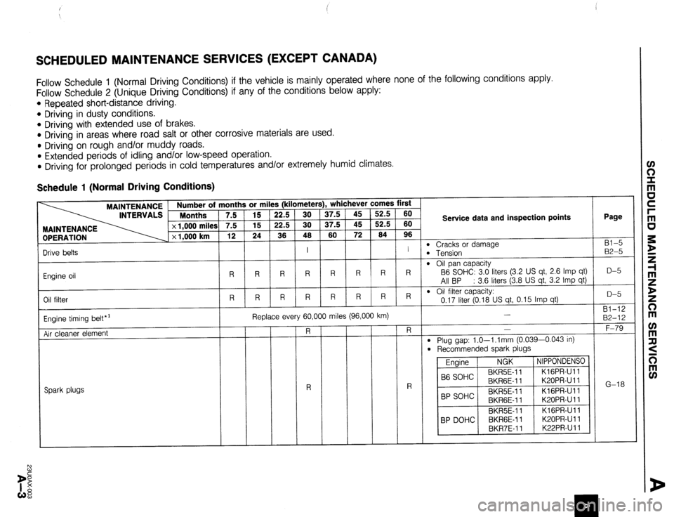
SCHEDULED MAINTENANCE SERVICES (EXCEPT CANADA)
Follow Schedule 1 (Normal Driving Conditions) if the vehicle is mainly operated where none of the following conditions apply.
Follow Schedule 2 (Unique Driving Conditions) if any of the conditions below apply:
l Repeated short-distance driving.
l Driving in dusty conditions.
* Driving with extended use of brakes.
* Driving in areas where road salt or other corrosive materials are used.
l Driving on rough and/or muddy roads.
l Extended periods of idling and/or low-speed operation.
l Driving for prolonged periods in cold temperatures and/or extremely humid climates.
Schedule 1 (Normal Driving Conditions)
Number of months or miles (kilometers), whichever comes first
Months 7.5 15 22.5 30 37.5 45 52.5 60
7.5 15 22.5 30 37.5 45 52.5 60
12 24 36 46 60 72 64 96 Service data and inspection points Page
Bl-5
B2-5
D-5
D-5
Bl-12
B2-12
F-79
G-18 MAINTENANCE
OPERATION
m Cracks or damage
B Tension
m Oil pan capacity
B6 SOHC: 3.0 liters (3.2 US qt, 2.6 Imp qt)
All BP : 3.6 liters (3.8 US qt, 3.2 Imp qt)
l Oil filter capacity:
0.17 liter (0.18 US qt, 0.15 Imp qt)
-
l Plug gap: 1.0-l .l mm (0.039-0.043 in)
l Recommended spark plugs
Engine NGK NIPPONDENSO
B6 SOHC BKR5E-11 KIGPR-Ull
BKRGE-11 K20PR-U 11
BP SOHC BKR5E-11 KlGPR-Ull
BKRGE-11 K20PR-U 11
BKR5E-11 KlGPR-Ull
BP DOHC BKRGE-11 K20PR-U 11
BKR7E-11 K22PR-Ull I I
R R R R R R R R
R R R R R R R R Drive belts
Engine oil
Oil filter
Engine timing belt*’
Air cleaner element Replace every 60,000 miles (96,000 km)
I
Spark plugs
Page 22 of 1164
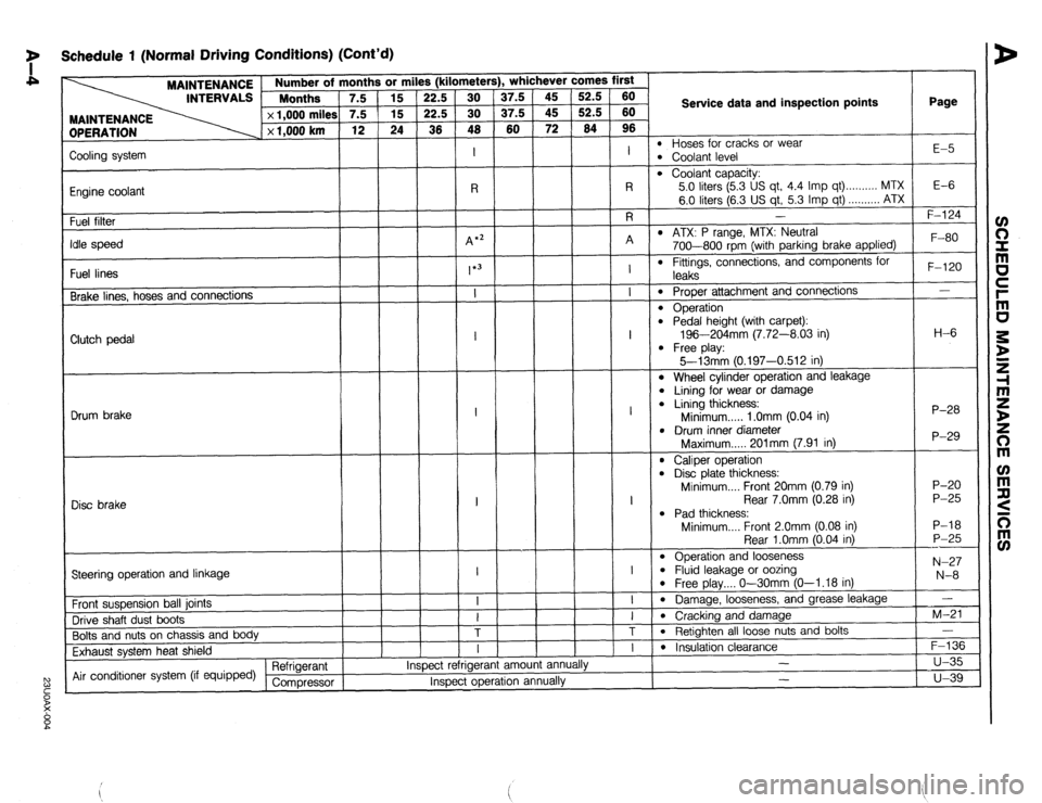
7 Schedule 1 (Normal Driving Conditions) (Cont’d)
MAINTENANCE
INTERVALS 1 ::::“’ rths ’ 7.5
DPERATION x 1,000 miles
x 1,000 km 3r mi
15
15
24
1
Page
l- . whichever comes first s (kilometer!
37.5
37.5
60 52.5
52.5
64 60
60
96
I
l-7
Service data and inspection points
l Hoses for cracks or wear l Coolant level E-5
Zooling system
Engine coolant
Fuel filter
‘die speed
Fuel lines
Brake lines, hoses and connections
l Coolant capacity:
5.0 liters (5.3 US qt, 4.4 Imp qt) . . . . . . . . . . MTX
6.0 liters (6.3 US qt, 5.3 Imp qt) . . . . . . . . . . ATX
I E-6 -
F-l 24
l ATX: P range, MTX: Neutral
700-800 rpm (with parking brake applied)
l Fittings, connections, and components for F-80
F-120
-
H-6
P-28
P-29
P-20
P-25
P-18
P-25
---
N-27
N-8
-
M-21
-
F-136
u-35
u-39 leaks
0 Proper attachment and connections
l Operation l Pedal height (with carpet):
196-204mm (7.72-8.03 in)
l Free play:
5--13mm 10.197-0.512 in) Clutch pedal
l Wheel cylinder operation and leakage
l Lining for wear or damage l Lining thickness:
Minimum . . . . . 1 .Omm (0.04 in)
l Drum inner diameter
Maximum..... 201mm (7.91 in) Drum brake
l Caliper operation l Disc plate thickness:
Minimum.... Front 20mm (0.79 in)
Rear 7.0mm (0.28 in)
l Pad thickness:
Minimum.... Front 2.0mm (0.08 in)
Rear l.Omm (0.04 in)
l Operation and looseness l Fluid leakage or oozing l Free play.... O-30mm (O-l .18 in)
l Damage, looseness, and grease leakage
l Cracking and damage
l Retighten all loose nuts and bolts I
1
Disc brake
I
---l-T
Steering operation and linkage
Front suspension ball joints
Drive shaft dust boots
Bolts and nuts on chassis and body
Exhaust system heat shield
Air conditioner system (if equipped) Refrigerant
Compressor am01 anni I
l Insulation clearance
- ,.
Inspect rerrlgerar
Inspect operation annually -
Page 24 of 1164
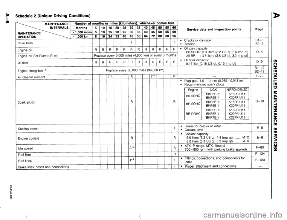
y Schedule 2 (Unique Driving Conditions)
OPERATION
Drive belts MAINTENANCE / Number of months or miles (kilometers), whichever comes first
INTERVALS Months
5 IO 15 20 25 30 35 40 45 50 55 60
x 1,000 milea i 5 10 15 20 25 30 35 40 45 50 55 60
x 1,000 km 8 16 24 32 40 48 56 64 72
80 88 96
I I Service data and inspection points Page
l Cracks or damage Bl-5 l Tension B2-5
l Oil pan capacity
B6 SOHC: 3.0 liters (3.2 US qt, 2.6 Imp qt)
All BP : 3.6 liters (3.8 US qt, 3.2 Imp qt)
l Oil filter capacity: D-5
I I I I I I I I I I I
RRRRRRR R R R R R
Replace every 3,000 miles (4,800 km) or every 3 months
R R R R R RRRRRRR
0.17 liter (0.18 US qt, 0.15 Imp qt) Engine oil
Engine oil (For Puer-to-Rico)
Oil filter D-5
81-12
82-12
F-79
G-18 Replace every 60,000 miles (96,000 km)
Engine timing belt*’
Air cleaner element -
-
-
-
-
-
-
-
- -
-
-
-
-
-
-
-
-
FL
-
R
-
I
-
R
-
4 *;
-
-
*3
T
- -
-
-
-
-
-
-
-
- -
-
-
-
-
-
-
-
-
*2 -
-
-
-
-
-
-
-
- - R -
l Plug gap: l.O--l.lmm (0.039-0.043 in)
l Recommended spark plugs
Engine NGK NIPPONDENSO
B6 SOHC BKR5E-11
KlGPR-Ull
BKRGE-I 1 K20PR-U 11
BP SOHC BKR5E-I 1 KlGPR-Ull
BKRGE-11 K20PR-U 11
BKRSE-I 1 Kl GPR-Ul 1
BP DOHC BKRGE-11 K20PRUll
BKR7E-11 K22PR-U 11 R
Spark plugs
I
l Hoses for cracks or wear l Coolant level E-5
Cooling system
R
l Coolant capacity:
5.0 liters (5.3 US qt, 4.4 Imp qt) MTX
6.0 liters (6.3 US qt, 5.3 Imp qt) ...,,,,,. ATX
l ATX: P range, MTX: Neutral E-6
Engine coolant
A
-
R
-
I
-
I Idle speed , F-80
F-124 / 700-800 rbrn (with parkina brake applied) -
- -
- , , I .I
-
Fuel filter
l Fittings, connections, and components for
leaks
l Prooer attachment and connections F-120
- Fuel lines
Brake lines. hoses and connections
Page 27 of 1164
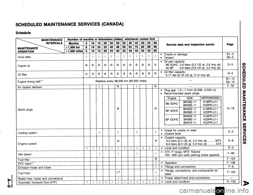
SCHEDULED MAINTENANCE SERVICES (CANADA)
Schedule
2 1,000 km
x 1,000 mile! Number of months or kilometers (miles), whichever comes first
Months 5 10 15 20 25 30 35 40 45 50 55 60
8 16 24
32 40 40 56 64 72 80 88 96
s 5 10 15 20 25 30 35 40 45 50 55 60
I I I Service data and inspection points Page
MAINTENANCE
OPERATION
l Cracks or damage Bl-5 l Tension 82-5
l Oil pan capacity
B6 SOHC: 3.0 liters (3.2 US qt, 2.6 Imp qt)
All BP : 3.6 liters (3.8 US qt, 3.2 Imp qt)
l Oil filter capacity: D-5
0.17 liter (0.18 US qt, 0.15 Imp qt) Drive belts I I I I I I I I I I I I
Engine oil RRRRRRR R R R R R
Oil filter R R R R R R R R R R R R D-5
81-12
82-12
F-79 Replace every 96,000 km (60,000 miles)
Engine timing belt*’
Air cleaner element
T
-
-
I
-
-i
-
I
-
-
-
-
-
-i-
- -
R -
-
-
-
T
-
-
-
-
-
-
-7
- -
-
-
-
T
-
-
-
-
-
-
T
- -r
-
-
I
-
T
-
I
-
-
-
-
-
-i
-
-
-
-
-
T
-
-
-
-
-
-
T
- -
-
-
-
T
-
-
-
-
-
-
T
- i?-
-
R
-
I
-
R
-i
-
I
F
T
T
-
I
-i
-i
-
-
-
-
-
T
-
-
-
-
-
-
-i
- -
l Plug gap: 1.0-l .l mm (0.039-0.043 in)
l Recommended spark plugs .-
Engine NGK NIPPONDENSO
86 SOHC BKR5E-11 KlGPR-Ull
BKRGE-11 K20PR-U 11
BP SOHC BKR5E-11 KlGPR-Ull
BKRGE-11 K20PR-U
11
BKRSE-11 KlGPR-Ull
BP DOHC BKRGE-11 K20PR-U 11
BKR7E-11 K22PRU 11 G-18
R
-
I
-
R
-i- Spark plugs -
-
-
-
I
-
-
E-5
Cooling system l Hoses for cracks or wear
l Coolant level
0 Coolant capacity: 5.0
liters (5.3 US qt, 4.4 imp qt) ..,.,..,,. MTX
6.0 liters (6.3 US qt, 5.3 Imp qt) . . . . . . . . . . ATX
l Level and condition
l ATX: P range, MTX: Neutral
700-800 rpm (with parking brake applied) E-6
Engine coolant
E-5
F-80
F-124 I
- I
Idle speed
Fuel filter
PCV valve *’
Emission hoses and tubes
Fuel lines
Brake lines, hoses and connections
Automatic transaxle fluid (ATF) -
-
-
I *2
l Operation - F-138
F-6 -
-
- -
-
-
l Fittings and connections
l Fittings, connections, and components for
leaks
l Proper attachment and connections
l Level and conditinn F-l 20 - K-l 35
I I
- I
- I
Page 239 of 1164

OUTLINE, TROUBLESHOOTING GUIDE D
OUTLINE
SPECIFICATIONS
Engine
Item
--
Lubrication system
Type
011 pump
Relief pressure kPa (kg/cm2, psi)
_~__
Type Oil filter
Relief pressure differential kPa (kg/cm2, psi)
Oil pressure switch activation pressure
kPa (kg/cm’, psi)
Total (dry engine)
liters (US qt, Imp qt)
Oil capacity Oil pan liters (US qt, Imp qt)
Oil filter liter (US qt, Imp qt)
Engine oil
Above -25OC (-13’F)
Viscosity number
Below 0% (32OF) BP SOHC BP DOHC
B6 SOHC
Force-fed type
Trochoid gear
343-441 (3.5-4.5, 50-64) m I, Full-flow, paper element
78-l 18 (0.8-l .2, 1 l-i 7)
25 (0.25, 3.6)
3.4 (3.6, 3.0) 4.0 (4.2, 3.5)
3.0 (3.2, 2.6) 3.6 (3.8, 3.2)
0.17 (0.18, 0.15)
API service SG Energy ConservingII (ECII) Only
SAE low-30
SAE 5W-30
23UODX-005
TROUBLESHOOTING GUIDE
Problem
Engine hard starting
Excessive oil
consumption
Oil pressure drop
Warming lamp
illuminates while
engine is running Possible Cause
Improper engine oil
Insufficient engine oil
Oil working up or down
011 leakage
Insufficient oil
Oil leakage
Worn and/or damaged oil pump gear
Worn plunger (inside oil pump) or weak spring
Clogged oil strainer
Excessive main bearing or connecting rod bearing
clearance
Oil pressure drop
Malfunction of oil pressure switch
Malfunction of electrical system Remedy
Replace
Add oil
Refer to Section B
Repair
Add oil
Repair
Replace
Replace
Clean
Refer to Section B
As described above
Refer to Section T
Refer to Section T Page
D- 7
D- 7
-
D- 7
-
D-13, 14
D-13, 14
-
-
23UODX-015
D-5
Page 267 of 1164
F
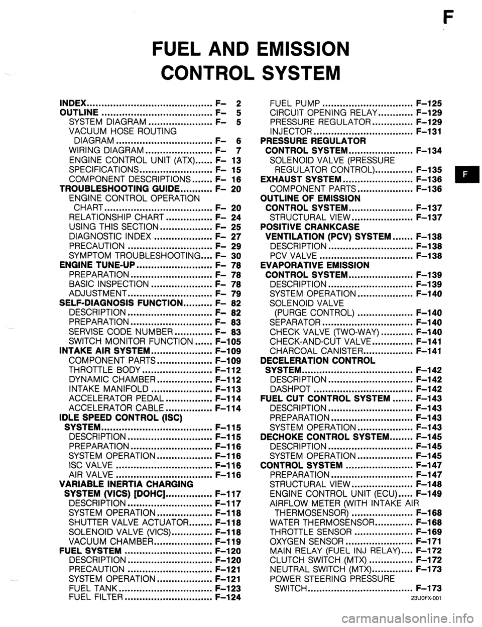
FUEL AND EMISSION
CONTROL SYSTEM
INDEX ...........................................
OUTLINE ...................................... ;: 2
SYSTEM DIAGRAM ...................... F-
:
VACUUM HOSE ROUTING
DIAGRAM .................................
WIRING DIAGRAM ....................... F- 6
- 7
ENGINE CONTROL UNIT (ATX) ...... F- 13
SPECIFICATIONS.. ....................... F- 15
COMPONENT DESCRIPTIONS.
...... F- 16
TROUBLESHOOTING GUIDE.. ......... F- 20
ENGINE CONTROL OPERATION
CHART
..................................... F- 20
RELATIONSHIP CHART.. .............. F- 24
USING THIS SECTION .................. F- 25
DIAGNOSTIC INDEX .................... F- 27
PRECAUTION ............................. F- 29
SYMPTOM TROUBLESHOOTING .... F- 30
ENGINE TUNE-UP
.......................... F- 76
PREPARATION ............................
F- 76
BASIC INSPECTION ..................... F- 78
ADJUSTMENT .............................
F- 79
SELF-DIAGNOSIS FUNCTION .......... F- 82
DESCRIPTION .............................
F- 82
PREPARATION
............................
F- 83
SERVISE CODE NUMBER.. ........... F- 83
SWITCH MONITOR FUNCTION ...... F-105
INTAKE AIR SYSTEM.. ................... F-109
COMPONENT PARTS.. ................. F-109
THROTTLE BODY ........................ F-l 12
DYNAMIC CHAMBER ................... F-l 12
INTAKE MANIFOLD ..................... F-l 13
ACCELERATOR PEDAL ................ F-l 14
ACCELERATOR CABLE ................ F-l 14
IDLE SPEED CONTROL (ISC)
SYSTEM ......................................
F-115
DESCRIPTION ............................. F-115
PREPARATION
............................ F-116
SYSTEM OPERATION.. ................. F-l 16
ISC VALVE ................................. F-116
AIR VALVE
................................. F-116
VARIABLE INERTIA CHARGING
SYSTEM (VICS) [DOHC] ................ F-l 17
DESCRIPTION ............................. F-117
SYSTEM OPERATION ................... F-l 18
SHUTTER VALVE ACTUATOR.. ...... F-l 18
SOLENOID VALVE (VICS). ............. F-118
VACUUM CHAMBER.. .................. F-119
FUELSYSTEM .............................. F-l 20
DESCRIPTION
............................. F-l 20
PRECAUTION ............................. F-121
SYSTEM OPERATION.. ................. F-121
FUEL TANK ................................
F-l 23
FUEL FILTER .............................. F-l 24 FUEL PUMP ............................... F-l 25
CIRCUIT OPENING RELAY.. .......... F-129
PRESSURE REGULATOR.. ............ F-129
INJECTOR .................................. F-l 31
PRESSURE REGULATOR
CONTROL SYSTEM.. .................... F-l 34
SOLENOID VALVE (PRESSURE
REGULATOR CONTROL). ............ F-l 35
EXHAUST SYSTEM ........................ F-l 36
COMPONENT PARTS.. ................. F-136
OUTLINE OF EMISSION
CONTROL SYSTEM.. .................... F-l 37
STRUCTURAL VIEW.. ................... F-l 37
POSITIVE CRANKCASE
VENTILATION (PCV) SYSTEM.. ..... F-138
DESCRIPTION .............................
F-l 38
PCV VALVE ................................ F-l 38
EVAPORATIVE EMISSION
CONTROL SYSTEM.. .................... F-l 39
DESCRIPTION ............................. F-l 39
SYSTEM OPERATION.. ................. F-140
SOLENOID VALVE
(PURGE CONTROL) ................... F-140
SEPARATOR ............................... F-l 40
CHECK VALVE (TWO-WAY) ........... F-140
CHECK-AND-CUT VALVE.. ............ F-141
CHARCOAL CANISTER.. ............... F-141
DECELERATION CONTROL
SYSTEM ...................................... F-l 42
DESCRIPTION ............................. F-l 42
DASHPOT .................................. F-142
FUEL CUT CONTROL SYSTEM ....... F-143
DESCRIPTION ............................. F-l 43
PREPARATION ............................ F-l 43
SYSTEM OPERATION.. ................. F-143
DECHOKE CONTROL SYSTEM.. ...... F-145
DESCRIPTION ............................. F-l 45
SYSTEM OPERATION ................... F-l 45
CONTROL SYSTEM ....................... F-l 47
PREPARATION ............................ F-147
STRUCTURAL VIEW.. ................... F-l 48
ENGINE CONTROL UNIT (ECU) ..... F-149
AIRFLOW METER (WITH INTAKE AIR
THERMOSENSOR) ..................... F-168
WATER THERMOSENSOR.. ........... F-168
THROTTLE SENSOR .................... F-l 69
OXYGEN SENSOR.. ..................... F-171
MAIN RELAY (FUEL INJ RELAY) .... F-172
CLUTCH SWITCH (MTX) ............... F-172
NEUTRAL SWITCH (MTX). ............. F-173
POWER STEERING PRESSURE
SWITCH .................................... F-173
WJOFX-001
Page 269 of 1164

INDEX F
1. Resonance duct
Inspection / Replacement.. ........ page F-l 09
2. Air cleaner element
Inspection ................................. page F- 79
Replacement.. ........................... page F-l 09
3. Airflow meter
(With intake air thermosensor)
Inspection
................................. page F-l 68
Replacement.. ........................... page F-l 09
4. Resonance chamber
Inspection I Replacement.. ........ page F-l 09
5. Throttle body
Inspection .................................
page F-l 12
Replacement.. ...........................
page F-l 09
6. Throttle sensor
inspection ................................. page F-l 69
Adjustment..
.............................. page F-l 69
Replacement.. ........................... page F-l 71
7. ISC valve
Inspection ................................. page F-l 16
Replacement..
........................... page F-l 09
8. Dashpot
Inspection ................................. page F-l 42
9. Dynamic chamber
Removal / Installation ................
page F-109
Inspection [DOHC] ................... page F-l 12
10. Air valve
Inspection
................................. page F-l 16
Removal / Installation ................ page F-109
11. Shutter valve actuator
Inspection ................................. page F-l 18
12. Vacuum chamber [DOHC]
Inspection ................................. page F-l 19
13. Intake manifold
Removal / Installation ................ page F-l 09
14. Injector
Inspection .................................
page F-l 31
Removal .................................... page F-131
Installation.. ............................... page F-l 33 15. Pressure regulator
Inspection ................................. page F-l 29
Replacement ............................. page F-l 30
16. Solenoid valve (Pressure regulator control)
[BP1
Inspection ................................. page F-l 35
17. Solenoid valve (VICS) [DOHC]
Inspection ................................. page F-l 18
18. Charcoal canister
Inspection ................................. page F-l 41
19. Solenoid valve (Purge control)
Inspection ................................. page F-l 40
20. Circuit opening relay
Inspection ................................. page F-l 29
Replacement ............................. page F-l 29
21. Engine control unit (ECU)
Removal / Installation ................ page F-l 49
Inspection ................................. page F-149
22. Clutch switch (MTX)
Inspection ................................. page F-l 72
Replacement.. ........................... page F-l 72
23. PCV valve
Inspection ................................. page F-l 38
24. Water thermosensor
Removal / Inspection /
Installation ............................... page F-l 68
25. Fuel filter (High-pressure side)
Replacement.. ........................... page F-l 24
26. Main relay (FUEL INJ relay)
Inspection ................................. page F-l 72
27. Neutral switch (MTX)
inspection ................................. page F-l 73
Replacement.. ........................... page F-l 73
28. Oxygen sensor
Inspection ................................. page F-l 71
Replacement ............................. page F-l 72
29. Power steering pressure switch
Inspection ................................. page F-l 73
Replacement.. ........................... page F-l 73
23UOFX-002
F-3
Page 271 of 1164
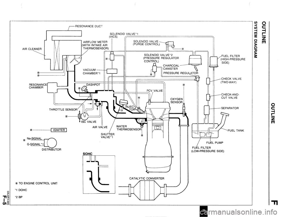
RESONANCE DUCT
SOLENOID VALVE’1
AIR CLEANER
ix
%
4.L VACUUM
CHAMBER-1
RESONANCE
CHAMBER DASHPOT
w/r) --CHECK VALVE
(TWO-WAY)
I II 14 J--CHECK-AND-
II l/%x II/ II _ \,\, _.-.,I CUT VALVE
TH
?z% ---{ IGNITER 1
~ Ne-SIGNAL 1/
G-SIGNAL’IU
DISTRIBUTOR AIR VA’LVE
/ WATER
THERMOSENSOR
SHUTTER 7
VALVE * 1 s%
SOHC
% TO ENGINE CONTROL UNIT
‘1 DOHC
‘2 BP
I CATALYTIC CONVERTER /
FU’EL PUMP
FUEL FILTER
(LOW-PRESSURE SIDE)
Page 281 of 1164
OUTLINE F
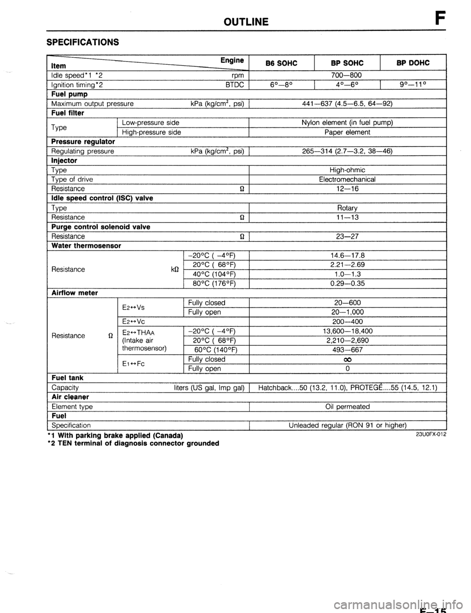
SPECIFICATIONS
Item
Idle speed*1 *2
Ignition timing*2
Fuel pump
Maximum outout Dressure Engine
rpm B6 SOHC
6O--80 BTDC 1
kPa (ka/cm’. osi1 1 BP SOHC
700-800
4O---6O BP DOHC
90-l 1 O
441-637 (4.5-6.5. 64-92) I
I Fuel filter I
Type Low-pressure side Nylon element (in fuel pump)
High-pressure side Paper element
Pressure reaulator
Regulating pressure kPa (kg/cm’, psi) 1 265-314 (2.7-3.2, 38-46)
I lniector I
Type Type of drive
Resistance
Idle speed control (ISC) valve
TvDe , ,
t Resistance
Purge control solenoid valve
Resistance
Water thermosensor n High-ohmic
Electromechanical
12-16
Rotarv
n I II-13 I
n 1 23-27
1 -20% I -4OFj 1 14.6-17.8
Resistance k62 2ooc i 68OF) 2.21-2.69
40°C (104OF) 1.0-l .3
80°C (176OF) 0.29-0.35
Airflow meter
E2++Vs
E2-Vc Fully closed
Fully open 20-600
20-l ,000
200-400
Capacity liters (US gal, Imp gal) 1 Hatchback 50 (13.2, ll.O), PROTEGE ,... 55 (14.5, 12.1)
I Air cleaner I
Element type
Fuel
Specification l
l Wlth parking brake applied (Canada)
‘2 TEN terminal of diagnosis connector grounded Oil permeated
Unleaded regular (RON 91 or higher) 23UOFX-012
F-l 5
Page 282 of 1164
F OUTLINE
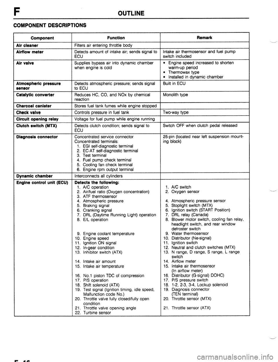
COMPONENT DESCRIPTIONS
Component
Air cleaner
Airflow meter
Mr valve
Atmospheric pressure
Sensor
Catalytic converter Function Remark
Filters air entering throttle body
Detects amount of intake air; sends signal to intake air thermosensor and fuel pump
ECU switch included
Supplies bypass air into dynamic chamber
l Engine speed increased to shorten
when engine is cold warm-up period
l Thermowax type l Installed in dynamic chamber
Detects atmospheric pressure; sends signal Built in ECU
to ECU
Reduces HC, CO, and NOx by chemical Monolith type
reaction Charcoal canister
Stores fuel tank fumes while engine stopped Check valve
Controls pressure in fuel tank Two-way type Circuit opening relay
Voltage for fuel pump while engine running Clutch switch (MTX)
Detects clutch condition; sends signal to Switch OFF when clutch pedal released
ECU Diagnosis connector
Concentrated service connector 25pin (located near left suspension mount-
Concentrated terminals: ing block)
1. EGI self-diagnostic terminal
2. EC-AT self-diagnostic terminal
3. Test terminal
4. Fuel pump check terminal
5. Cooling fan check terminal
6. Engine rpm output terminal Dynamic chamber
Interconnects all cylinders Engine control unit (ECU) Detects the following:
1. A/C operation 1. A/C switch
2. Air/fuel ratio (Oxygen concentration) 2. Oxygen sensor
3. ATF thermosensor
4. Atmospheric pressure 4. Atmospheric pressure sensor
5. Braking signal 5. Stoplight switch (MTX)
6. Cranking signal 6. Ignition switch (START Position)
7. DRL (Daytime Running Light) operation 7. DRL relay (Canada)
8. E/L operation 8. Blower motor switch, cooling fan relay,
headlight switch, and rear window
defroster switch
9. Engine coolant temperature 9. Water thermosensor
10. Engine speed 10. Distributor (Ne-signal)
11. Ignition ON signal 11. Ignition switch
12. In-gear condition 12. Neutral and clutch switches (MTX)
13. Inhibitor switch (ATX) 13. N range, D range, S range, L range
switch
14. Intake air amount 14. Airflow meter
15. Intake air temperature 15. Intake air thermosensor
(In airflow meter)
16. No.1 piston TDC of compression
17. P/S operation
18. Shift solenoid (ATX)
19. Test signal (Ignition timing, idle speed,
Malfunction code No.)
20. Throttle valve fully closed/fully open
condition 16. Distributor (G-signal) DOHC)
17. P/S pressure switch
18. 1-2, 2-3, 3-4, Lockup solenoid
19. Diagnosis connector
(TEN terminal)
20. Throttle sensor (MTX)
21. Throttle valve opening angle
22. Turbine sensor 21. Throttle sensor (ATX) .__r
F-10