reset MAZDA PROTEGE 1992 Workshop Manual
[x] Cancel search | Manufacturer: MAZDA, Model Year: 1992, Model line: PROTEGE, Model: MAZDA PROTEGE 1992Pages: 1164, PDF Size: 81.9 MB
Page 426 of 1164

CONTROL SYSTEM
VB: Battery voltage
erminal Input Output
Connection to Test condition Correct voltage
Remark
1L
0 A/C relay Ignition switch ON VB
A/C switch ON at idle Below 2.5V
A/C switch OFF at idle V0
-
1M 0
1N 0 Vehicle speed
sensor
P/S pressure
switch While driving 4--5v
Vehicle stopped 0 or 8V
Ignition switch ON
VB
P/S ON at idle
ov
P/S OFF at idle Vi3 -
-
10 0 A/C switch A/C switch ON
A/C switch OFF Below 2.5V ignition switch
VB ON and blower
motor ON
IP 0 Blower control
switch Blower control switch OFF or 1st position Ve ignition switch
Blower control switch 2nd or higher po- Below 1 .OV ON
sition
1Q 0
1R 0
1s 0
IT 0 Stoplight switch Brake pedal released Below 1 .OV
-
Brake pedal depressed VI3
Inhibitor switch N or P range ov Ignition switch
(P, N ranges) ON
Other range VI3
Cruise control main Normal condition
VB Ignition switch
switch ON
Set or Resume switch ON or vehicle speed Below 1 .OV
8 km/h (5 mph) lower than preset speed
(Driving vehicle cruise control operation)
Throttle sensor Accelerator pedal released Below 1 .OV Ignition switch
(Idle switch)
Accelerator pedal depressed V0 ON
1u - - -
- - -
1v - - - -
- -
2A 0 Distributor Ignition switch ON Approx. OV
(Ne-signal) or 5V -
Idle Approx. 2V
LY”“l I. A3 311 blFY.1.
J
- .*
F-160
Page 870 of 1164

T FUSE AND JOINT BOX
Specifications (Cont’d)
Fuse Color
METER 15A Blue
WIPER 20A Yellow
STOP 20A Yellow
TAIL 15A
Blue
SUNROOF 15A Blue
DEFOG 20A Yellow
HEATER 30A Light green Protected circuit Instrument panel (gauges and warning lamps), Back-up light, Turn signal,
Cruise control system
Windshield wiper and washer
Stoplight, Horn
Taillight, Side marker light, Parking light, Illumination light, License plate light
Sunroof
Rear window defroster
Blower motor
13UOTX-067
L
r 03UOTX-01
1 BL
PULLER
t
L 03UOTX-01
CIRCUIT
BREAKER
RESET BUTTON
03UOTX.01
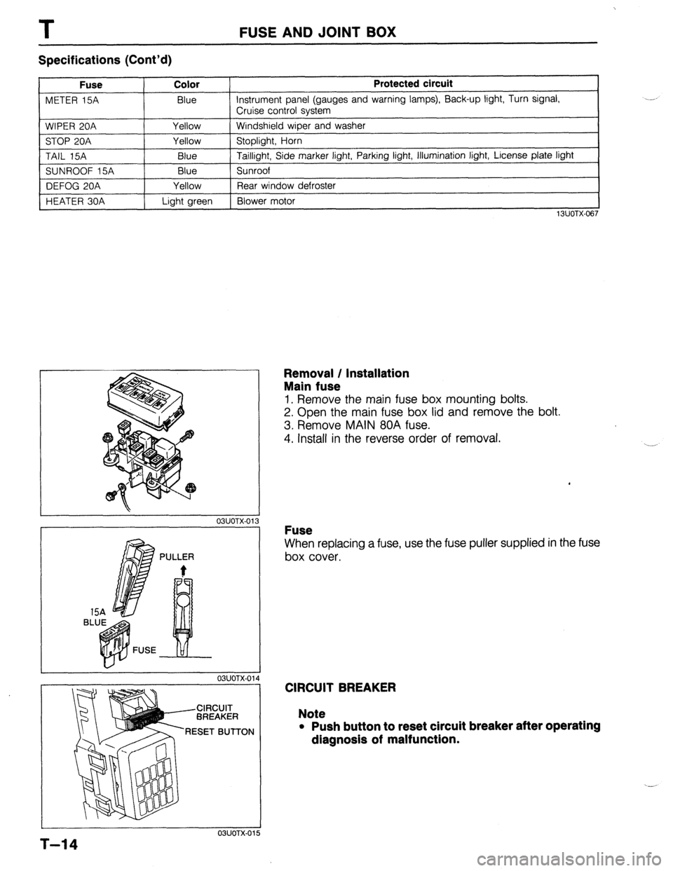
Removal / Installation
Main fuse
1. Remove the main fuse box mounting bolts.
2. Open the main fuse box lid and remove the bolt.
3. Remove MAIN 80A fuse.
4. Install in the reverse order of removal.
Fuse
When replacing a fuse, use the fuse puller supplied in the fuse
box cover.
CIRCUIT BREAKER
Note
l Push button to reset circuit breaker after operating
dlagnosls of malfunction.
5
T-14
Page 962 of 1164

U TROUBLESHOOTING GUIDE
Symptom: Blower motor does not operate.
Normal operation of blower motor
Blower motor speed is controlled by the blower switch and a resistor assembly in the blower unit.
When the blower switch is in the OFF position, the motor ground circuit is open and the blower motor does
not operate. When the switch is in the first (Low) position, current flow from the blower motor is restricted
by the three resistors in the resistor assembly, and the blower motor turns at low speed.
Changing the blower switch to the second (Mid), third (High), or fourth (Super-high) positions causes the
circuit resistance to decrease, and the blower motor speed to become correspondingly faster.
03uoux-005
. HEATER 30A
CIRCUIT
BREAKER
RED BUTTON
23UOUX-01
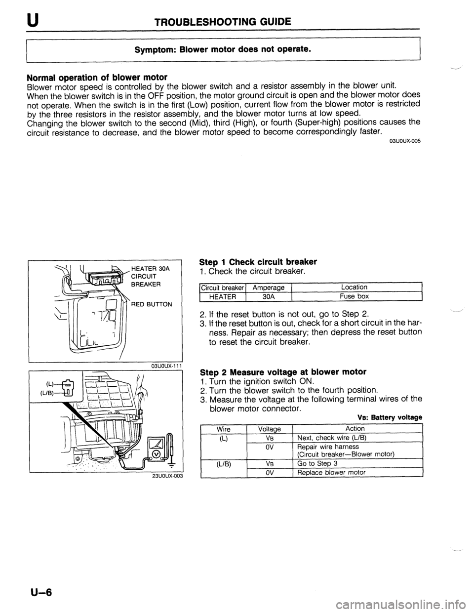
Step 1 Check circuit breaker
1. Check the circuit breaker.
ircuit breaker] Amperage ( Location
HEATER 1 30A Fuse box
2. If the reset button is not out, go to Step 2.
3. If the reset button is out, check for a short circuit in the har-
ness. Repair as necessary; then depress the reset button
to reset the circuit breaker.
Step 2 Measure voltage at blower motor
1. Turn the ignition switch ON.
2. Turn the blower switch to the fourth position.
3. Measure the voltage at the following terminal wires of the
blower motor connector.
VB: Battery voltage
Wire
Voltage Action
a-) VB Next, check wire (L/B)
ov ReDair wire harness
(Ciicuit breaker-Blower motor)
U-W VB Go to Step 3
ov Replace blower motor
U-6
Page 1096 of 1164

Terminal vdt
wminal lrput
1A -
1B 0
-
1C 0
1D e (ATX) ve: aattefy voltage
1
Connected to
I Test wndition ~cwrect rc4t.gej F&W*
-
0
-
-
3attery
Uain r&y
:FUEL INJ relay) Constant
tgnition swdch V% For backt@
OFF ov
ON V6
Ignition swtch
(START)
Self-Diagnosis
Checker
[monitor lamp)
3 - White crankii npprox 1ov
fgnition switch ON ov
Test swtch at “SELF-TEST’ With Self-
Lamp illuminated for 3 sec. after igmtmn 4.5-5.w Diagnosis Check-
switch OFF-+ON er and System
Selector
Lamp net illuminated after 3 Sec. VS
Test swtch at “02 MONITOR” at idle
i Monitor lamp illuminated 4.5-55v
Test switch at “02 MONtTOR” at idfe
Monitor lamp not illuminated
Malfunction indicator
lamp illuminated for 3 sec. after ignition
Below 2 5v With System
lalllp switch OFF+ON selector test
WLI switch at
Lamp not luminated after 3 sec. VE
“SELF-TEST”
lamp ifluminated BelOW 2.w
Lamp not illuminated VS
Self-Diagnosis Buzzer sounded for 3 sec. after ignrtion
l With Self-
Checker switch OFF-+ON Below 2.5V
Diagm!3s
(code number) Checker and
Buzzer not sounded after 3 set VB
system
Select0 Buzzer sou&?d Below 2 5v l With System
Selector test
I Buzzer not sounded
tgmter Ignition switch ON ov
Idle Appror 0 2v -
Headlight switch Headlights ON
f VB
-
Headlbhts OFF ! ov
Diagnosis
connector
, System Selector test switch at
VS Ignition witch
“02 MONITOR” ON
(TEN terminal)
Rear window
defroster switch
Ground Icalifornia) System Selector tesf switch at
“SELF-TEST”
Rear window defroster watch OFF
Rear window de!roster watch ON
ConSlant QV
ov lgmhon switch
__ ON
VO
ov
- Main relay (canadal fgmtion switch ON VB
AC relay Ignitiin switch ON VB
A/C switch ON at Idle Below 2.5% -
Vehicle speed A/C switch OFF at Gle
/ Vehicle stopped
P/S pressure
switch lgmhon switch ON
P/S ON at idle Iturnino)
I.
P/S OFF at idle I VB Terminal voltage v‘s: Battery vottage
I I
1
Terminal input Output Connected to Test condition comcl voltage Remark
10
0 A/C swatch AIC switch ON Befow25V ignition switch
ON and blower
A/C switch OFF VB I
motor ON
IP
ii Blower control Blower control swtch OFF or 1 St poSItion VB tgnibon switch
switch ON
Blower control switch 2nd or higher
ov
position
1Q
0 Stopltght switch Brake pedal released Below 1 ov
-
IT <; Brake pedal depressed VE
lnhtbitor switch N or P range ov Ignition switch
(P N range) ON
Other ranges VB
Cruise control man Set or Resume swtch ON or vehicle speed lgmhon swtch
switch 8kmih &mph) lower than preset speed &tow 1 5~ ON
(Drwng vehcfe crwse cantrol
OperatiOn)
Fk
z 1v -
3A ’ Throttle Sensor
(Idle switch) Normal conditions
Accelerator pedal released
Accelerator pedal depressed “8
Bebw 1 ov lgnihon swatch
ON
VS
I -
-
- - -
-
-
- - -
D&rib&r
-‘. / b / / (Ne-signal) lgmtion swtch ON
/ ,,,, Approx. OV
or 5v
-
Approx 2v
I ._.
/
28 1
AdlOw meter lgmhon switch ON
Approx 3 BV .,
-
Idle Approx 3 3V
2c j r:
I \’ oxygen sensor fgmtson switch ON ov
1
20 Idle (cold englIIei
Idle (after warn-up)
lncreasma enwe speed (after warm-up) ov
O-l ov -
0 w-1 .ov
_ -
,
Deceleration o-o 4v
Coolmg fan swtch Fan operahng (engine coolant temperature
over 97°C (207’F) or diagnosis connector DV
termmat TFA grounded) -
Fan not operatmg (idle)
Water thermosensor Engine codant temperature L” %, I”” I , ‘Y”8’.“” . . . ...-1.
After warm-up
I
Thrnttb SP”SOi 1 Accelerator pedal released Approx 0.5V
2G .._..._ --..--
-
Accelerator pedal fully depressed Approx. 4 OV
0 ATF thermosensor -XPC (-2o”~)--1x1~c (302°F) aprxox as5-~m lgmhon swtch
ON
ATF temp 20°C (68°F) Approx. 4.6V
13OOC (266°F) Aporox 1.54V
I I I I I I
2H / i, I / Hold switch Hold mode Below 2V Ingbhon switch
Normal mode