check oil MAZDA PROTEGE 1992 Service Manual
[x] Cancel search | Manufacturer: MAZDA, Model Year: 1992, Model line: PROTEGE, Model: MAZDA PROTEGE 1992Pages: 1164, PDF Size: 81.9 MB
Page 340 of 1164
![MAZDA PROTEGE 1992 Service Manual F TROUBLESHOOTING GUIDE
I 24 I EXHAUST SULFUR SMELL I
DESCRIP-
l Exhaust gas smells abnormally
TION
[TROUBLESHOOTING HINTS]
High sulfur content fuel used
STEP INSPECTION
1
Change fuel to anot MAZDA PROTEGE 1992 Service Manual F TROUBLESHOOTING GUIDE
I 24 I EXHAUST SULFUR SMELL I
DESCRIP-
l Exhaust gas smells abnormally
TION
[TROUBLESHOOTING HINTS]
High sulfur content fuel used
STEP INSPECTION
1
Change fuel to anot](/img/28/57077/w960_57077-339.png)
F TROUBLESHOOTING GUIDE
I 24 I EXHAUST SULFUR SMELL I
DESCRIP-
l Exhaust gas smells abnormally
TION
[TROUBLESHOOTING HINTS]
High sulfur content fuel used
STEP INSPECTION
1
Change fuel to another brand ACTION
03UOFX-039
25 HIGH OIL CONSUMPTION
DESCRIP-
l Oil consumption excessive
TION
[TROUBLESHOOTING HINTS]
@ PCV system malfunction
@ Engine malfunction (Oil working up, working down, or leakage)
iTEP
INSPECTION
1 Check if PCV hose, ventilation hose or their at- Yes Repair or replace
taching nipples are separated, damaged,
clogged, or restricted
w page F-138 No Go to next step
2 Check if air pressure or oil is present at ventila- Yes Go to next step
tion hose ACTION
No Check engine condition w page 81-3
82-3
l Oil leakage
*Worn valve seal
*Worn valve stem
*Worn valve guide
3 Check if vacuum is felt at PCV valve at idle Yes Check engine condition w page 91-3
w page F-138 82-3
*Worn piston ring groove
*Stuck piston rings l
Worn piston or cylinder
No Replace PCV valve
23UOFX-040 /-.
F-74
Page 344 of 1164

F ENGINE TUNE-UP
ENGINE TUNE-UP
PREPARATlON
SST
I
I I
49 BO19 9AO
System Selector For
inspection of igni-
tion timing and
idle speed
hA ‘I
03UOFX-04
03UOFX-04
03UOFX-04
NG POINT
03UOFX-04 03UOFX-045
BASIC INSPECTION
Engine Oil
1. Remove the engine oil level gauge and check the engine
oil level and oil condition.
2. Add or change the oil as necessary.
Coolant
Warning
l Never remove the radiator cap while the engine is
hot.
l Wrap a thick cloth around the cap before carefully
removing it.
1. Remove the coolant level gauge from the coolant reservoir.
2. Check that the coolant level is between the L and F marks
of the gauge.
3. Add coolant if necessary.
Battery
1. Check for corrosion on the terminals and for loose cable
connections. If necessary, clean the clamps and tighten
them firmly.
2. Check that the electrolyte level is between the UPPER LEV-
EL and LOWER LEVEL marks.
3. Add distilled water if necessary.
4. Check the specific gravity with a hydrometer.
Gravity: 1.27-l .29 (at 20% [68OF] )
Page 345 of 1164

ENGINE TUNE-UP F
03UOFX.051
03UOFX-051
- w4TEN I
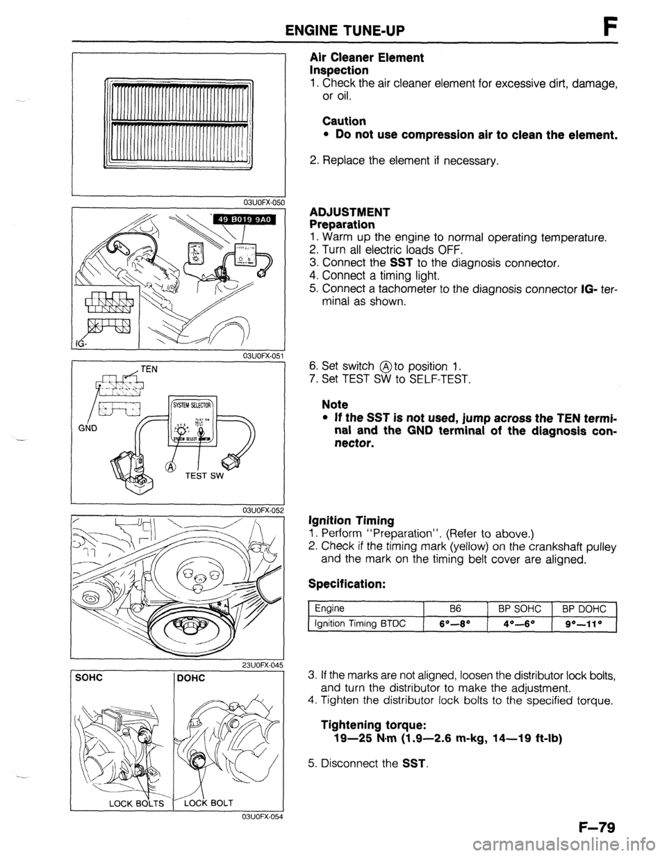
Air Cleaner Element
Inspection
1. Check the air cleaner element for excessive dirt, damage,
or oil.
Caution
l Do not use compression air to clean the element.
2. Replace the element if necessary.
ADJUSTMENT
Preparation
1. Warm up the engine to normal operating temperature.
2. Turn all electric loads OFF.
3. Connect the
SST to the diagnosis connector.
4. Connect a timing light.
5. Connect a tachometer to the diagnosis connector
IG- ter-
minal as shown.
6. Set switch @to position 1.
7. Set TEST SW to SELF-TEST.
Note
l If the SST is not used, jump across the TEN termi-
nal and the GND terminal of the diagnosis con-
nector.
Ignition Timing
1. Perform “Preparation”. (Refer to above.)
2. Check if the timing mark (yellow) on the crankshaft pulley
and the mark on the timing belt cover are aligned.
Specification:
Engine
Ignition Timing BTDC B6 BP SOHC BP DOHC
6O-8* 4O--6O go-110
SOHC DOHC
I 03UOFX-054
3. If the marks are not aligned, loosen the distributor lock bolts,
and turn the distributor to make the adjustment.
4. Tighten the distributor lock bolts to the specified torque.
Tightening torque:
19-25 N#m (1.9-2.6 m-kg, 14-19 ft-lb)
5. Disconnect the SST.
F-79
Page 394 of 1164

F FUELSYSTEM
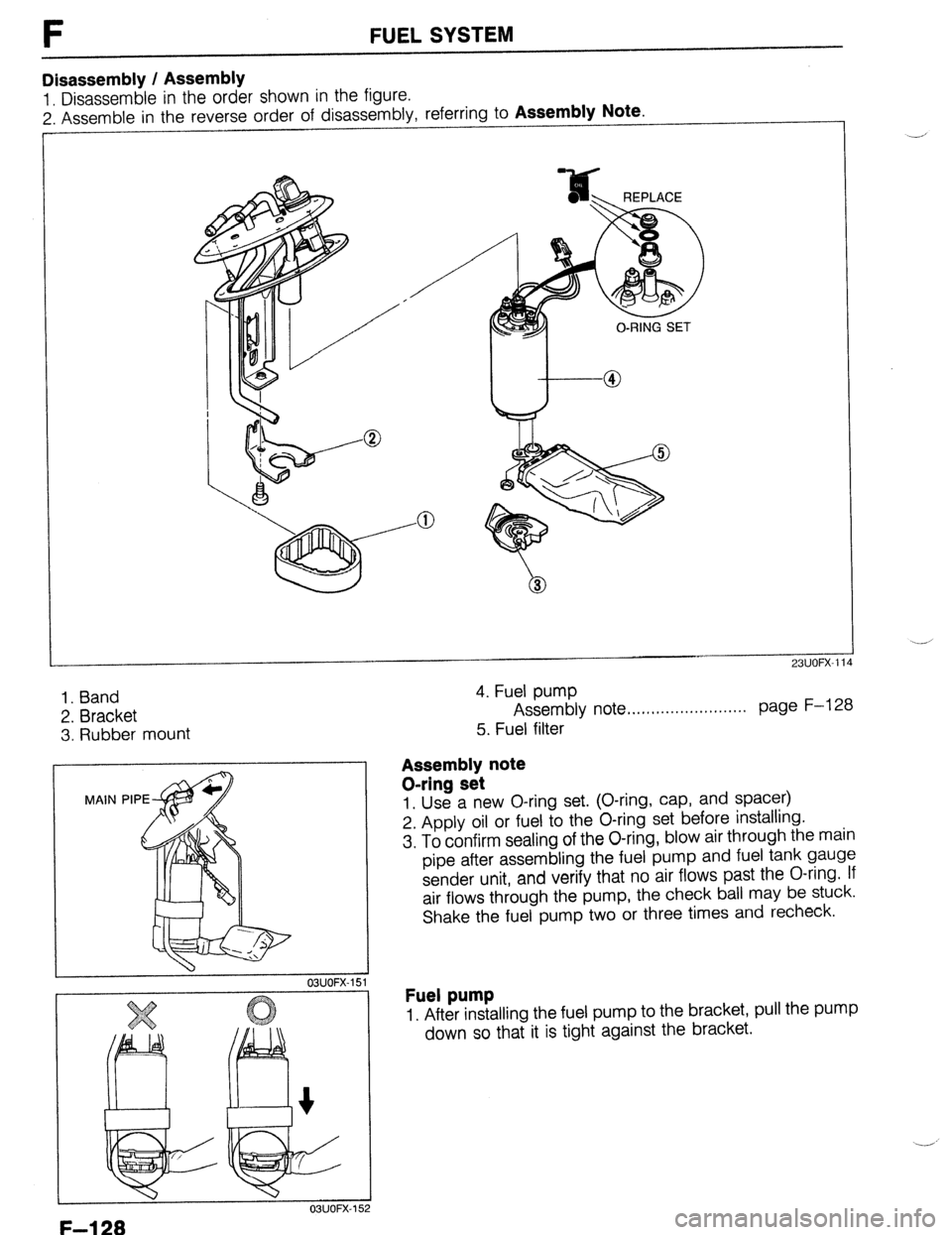
Disassembly / Assembly
1. Disassemble in the order shown in the figure.
2. Assemble in the reverse order of disassembly, referring to
Assembly Note
1. Band
2. Bracket
3. Rubber mount
OSUOFX-152
4. Fuel pump
Assembly note ,..........,....,,....,.. page F-l 28
5. Fuel filter
Assembly note
O-ring set
1. Use a new O-ring set. (O-ring, cap, and spacer)
2. Apply oil or fuel to the O-ring set before installing.
3. To confirm sealing of the O-ring, blow air through the main
pipe after assembling the fuel pump and fuel tank gauge
sender unit, and verify that no air flows past the O-ring. If
air flows through the pump, the check ball may be stuck.
Shake the fuel pump two or three times and recheck.
Fuel pump
1. After installing the fuel pump to the bracket, pull the pump
down so that it is tight against the bracket.
F-l 28
Page 444 of 1164

TROUBLESHOOTING GUIDE
TROUBLESHOOTING GUIDE
DIAGNOSTIC INDEX
No. Troubleshooting items
Page
1
Will not crank-starter motor does not operate G-4
2
Will not crank-starter motor spins G-4
3
Cranks slowly G-5 4
Alternator warning lamp illuminates when engine running
G-5
5 Discharged battery G-5
6
Misfire
G-5
03UOGX-004
SYMPTOM TROUBLESHOOTING -
1
iTEl
1
2
3 Will not crank-Starter motor does not operate
INSPECTION
T
Check if engine cranks with fully charged battery
Check if battery voltage is applied at B terminal
TERMINAL
battery voltaae is aoolied at S terminal
when clutch pedal depressed (MTX) and ignition
switch in START position
S TERMINAL
Yes
No
Yes ACTION Check charging system CT- page G-7
Go to next step
Go to next step
No Check wire harness
Yes
l Check magnetic switch l Check field coil l Check armature
No
l Check starter interlock switch (MTX) ccp: page G-31 l Check inhibitor switch (ATX) c=p Section K l Check ignition switch CI Section T l Check wire harness
1 L-T page G-28
CT- page G-29
CT- page G-29
23UOGX.001
03UOGX-006
G-4
Page 452 of 1164
![MAZDA PROTEGE 1992 Service Manual G CHARGING SYSTEM
23UOGX-OO!
23UOGX-00
03UOGX-02,
03UOGX-02
Inspection
Rotor
1. Measure the resistance between the slip rings with an
ohmmeter.
Specification: 3.5-4.5Q [at 20°C (66OF)]
2. I MAZDA PROTEGE 1992 Service Manual G CHARGING SYSTEM
23UOGX-OO!
23UOGX-00
03UOGX-02,
03UOGX-02
Inspection
Rotor
1. Measure the resistance between the slip rings with an
ohmmeter.
Specification: 3.5-4.5Q [at 20°C (66OF)]
2. I](/img/28/57077/w960_57077-451.png)
G CHARGING SYSTEM
23UOGX-OO!
23UOGX-00
03UOGX-02,
03UOGX-02
Inspection
Rotor
1. Measure the resistance between the slip rings with an
ohmmeter.
Specification: 3.5-4.5Q [at 20°C (66OF)]
2. If not within specification, replace the rotor.
3. (1) Check continuity between each slip ring and the core
with an ohmmeter.
(2) Replace the rotor if there is continuity.
4. Check if the slip ring surface is rough. Use fine sandpaper
to repair it if necessary.
Stator
1. Check for continuity between the stator coil leads with an
ohmmeter.
2. Replace the stator it there is no continuity.
3. Check continuity between the stator coil leads and the core
with an ohmmeter.
4. Replace the stator if there is continuity.
G-12
Page 456 of 1164

G IGNITION SYSTEM
TROUBLESHOOTING
iTEP
INSPECTION
ACTION
1
Check if MIL illuminates when engine is running Yes Check for malfunction code number
and perform troubleshooting (TEN ter-
minal grounded) c7 Section F
No Go to next step
2 Drsconnect high-tension lead from distributor and
Yes
check for strong blue spark while cranking en-
l Check distributor cap and rotor v page G-22
gine * Check high-tension lead
KP page G-19 c7 page G-17
+ Ignition system normal
No
Go to next step
3 Check if resistance of ignition coil is OK
Yes
Go to next step ~7
page G-19
Specification (at 20°C [66”9):
Primary coil winding: 0.81-0.99Q No
Replace ignition coil
Secondary coil winding: IO-16 kQ
-i
Check if resistance of high-tension leads is OK Yes Go to next step
D= page G-17
Specification: 16 kQ per 1 m (3.28 ft)
No Replace high-tension lead
5 Check if igniter is OK
m- page G-23 Yes
Replace ECU
No
Replace igniter
03UOGX-03
G-16
Page 459 of 1164

IGNITION SYSTEM . . . ._,
03UOGX-04
Lszl /
P
0 V
- 23UOGX-OC
03UOGX-048
03UOGX-04
03UOGX-0%
IGNITION COIL
Inspection
Spark test
1. Disconnect the high-tension lead from the distributor.
2. Hold it with insulated pliers 5-l
Omm (0.20-0.39 in) from
a ground.
3. Crank the engine and verify that a strong blue spark is
visible.
4. If there is no spark, disconnect the connector from the igni-
tion coil and check for voltage at the positive (+) terminal
of the connector with the ignition switch in the ON position.
Specification: Battery voltage
5. If there is no voltage, check the main fuse, ignition switch,
and wire harness.
Primary coil winding
1. Use an ohmmeter and measure resistance of the primary
coil winding. If not within specification, replace the coil.
Prlmary coil resistance: 0.81-0.99112 (at 2O*C [88*F])
Secondary coil winding
1. Use an ohmmeter and measure resistance of the secon-
dary coil winding. If not within specification replace the coil.
Secondary coil resistance: lo-18 kQ (at 20°C [68*F])
Insulation of case
1. Use a 500V megger tester to measure the insulation resis-
tance between each terminal and the case.
Speclficatlon: 10 MS1 min.
G-19
Page 463 of 1164

IGNITION SYSTEM G
03UOGX-05
03UOGX-05t 3
03UOGX-059
03UOGX-06
VOLTMETER 0
03UOGX-06
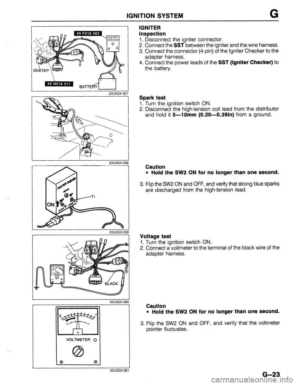
IGNITER
Inspection
1. Disconnect the igniter connector.
2. Connect the
SST between the igniter and the wire harness.
3. Connect the connector (4-pin) of the Igniter Checker to the
adapter harness.
4. Connect the power leads of the
SST (Igniter Checker) to
the battery.
Spark test
1. Turn the ignition switch ON.
2. Disconnect the high-tension coil lead from the distributor
and hold it
5--10mm (0.20-0.39in) from a ground.
Caution
l Hold the SW2 ON for no longer than one second.
3. Flip the SW2 ON and OFF, and verify that strong blue sparks
are discharged from the high-tension lead.
Voltage test
1. Turn the ignition switch ON.
2. Connect a voltmeter to the terminal of the black wire of the
adapter harness.
Caution
l Hold the SW2 ON for no longer than one second.
3. Flip the SW2 ON and OFF, and verify that the voltmeter
pointer fluctuates.
G-23
Page 469 of 1164

STARTING SYSTEM G
WEAR LIMIT
/ -- _._- .------
03UOGX-07L i
-----.
i
03UOGX 076
03UOGX-07
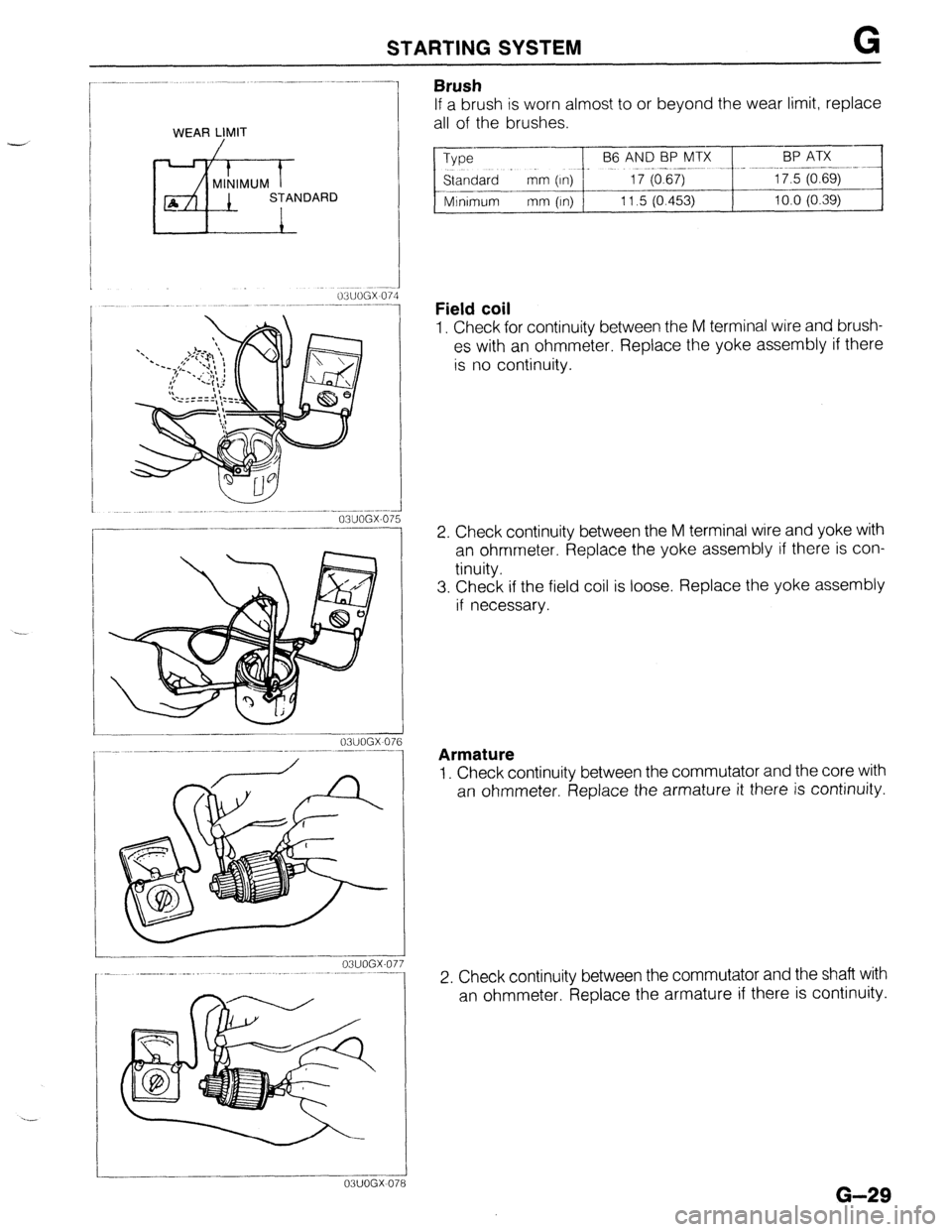
Brush
If a brush is worn almost to or beyond the wear limit, replace
all of the brushes.
Type
--pFeE?~Ix _~~_ -.~+~~zE~~:
Standard - mm (In) 1
--.-
Minimum mm (In) 11.5 (0.453) 10.0 (0.39)
Field coil
1. Check for continuity between the M terminal wire and brush-
es with an ohmmeter. Replace the yoke assembly if there
is no continuity.
2. Check continuity between the M terminal wire and yoke with
an ohmmeter. Replace the yoke assembly if there is con-
tinuity.
3. Check if the field coil is loose. Replace the yoke assembly
if necessary.
Armature
1. Check continuity between the commutator and the core with
an ohmmeter. Replace the armature it there is continuity.
2. Check continuity between the commutator and the shaft with
an ohmmeter. Replace the armature if there is continuity.
G-29