MAZDA PROTEGE 1992 Owner's Manual
PROTEGE 1992
MAZDA
MAZDA
https://www.carmanualsonline.info/img/28/57077/w960_57077-0.png
MAZDA PROTEGE 1992 Owner's Manual
Page 876 of 1164
T SWITCHES
03UOTX-026
H&N CAP
03UOTX-02 8
03UOTX-02s
SWITCH
Removal / Installation
Ignition switch
1. Remove the negative battery cable.
2. Remove the steering column cover.
3. Remove the screw and the ignition switch.
4. Install in the reverse order of removal.
Hazard warning switch
1. Remove the meter hood.
2. Remove the screws and the hazard switch.
3. Install in the reverse order of removal.
Cruise control switch
(set/coast and resume/accel switch)
1. Remove the steering wheel cap.
2. Remove the cruise control switch as shown in the figure.
3. Install in the reverse order of removal.
Inspection
1. Check for continuity between the terminals with an
ohmmeter.
Remote control door mirror switch
CLASS DIRECTION a b c d i k I
UP o---o
0 0
1 UP
I I lo! I-l7ol
o----O: Indicates continuity
T-20
Page 877 of 1164
SWITCHES T
e C a
~ f
d b
03UOTX-03
13UOTX-OC
WARNING SW
03UOTX-0:
b a d
h
13UOTX-01
03UOTX-03
Rear window defroster switch
O----0: Indicates continuity
Ignition switch
O----0: Indicates continuity
Hazard warning switch
C--O: Indicates continuity
Cruise control main switch
I I OFF
I ON l% I I ,
G----O: Indicates continuity
2. Measure the switch resistance with an ohmmeter.
Cruise control switch
Switch Condition Check terminal
a-b
OFF
co
RESUMElACCEL
ON 910n
OFF Co SET/COAST ON 2400
o---O: Indicates continuity
T-21
Page 879 of 1164
SWITCHES T
COMBINATION SWITCH
Removal / Installation (Except Canada without cruise control system)
1. Remove in the order shown in the figure.
2. Install in the reverse order of removal.
1. Horn cap
2. Steering wheel
3. Steering column cover 4. Combination switch
Disassembly I Assembly , . , . . . . . . . . . . page T-24
Inspection .,......,.,....,.*..*..,.,......... page T-27
T-23
Page 880 of 1164
T SWITCHES
USA WITHOUT CRUISE CONTROL SYSTEM
4
P
WITH CRUISE CONTROL SYSTEM
4
P
Disassembly / Assembly
1. Remove in the order shown in the figure.
2. install in the reverse order of removal.
6
1.
Cancel cam
2.
Spring
3. Slip ring assembly
1 WOTX-01
4. Wiper lever
5. Light unit
T-24
Page 881 of 1164
SWITCHES T
Removal / Installation (Canada without cruise control system)
1. Remove in the order shown in the figure.
2. Install in the reverse order of removal.
1. Horn cap
2. Steering wheel
3. Steering column cover 4. Combination switch
13UOTX-01;
Disassembly / Assembly . . . . . . . . . . . . . page T-26
Inspection . . , . . . . . . . . . . . . . . . . . . . . . . . . . . . ,. . , . page T-28
T-25
Page 882 of 1164
T SWITCHES
Disassembly / Assembly
1. Remove in the order shown in the figure.
2. Install in the reverse order of removal.
I
CANADA WITHOUT CRUISE CONTROL SYSTEM
13UOTX-01 8
1. Cancel cam
2. Spring 3. Wiper lever
4. Light unit -
T-26
Page 883 of 1164
SWITCHES T
I 03UOTX-040
HU
HL BA
E HEAD
BTN
1 BUOTX-01
WITHOUT CRUISE CONTROL SYSTEM
p=j==gz$~
WITH CRUISE CONTROL SYSTEM
03UOTX-042
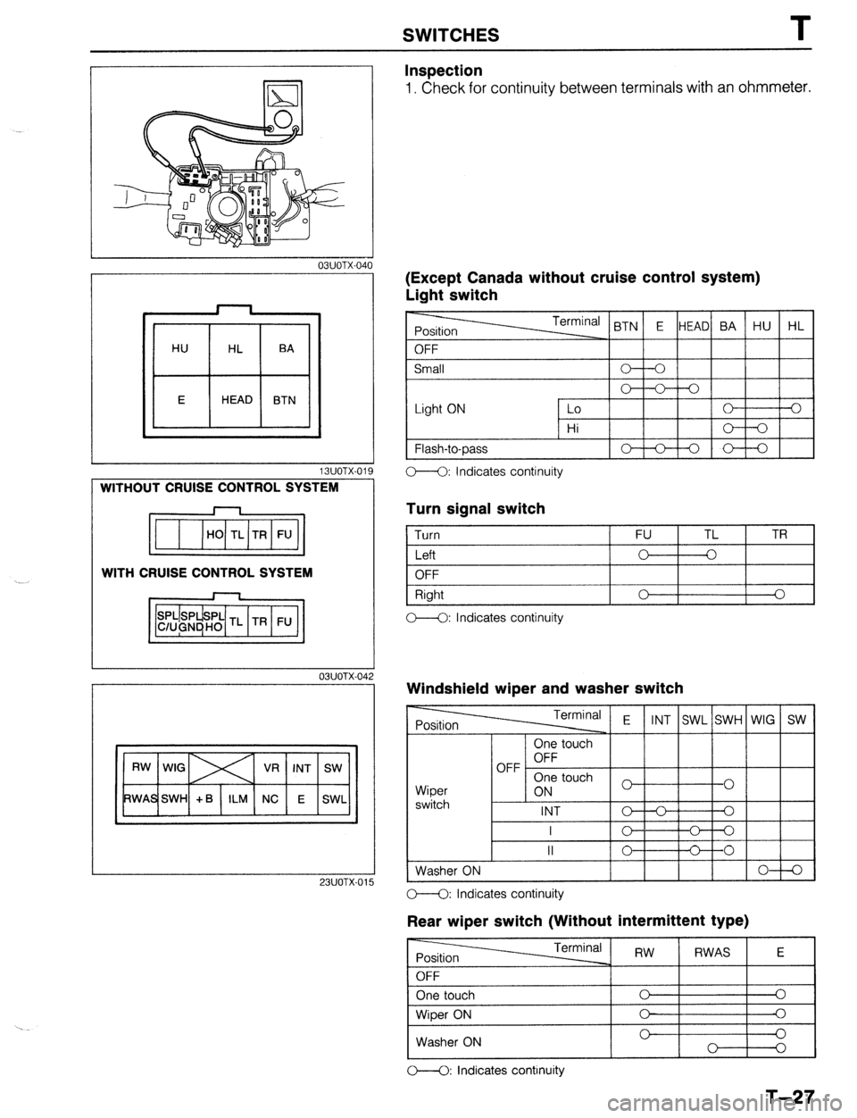
Inspection
1. Check for continuity between terminals with an ohmmeter.
IExcept Canada without cruise control system)
Jght switch
t OFF < BTN E HEAD BA HU HL
Small
Light ON 0 V-0
Lo 0 3
Hi o----o
1 Flash-to-Dass
I-lo-+-oI I
C--Q: Indicates continuity
Turn signal switch
1 Turn 1 FU TL 1 TR
I
I Left
I o-+--o I I
1 OFF
Right
C--O: Indicates continuity 0 I I
0
Windshield wiper and washer switch
Terminal E
INT SWL SWH WIG SW
Wioer
I 1 6N 3 touch
1-01 I
switch I -
INT o--o Q
I
c- o---o
II 0 C----O
Washer ON
I I I I I 0-l-Q 23UOTX-01 O--O: Indicates continuity
Rear wiper switch (Without intermittent type)
O----O: Indicates continuity
T-27
Page 884 of 1164
T SWITCHES
, 23UOTX-016
13UOTX.02
L
TL
FU TR
OBUOTX-I 76
03UOTX-I 7
03uolx17
Rear wiper switch (With intermittent type)
-
Position Terminal RW
RWAS E
OFF
One touch 0 0
Wiper ON 0 0
Washer ON 0 0
O--O: Indicates continuity
(Canada without cruise control system)
Light switch
Light ON Lo 0 0
Hi
Flash-to-pass 0 A
” 0
O--O: Indicates continuity
Turn signal switch
1 Turn FU TL TR
I Left
I o---k-o I I
OFF
Right
OFF 0 0
0 A
-0
o--<>: Indicates continuity
Windshield wiper and washer switch
Wiper
switch One touch
OFF OFF
One touch
ON
INT
L I - I -
I I I (LOW) 0 ) 1 0 1
I I lo-+-al
1 Washer ON I I I IO-+0
o---O: Indicates continuity
Rear wiper switch
r------ -rrr.m;nn, I I I - I RW 1 RWAS I E I
I One touch I c I
Wiper ON 0
0
Washer ON 0 0
0
0
M: Indicates continuity
T-28
Page 887 of 1164
CANADA lDAYTIME RUNNING LIGHTS
E-2
BATTFRY
UN CONTROL UNIT
G (Fl G/Y IF) G/R IF1
INSTRUMENT INSTRUMENT
CLUSTER Cl USTER
(SECTION C) (SECTION C)
WITH
CRUISE CONTROL ‘HEADL1GHTS E-2
MAIN
BOA
COMBINATION EXCEPT
SWITCH ~~;~~~;ENT/cnNnon
(SECTION cl
(!I
cI 4*0*
r----- ORL CONTROL 7
(SECTION E-31
-02 COMBINATION E-03 HEADLIGHT LH(F) E-04 HEADLIGHT FIti
SWITCH (Fl E-05 HEADLIGHT “Et$
-06 TAILLIGHT “E:;;
Page 890 of 1164
EXTERIOR LIGHTING SYSTEM
Turn and Hazard Warning Light
Circuit diagram
BTURN 6; HAZARD FLASHER LIGHTS F-l
BLUE3 TRADE NUMBER
FRONT TURN: 1157 (27W)
REAR TURN : 1156 (27W)
HAZARD SWITCH
ILLUMINATION LAMP:
REFER TO SECTION I-4
-01 TURN SWITCH (F) F-02 FLASHER UNIT (F)
I=] (++&I+YI [ml
WITH CHlJISE CONTROL
WITHOUT CRUISE
CONTROL
-05 HAZARD SWITCH (I) E-12 REAR TURN L$“1’ E-13 REAR TURN ‘R$-$
B R/B
G
03UOTX-052
T-34


