distributor MAZDA PROTEGE 1992 Workshop Manual
[x] Cancel search | Manufacturer: MAZDA, Model Year: 1992, Model line: PROTEGE, Model: MAZDA PROTEGE 1992Pages: 1164, PDF Size: 81.9 MB
Page 38 of 1164
Bl ENGINE TUNE-UP PROCEDURE
13UOBi-036
-i
OWOBX-261
13UOBl-08
LOCK BOLTS
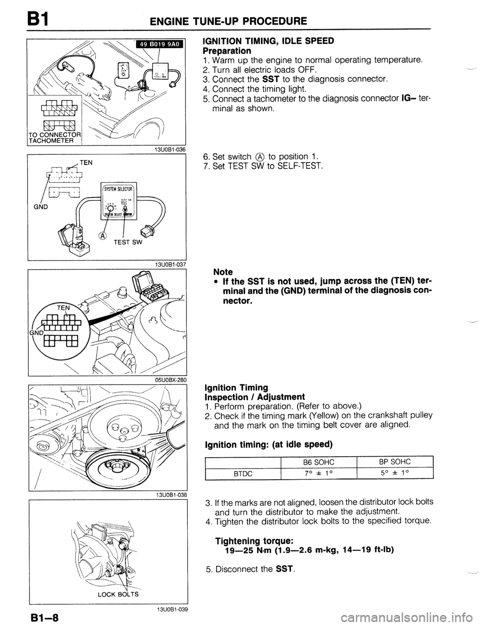
IGNITION TIMING, IDLE SPEED
Preparation
1, Warm up the engine to normal operating temperature.
2. Turn all electric loads OFF.
3. Connect the
SST to the diagnosis connector.
4. Connect the timing light.
5. Connect a tachometer to the diagnosis connector
IG- ter-
minal as shown.
6. Set switch @ to position 1.
7. Set TEST SW to SELF-TEST.
Note
l If the SST is not used, jump across the (TEN) ter-
minal and the (GND) terminal of the diagnosis con-
nector.
Ignition Timing
Inspection / Adjustment
1. Perform preparation. (Refer to above.)
2. Check if the timing mark (Yellow) on the crankshaft pulley
and the mark on the timing belt cover are aligned.
Ignition timing: (at idle speed)
B6 SOHC
BTDC 70 f 10 BP SOHC
5O f lo
3. If the marks are not aligned, loosen the distributor lock bolts
and turn the distributor to make the adjustment.
4. Tighten the distributor lock bolts to the specified torque.
Tightening torque:
19-25 N.m (1.9-2.6 m-kg, 14-19 ft-lb)
5. Disconnect the SST.
Bl-8
13UOBl-039
Page 48 of 1164
Bl ON-VEHICLE MAINTENANCE
Harnesses
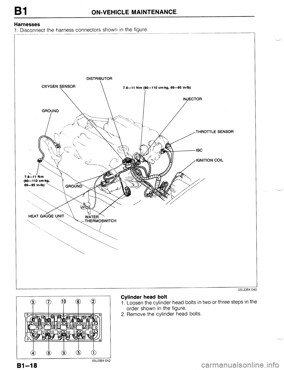
1. Disconnect the harness connectors shown in the figure.
DISTRIBUTOR
OXYGEN SENSOR
7.8-l 1 N.m (80-I 10 cm-kg, 69-95 in-lb)
I
INJECTOR
GROUND
/
7.8-11 N-m
(80-110 cm-kg,
HEAT GAijijE
Cylinder head bolt
1, Loosen the cylinder head bolts in two or three steps in the
order shown in the figure.
2. Remove the cylinder head bolts.
Page 70 of 1164
Bl DISASSEMBLY
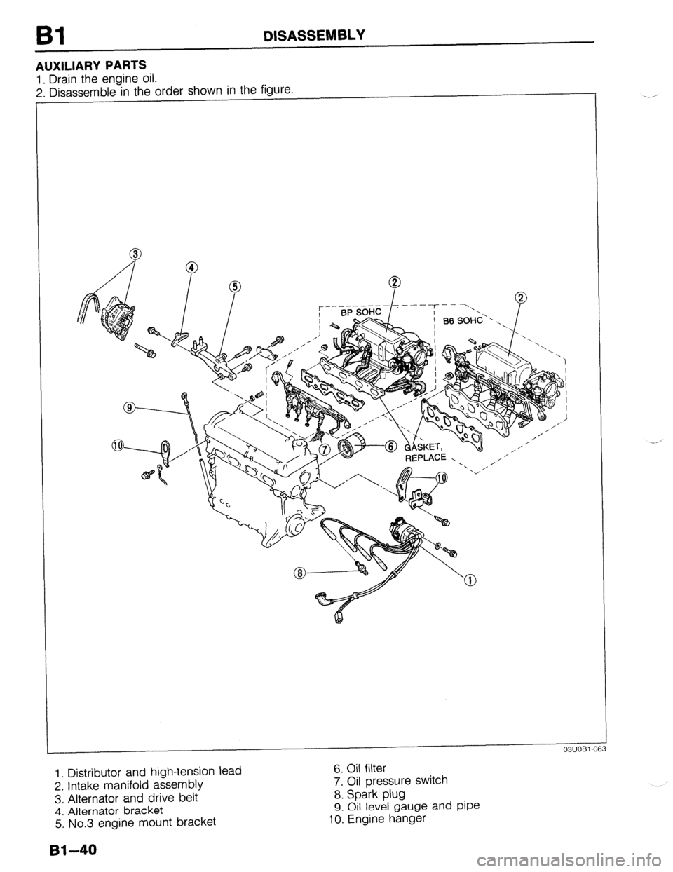
AUXILIARY PARTS
1. Drain the engine oil.
2. Disassemble in the order shown in the figure.
- REPLACE - ’ ,/ I’
1. Distributor and high-tension lead
2. Intake manifold assembly
3, Alternator and drive belt
4. Alternator bracket
5. No.3 engine mount bracket 6. Oil filter
7. Oil pressure switch
8. Spark plug
9. Oil level gauge and pipe 10. Engine hanger
61-40
Page 121 of 1164

ASSEMBLY Bl
03UOBl-16
03UOB1.21 38
Injector and Distribution Pipe Assembly (BP SOHC)
1. Install the injector and distribution pipe assembly with new
insulators.
Tightening torque:
19-25 N-m (1.9-2.6 m-kg, 14-19 ft-lb)
Intake Manifold Assembly
1, Remove all foreign material from the intake manifold con-
tact surface.
2. Install a new gasket and the intake manifold assembly.
Tightening torque:
19-25 N*m (1.9-2.6 m-kg, 14-19 ft-lb)
Distributor and High-tension Lead
1. Apply engine oil to the O-ring, and position it on the dis-
tributor.
2. Apply engine oil to the blade.
3. Install the distributor with the blade fit into the camshaft
groove.
4. Temporarily, loosely tighten the distributor installing bolt.
5. Adjust the ignition timing after engine installation.
(Refer to Section G.)
6. Connect the high-tension leads.
81-91
Page 140 of 1164
82 ENGINE TUNE-UP PROCEDURE
03UOB2-013
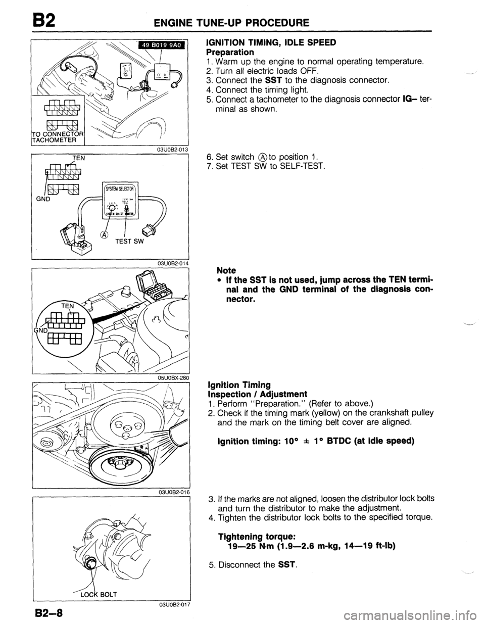
IGNITION TIMING, IDLE SPEED
Preparation
1. Warm up the engine to normal operating temperature.
2. Turn all electric loads OFF.
3. Connect the
SST to the diagnosis connector.
4. Connect the timing light.
5. Connect a tachometer to the diagnosis connector
IO- ter-
minal as shown.
TEN
03UOB2-01
I
-&k BOLT
0311082-01’
82-8
6. Set switch @to position 1.
7. Set TEST SW to SELF-TEST.
Note
l If the SST is not used, jump across the TEN termi-
nal and the GND terminal of the diagnosis con-
nector.
Ignition Timing
Inspection / Adjustment
1. Perform “Preparation.” (Refer to above.)
2. Check if the timing mark (yellow) on the crankshaft pulley
and the mark on the timing belt cover are aligned.
Ignition timing: 10 * f lo BTDC (at Idle speed)
3. If the marks are not aligned, loosen the distributor lock bolts
and turn the distributor to make the adjustment.
4. Tighten the distributor lock bolts to the specified torque.
Tightening torque:
19-25 N*m (1 .Q-2.6 m-kg, 14-19 ft-lb)
5. Disconnect the SST.
Page 154 of 1164

B2 ON-VEHICLE MAINTENANCE
HLA
Removal / Installation
1. Disconnect the negative battery cable.
2. Remove in the order shown in the figure, referring to
Removal Note.
3. install in the reverse order of removal, referring to Installation Note --- ----- -__ __-- ,‘.
11.3-14.2 N.m
(1.15-1.45 m-\g, 100-126 in-lb)
49-61
(5.0~6.2,-36-45)
4.9-6.6 N.m
(50-90 cm-kg, 43-76 in-lb)
7.6All N-m
(80-110 cm-kg, 69-95 in-lb) 1 Q’-25
(1.9-2.6, 14-19)
N.m (m-kg, ft-lb)
0311082-03
1. High-tension lead
10. Cylinder head cover
2. Distributor
Installation Note..
....................
Installation Note.. ......................
page 62-25
11. Camshaft pulley
3. P/S and/or A/C drive belt
Removal note ..........................
Removal / Installation..
.............. page E32-
6
Installation Note .......................
4. Alternator drive belt
12. Seal plate
Removal / Installation
......... . ...... page B2- 6
13. Camshaft
5. Water pump pulley
Removal Note.. ........................
6. Timing belt cover, upper
Installation Note.. .....................
7. Timing belt cover, middle
14. HLA
8. Spark plug
Removal note ..........................
9. Timing belt
Installation
Note.. .....................
Removal Note.. .........................
page B2-18 Inspection
................................
Installation Note.. ......................
page B2-20
7
page 62-19
page 82-23
page 82-24
page B2-23
page 62-23
page B2-23
page B2-23 ‘--’
page 82-60
82-22
Page 155 of 1164

ON-VEHICLE MAINTENANCE 82
I 05UOBX-049
05UOBX-C
05UOBX-0
03UOB2-1
Removal note
Camshaft pulley
1, Hold the camshaft with a wrench at hexagonal portion.
2. Remove the camshaft pulley lock bolt.
3. Remove the camshaft pulley.
Camshaft
1. Loosen the camshaft cap bolts in two or three steps in the
order shown in the figure.
2. Remove the camshaft caps.
3. Remove the camshaft.
4. Remove the camshaft oil seal from the camshaft.
HLA
Caution
l Mark the HLA with a felt pen so that they can be rein-
stalled in the position from which they were
removed.
1. Remove the HLA from the cylinder head.
Installation note
HLA
1. Apply clean engine oil to the friction surfaces.
2. If the HLA are being reused, install them in the position from
which they were removed.
3. Verify that the HLA move smoothly in their bores.
Camshaft
Note
l The intake camshaft is grooved for the distributor
drive.
1. Apply clean engine oil to the camshaft journals and bearings.
2. Install the camshaft in position.
82-23
Page 157 of 1164

ON-VEHICLE MAINTENANCE B2
05UOBX-05
BLA-DE 0-dlNG
Steps After Installation
1. Connect the negative battery cable.
2. Start the engine and check as follows:
l Ignition timing. (Refer to page 82-8.) 3. Install the camshaft pulley lock bolts.
4. Hold the camshaft with a wrench.
5. Tighten the camshaft pulley lock bolt.
Tightening torque:
49-61 N-m (5.0-6.2 m-kg, 36-45 ft-lb)
Distributor
1. Apply grease to a new O-ring and the blade.
2. Install the distributor and loosely tighten the installation bolt.
3. Connect the distributor connector.
0311082-039
B2-25
Page 174 of 1164
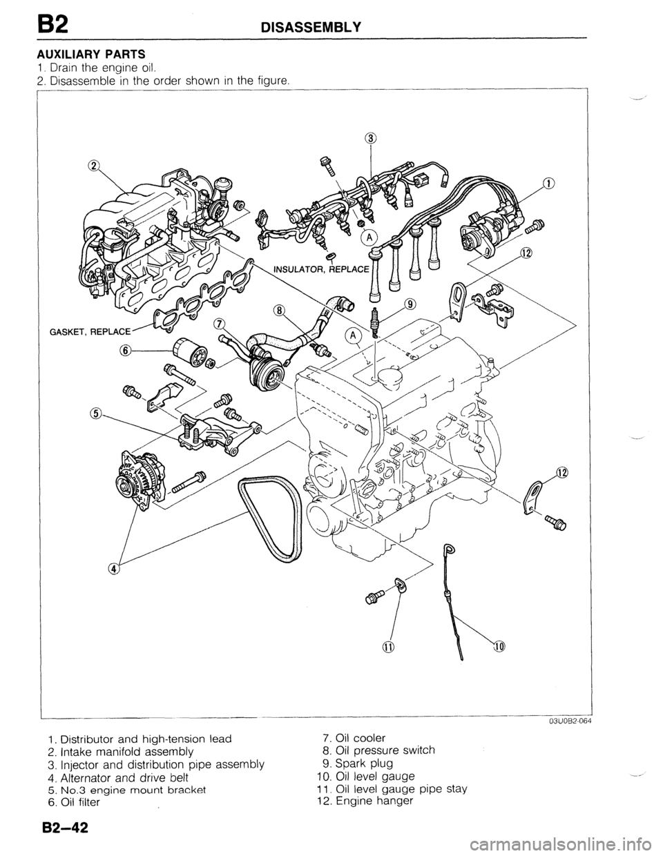
B2 DISASSEMBLY
AUXILIARY PARTS
1, Drain the engine oil.
2. Disassemble in the order shown in the figure
GASKET, REPLACE ..______-.
-___ -
03UOB2-064
1. Distributor and high-tension lead 7. Oil cooler
2. Intake manifold assembly 8. Oil pressure switch
3. Injector and distribution pipe assembly 9. Spark plug
4. Alternator and drive belt 10. Oil level gauge
5. No.3 engine mount bracket 11. Oil level gauge pipe stay
6. Oil filter 12. Engine hanger
82-42
Page 222 of 1164

B2 ASSEMBLY
03UOB2-15:
I
03UOB2-121
3. Connect the harness and hose.
--’
Distributor and High-tension Lead
1. Apply grease to a new O-ring and the blade.
2. Install the distributor and loosely tighten the installation bolts.
3. Connect the high-tension leads.
82-90