MERCEDES-BENZ EQC SUV 2021 Owners Manual
Manufacturer: MERCEDES-BENZ, Model Year: 2021, Model line: EQC SUV, Model: MERCEDES-BENZ EQC SUV 2021Pages: 453, PDF Size: 8.68 MB
Page 351 of 453
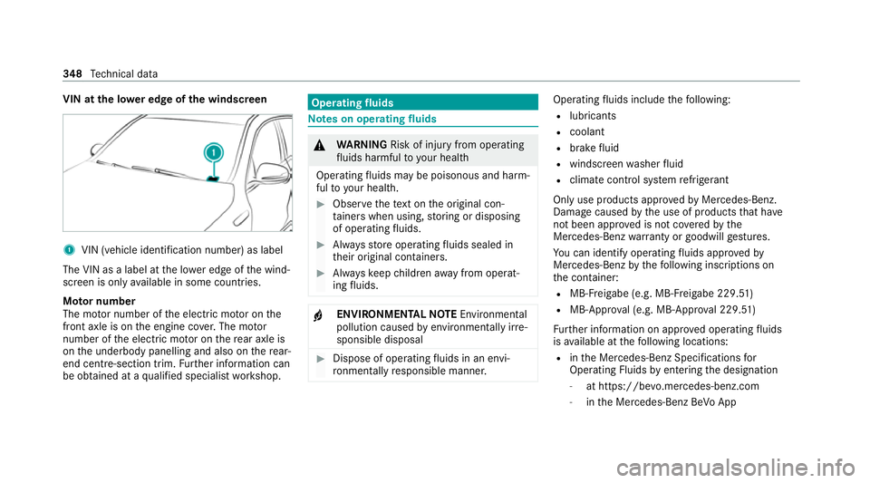
VIN at the lo
wer edge of the windscreen 1
VIN (vehicle identi fication number) as label
The VIN as a label at the lo wer edge of the wind‐
screen is only available in some countries.
Mo tor number
The mo tor number of the electric mo tor on the
front axle is on the engine co ver.The mo tor
number of the electric mo tor on there ar axle is
on the underbody panelling and also on there ar-
end centre-section trim. Further information can
be obtained at a qualified specialist workshop. Operating
fluids Note
s on operating fluids &
WARNING Risk of inju ryfrom operating
fl uids harmful to your health
Operating fluids may be poisonous and harm‐
ful to yo ur health. #
Obser vethete xt on the original con‐
ta iners when using, storing or disposing
of operating fluids. #
Alw aysst ore operating fluids sealed in
th eir original conta iners. #
Alw ayske ep children away from operat‐
ing fluids. +
ENVIRONMEN
TALNO TEEnvironmental
pollution caused byenvironmen tally ir re‐
sponsible disposal #
Dispose of operating fluids in an envi‐
ro nmentally responsible manner. Operating
fluids include thefo llowing:
R lubricants
R coolant
R brake fluid
R windsc reen washer fluid
R climate cont rol sy stem refrigerant
Only use products app rove dby Mercedes-Benz.
Damage caused bythe use of products that ha ve
not been appr oved is not co veredby the
Mercedes-Benz warranty or goodwill gestures.
Yo u can identify operating fluids appr ovedby
Mercedes-Benz bythefo llowing insc ript ions on
th e conta iner:
R MB- Freigabe (e.g. MB-Fr eigabe 229.51 )
R MB-Appr oval (e.g. MB-App rova l 229.51)
Fu rther information on appr oved operating fluids
is available at thefo llowing locations:
R inthe Mercedes-Benz Specifications for
Operating Fluids byentering the designation
- at https://be vo.mercedes-benz.com
- inthe Mercedes-Benz BeVo App 348
Tech nical da ta
Page 352 of 453
R
at a qualified specialist workshop Note
s on brake fluid Obser
vethe no tes on operating fluids
(/ page 348). &
WARNING Risk of an accident due to
va pour poc kets form ing in the brake sys‐
tem
The brake fluid cons tantly absorbs moi sture
from the air. This lo wersthe boiling point of
th e brake fluid. If the boiling point is too lo w,
va pour poc kets may form inthe brake sys‐
te m when the brakes are applied hard.
This impairs the braking ef fect. #
Have the brake fluid rene we d at the
specified inter vals. Ha
ve the brake fluid regularly replaced at a
qu alified specialist workshop.
Only use a brake fluid appr ovedby Mercedes-
Benz according toMB-F reigabe or MB-Appr oval
33 1.0. Coolant
Note
s on coolant
Obser vethe no tes on operating fluids
(/ page 348). &
WARNING Risk offire ‑ and inju ryfrom
antifreeze
If antifreeze comes into contact with hot
component parts in the engine compart‐
ment, it may ignite. #
Allow the drive sy stem tocool down
before youto p up the antif reeze. #
Make sure that no antifreeze spills out
next tothefiller opening. #
Thoroughly clean the antif reeze from
component parts before starting the
ve hicle. *
NO
TEDama gecaused byincor rect cool‐
ant #
Only use coolant that has been pre‐
mixed with therequ ired antifreeze pro‐
te ction.
Information on coolant is available at thefo l‐
lowing locations:
R inthe Mercedes-Benz Specification for
Operating Fluids 310.1
- at https://be vo.mercedes-benz.com
- inthe Mercedes-Benz BeVo app
R at a qualified specialist workshop *
NO
TEOverheating at high outside tem‐
peratures If an inapp
ropriate coolant is used, the
engine cooling sy stem is not suf ficiently pro‐
te cted against overheating and cor rosion at
high outside temp eratures. #
Alw ays use coolant appr ovedby
Mercedes-Benz. Te
ch nical da ta349
Page 353 of 453
#
Obser vethe instructions in the
Mercedes-Benz Specifications for Oper‐
ating Fluids 310.1. Ha
ve the coolant regularly replaced at a qualified
specialist workshop.
Proportion of antifreeze concentrate in the
engine cooling sy stem:
R A minimum of 50% (antifreeze pr otection
down toabout -37°C)
R A maximum of 55% (antifreeze pr otection
down to-45°C) Note
s on windscreen washer fluid Obser
vethe no tes on operating fluids
(/ page 348). &
WARNING Risk offire and injury from
windsc reen washer concentrate
Wi ndsc reen washer concentrate is highly
fl ammable. If it comes into con tact wi thhot
components, it may ignite. #
Make sure that windsc reen washer con‐
centra teis not spilled near tothefiller
opening. *
NO
TEDama getotheex terior lighting
due tounsuitable windsc reen washer
fl uid Uns
uitable windsc reen washer fluids may
damage the plastic sur face of theex terior
lighting. #
Only use windscreen washer fluids
which are also suitable for use on plas‐
tic sur faces, e.g. MB SummerFit or MB
Wi nterFit. *
NO
TEBlocked spr aynozzles caused by
mixing windscreen washer fluids #
Do not mix MB SummerFit and MB Win‐
te rFit with other windscreen washer flu‐
ids. Do not use distilled or de-ionised
water.Other‐
wise, thefill le vel sensor may be triggered er ro‐
neously.
Re commended windscreen washer fluid:
R abo vefreezing point: e.g. MB SummerFit
R below freezing point: e.g. MB WinterFit
Fo rth e cor rect mixing ratio, referto the informa‐
tion on the antif reeze conta iner.
Mix washer fluid with windsc reen washer fluid all
ye ar round. Ve
hicle data Ve
hicle dimensions The heights speci
fied may vary as a result of the
fo llowing factors:
R tyres
R load
R condition of the suspension
R optional equipment 350
Tech nical da ta
Page 354 of 453
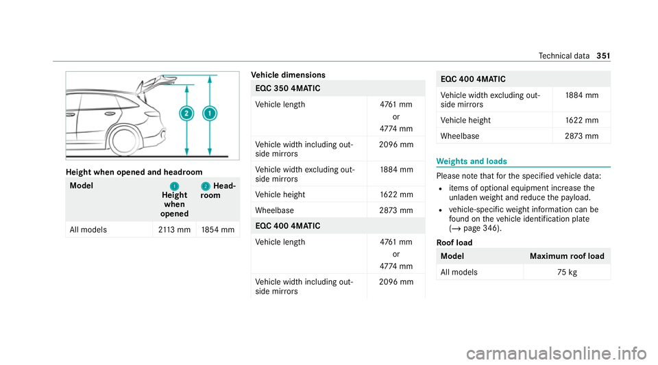
Height when opened and headroom
Model
1
1
Height
when
opened 2
2
Head‐
ro om
All models 2113 mm 1854 mm Ve
hicle dimensions EQC 350 4MATIC
Ve
hicle lengt h4 761 mm
or
47 74 mm
Ve hicle width including out‐
side mir rors 2096 mm
Ve hicle width excluding out‐
side mir rors 18
84 mm
Ve hicle height 1622 mm
Wheelbase 2873 mm EQC 400 4MATIC
Ve
hicle lengt h4 761 mm
or
47 74 mm
Ve hicle width including out‐
side mir rors 2096 mm EQC 400 4MATIC
Ve
hicle width excluding out‐
side mir rors 18
84 mm
Ve hicle height 1622 mm
Wheelbase 2873 mm We
ights and loads Please no
tethat forth e specified vehicle data:
R items of optional equipment increase the
unladen weight and reduce the pa yload.
R vehicle-specific weight information can be
fo und on theve hicle identification plate
(/ page 346).
Ro of load Model
Maximumroof load
All models 75kg Te
ch nical da ta351
Page 355 of 453
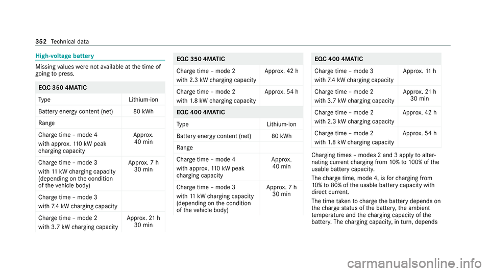
High-voltage battery
Missing
values werenot available at the time of
going topress. EQC 350 4MATIC
Ty
pe Lithium-ion
Battery energy con tent (net) 80 kWh
Ra nge
Charge time – mode 4
wi th appr ox.11 0 kW peak
ch arging capacity App
rox.
40 min
Charge time – mode 3
wi th 11 kW charging capacity
(depending on the condition
of theve hicle body) Appr
ox. 7 h
30 min
Charge time – mode 3
wi th 7.4 kW charging capacity
Char getime – mode 2
wi th 3.7 kW charging capacity App
rox. 21 h
30 min EQC 350 4MATIC
Charge time – mode 2
with 2.3 kW
charging capacity App
rox. 42 h
Charge time – mode 2
wi th 1.8 kW charging capacity App
rox. 54 h EQC 400 4MATIC
Ty
pe Lithium-ion
Battery energy con tent (net) 80 kWh
Ra nge
Charge time – mode 4
wi th appr ox.11 0 kW peak
ch arging capacity App
rox.
40 min
Charge time – mode 3
wi th 11 kW charging capacity
(depending on the condition
of theve hicle body) Appr
ox. 7 h
30 min EQC 400 4MATIC
Charge time – mode 3
wi
th 7.4 kW charging capacity App
rox. 11 h
Char getime – mode 2
wi th 3.7 kW charging capacity App
rox. 21 h
30 min
Charge time – mode 2
with 2.3 kW charging capacity App
rox. 42 h
Charge time – mode 2
wi th 1.8 kW charging capacity App
rox. 54 h Charging times – modes 2 and 3 apply
toalter‐
nating cur rent charging from 10%to 100% of the
usable bat tery capacity.
The charge time, mode 4, is forch arging from
10 %to 80% of the usable battery capacity with
direct cur rent.
The time take nto charge the battery depends on
th ech arge status of the batter y,the ambient
te mp erature and thech arging capacity of the
batter y.The charging capacity, in turn, depends 352
Tech nical da ta
Page 356 of 453
on
the supply voltage, the cur rent intensity and
th e type of po wer supp ly.
The ratedvo ltage range foryo ur vehicle can be
fo und on the information label in the soc ket
co ver (/ page163). Tr
ailer hitch Gene
ral no tes on the trailer hit ch Modifications
tothe engine cooling sy stem may
be necessar y,depending on theve hicle model.
The retrofitting of a trailer hitch is only pe rmissi‐
ble if a towing capacity is specified in your vehi‐
cle documents.
Fu rther information can be obtained at a quali‐
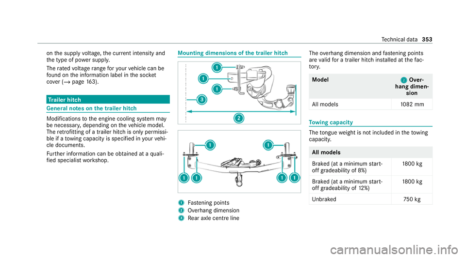
fi ed specialist workshop. Mounting dimensions of
the trailer hit ch 1
Fastening points
2 Overhang dimension
3 Rear axle centre line The
overhang dimension and fastening points
are valid for a trailer hitch ins talled at thefa c‐
to ry. Model
2 2Over‐
hang dimen‐ sion
All model s1 082 mm To
wing capacity The
tongue weight is not included in theto wing
capacity. All models
Braked (at a minimum
start-
off gradeability of 8%) 18
00 kg
Braked (at a minimum start-
off gradeability of 12%) 18
00 kg
Unb rake d7 50kg Te
ch nical da ta353
Page 357 of 453
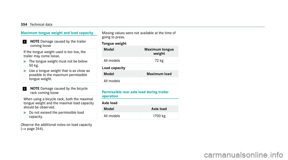
Maximum
tongue weight and load capacity *
NO
TEDama gecaused bythe trailer
coming loose If
th eto ngue weight used is too lo w,the
trailer may come loose. #
The tongue weight must not be below
50 kg. #
Use a tongue weight that is as close as
possible tothe maximum permissible
to ngue weight. *
NO
TEDama gecaused bythe bicycle
ra ck coming loose When using a bicycle
rack , bo th th e maximal
to ngue weight and the maximal load capacity
should be obser ved. #
Do not exceed the permissible load
capacity. Obser
vethe additional no tes on load capacity
(/ page 244). Missing
values werenot available at the time of
going topress.
To ngue weight Model
Maximumtongue
we ight
All models 72kg Load capacity
Model
Maximum load
All models Pe
rm issible rear axle load during trailer
operation Axle load
Model
Axle load
All models 1700 kg 354
Tech nical da ta
Page 358 of 453
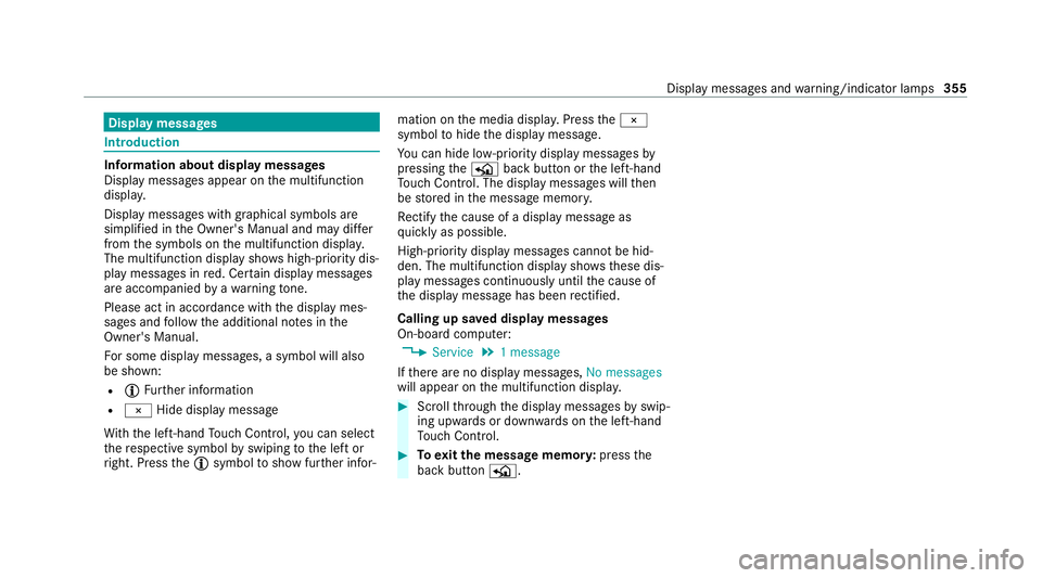
Display messages
Int
roduction In
fo rm ation about display messages
Displ aymessa ges appear on the multifunction
displa y.
Displ aymessa ges with graphical symbols are
simplified in the Owner's Manual and may dif fer
from the symbols on the multifunction displa y.
The multifunction display sho wshigh-priority dis‐
play messages in red. Cer tain display messages
are accompanied byawa rning tone.
Please act in acco rdance with the display mes‐
sages and follow the additional no tes in the
Owner's Manual.
Fo r some display messa ges, a symbol will also
be shown:
R Õ Further information
R ¨ Hide display message
Wi th th e left-hand Touch Control, you can select
th ere spective symbol byswiping tothe left or
ri ght. Press theÕ symbol toshow fur ther infor‐ mation on
the media displa y.Press the¨
symbol tohide the display message.
Yo u can hide lo w-priority display messages by
pressing theP back button or the left-hand
To uch Control. The displ aymessa ges will then
be stored in the message memor y.
Re ctify the cause of a display message as
qu ickly as possible.
High-priority display messages cannot be hid‐
den. The multifunction display sho wsthese dis‐
play messages continuously until the cause of
th e display message has been rectified.
Calling up sa ved displ aymessages
On-boa rdcompu ter:
4 Service 5
1 message
If th ere are no display messages, No messages
will appear on the multifunction displa y. #
Scroll thro ugh the display messages byswip‐
ing upwards or down wards on the left-hand
To uch Control. #
Toexitth e message memor y:press the
back button P. Display messages and
warning/indicator lamps 355
Page 359 of 453
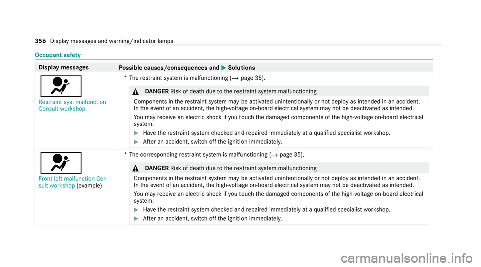
Occupant saf
ety Display messages
Possible causes/consequences and M
MSolutions
6 Restraint sys. malfunction
Consult workshop *T
herestra int sy stem is malfunctioning (/ page 35). &
DANG ER Risk of death due tothere stra int sy stem malfunctioning
Components in there stra int sy stem may be activated unintentionally or not deploy as intended in an accident.
In theev ent of an accident, the high-voltage on-board electrical sy stem may not be deactivated as intended.
Yo u may recei vean electric shock if youto uch the damaged components of the high-voltage on-board electrical
sy stem. #
Have there stra int sy stem checked and repaired immediately at a qualified specialist workshop. #
After an accident, switch off the ignition immediatel y.6
Front left malfunction Con-
sult workshop (exa mp le) *T
he cor responding restra int sy stem is malfunctioning (/ page 35). &
DANG ER Risk of death due tothere stra int sy stem malfunctioning
Components in there stra int sy stem may be activated unintentionally or not deploy as intended in an accident.
In theeve nt of an accident, the high-voltage on-board electrical sy stem may not be deactivated as intended.
Yo u may recei vean electric shock if youto uch the damaged components of the high-voltage on-board electrical
sy stem. #
Have there stra int sy stem checked and repaired immediately at a qualified specialist workshop. #
After an accident, switch off the ignition immediatel y.356
Display messages and warning/indicator lamps
Page 360 of 453
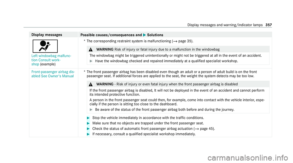
Display messages
Possible causes/consequences and M
MSolutions
6 Left windowbag malfunc-
tion Consult work-
shop (exa mp le) *T
he cor responding restra int sy stem is malfunctioning (/ page 35). &
WARNING Risk of inju ryor fata l injury due toa malfunction in the windowbag
The windowbag might be triggered unintentionally or might not be triggered at all in theeve nt of an accident. #
Have the windowbag checked and repaired immediately at a qualified specialist workshop. Front-passenger airbag dis-
abled See Owner's Manual
*T
he front passenger airbag has been disabled eventh ough an adult or a person of adult build is on the front
passenger seat. If additional forc es are applied tothe seat, thewe ight the sy stem de tects may be too lo w. &
WARNING ‑ Risk of inju ryor eve nfa ta l injury when the front passenger airbag is disabled
If th e front passenger airbag is disabled, It will not be deplo yed in theeve nt of an accident and cannot pe rform
its intended pr otective function.
A person in the front passenger seat could then, forex ample, come into con tact wi th theve hicle interior, espe‐
cially if the person is sitting too close tothe dashboard. #
Beaware of thest atus of the front passenger airbag bo thbefore and during the journe y. #
Stop theve hicle immediately in accordance with the traf fic conditions. #
Makesure that no objects are trapped under the front passenger seat. #
Check thest atus of automatic front passenger airbag actuation (/ page 45).#
If necessar y,consult a qualified specialist workshop immediatel y. Displ
aymessa ges and warning/indicator lamps 357