MERCEDES-BENZ M-CLASS SUV 2011 Owners Manual
Manufacturer: MERCEDES-BENZ, Model Year: 2011, Model line: M-CLASS SUV, Model: MERCEDES-BENZ M-CLASS SUV 2011Pages: 389, PDF Size: 9.22 MB
Page 311 of 389
X
Fold do wnthe rear seat armrest.
Cu ph older :is in the rea rseat armrest. Sun visors
Sun visor overview G
WARNING
Keep the mirror sinthe sun visor scovered
while driving. You coul dotherwis ebedazzled,
which may impair your view of traffic condi-
tions and as aresult could cause an accident. :
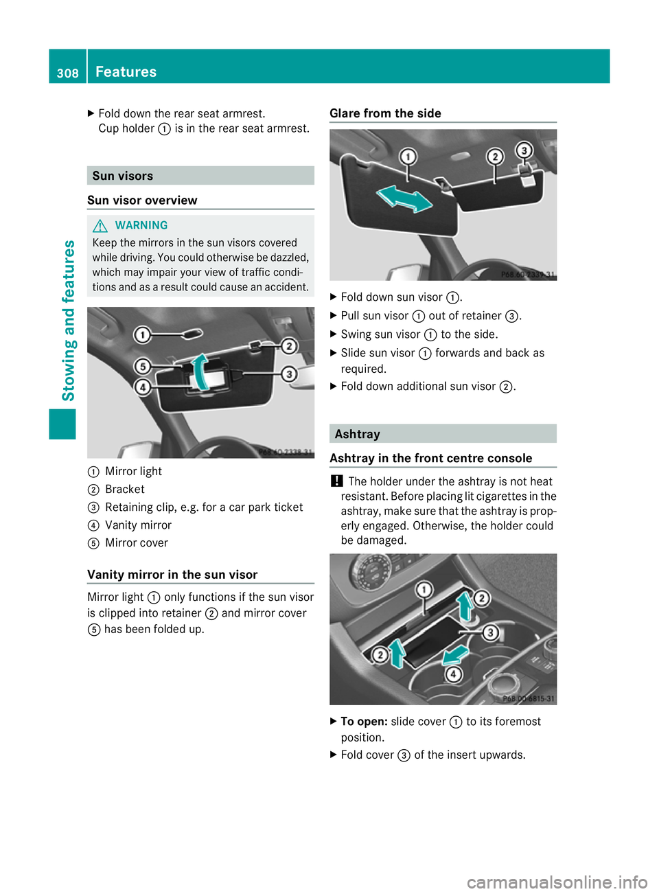
Mirror light
; Bracket
= Retaining clip, e.g. for acar park ticket
? Vanity mirror
A Mirror cover
Vanity mirror in the sun visor Mirror light
:only functions if the sun visor
is clipped into retainer ;and mirror cover
A has been folded up. Glare from the side X
Fold down sun visor :.
X Pull sun visor :out of retainer =.
X Swing sun visor :to the side.
X Slide sun visor :forwards and back as
required.
X Fold down additional sun visor ;. Ashtray
Ashtray in the front centre console !
The holde runder the ashtray is not heat
resistant. Before placing lit cigarettes in the
ashtray, make sure that the ashtray is prop-
erly engaged .Otherwise, the holder could
be damaged. X
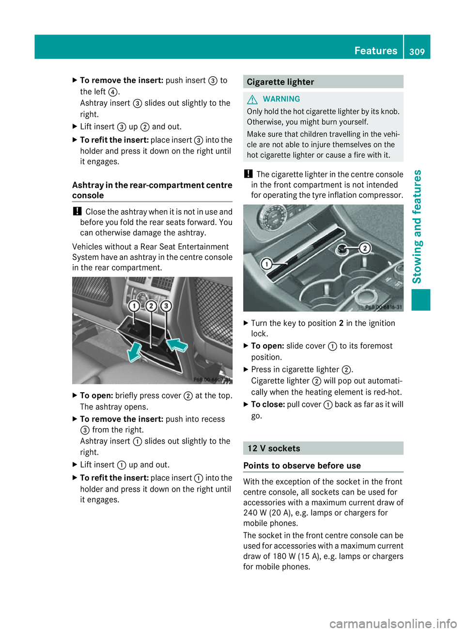
To open: slidecover :to its foremost
position.
X Fold cover =of the inser tupwards. 308
FeaturesStowing and features
Page 312 of 389
X
To remove the insert: push insert=to
the left ?.
Ashtray insert =slides ou tslightly to the
right.
X Lif tinsert =up; and out.
X To refit th einsert: place insert =intothe
holder and press it down on the right until
it engages.
Ash tray in therear-compartme nt centre
console !
Close th eashtra ywhen it is no tinuse and
before you fol dthe rea rseats forward. You
can otherwise damage the ashtray.
Vehicles without aRear Seat Entertainment
System have an ashtra yinthe cen tre console
in the rear compartment. X
To open: briefly pres scover ;at the top.
The ashtray opens.
X To remove th einsert: push into recess
= from the right.
Ashtray insert :slides out slightly to the
right.
X Lif tinsert :up and out.
X To refit the insert: place insert:into the
holder and pres sitdown on the right until
it engages. Cigarette lighter
G
WARNING
Only hold the hot cigarette lighte rbyits knob.
Otherwise, you might burn yourself.
Make sure that children travelling in the vehi-
cle are not able to injure themselves on the
hot cigarette lighter or cause afire with it.
! The cigarette lighter in the centre console
in the front compartment is not intended
for operating the tyre inflation compressor. X
Turn the key to position 2in the ignition
lock.
X To open: slide cover :to its foremost
position.
X Press in cigarette lighter ;.
Cigarette lighter ;will pop out automati-
cally when the heating element is red-hot.
X To close: pull cover :back as far as it will
go. 12
Vsockets
Point stoo bserve befo reuse With the exception of the so
cket in th efront
centr econsole, all socket scan be used for
accessories with amaximum curren tdraw of
240 W(20 A) ,e.g. lamp sorchargers for
mobi lephones.
The socket in the front centre console can be
used for accessories with amaximum current
draw of 18 0W(15A ), e.g .lam ps or chargers
for mobil ephones. Features
309Stowing and features Z
Page 313 of 389
If yo
uuse the sockets for long periods when
the engine is switched off ,the battery may
discharge.
X Tur nthe key to positi on1in the ignition
lock.
i An emergenc ycut-off ensures that the on-
board voltage does not drop too low. If the
on-board voltage is too low, the powe rto
the sockets is automaticall ycut. This
ensure sthat there is sufficien tpower to
star tthe engine.
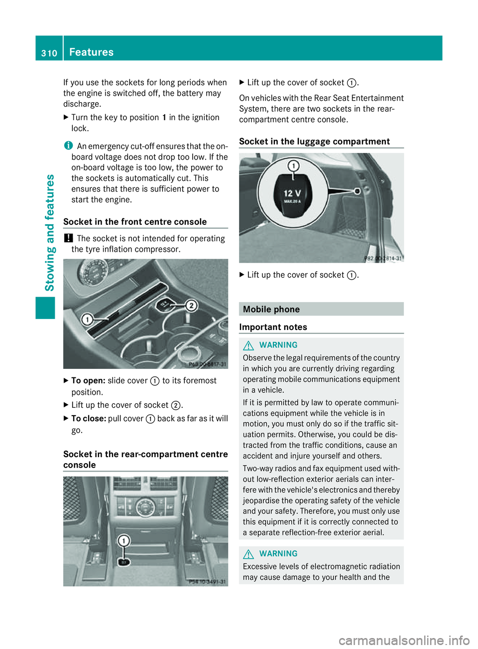
Socket in th efront centre console !
The socke tisn ot intended for operating
the tyr einflation compresso r.X
To open: slide cover :to its foremost
position.
X Lift up the cover of socket ;.
X To clos e:pull cover :back as far as it will
go.
Socket in the rear-compartment centre
console X
Lift up the cover of socket :.
On vehicles with the Rear Seat Entertainment
System, there are two sockets in the rear-
compartment centre console.
Socket in the luggage compartment X
Lift up the cover of socket :. Mobile phone
Important notes G
WARNING
Observe the legal requirements of the country
in which you are currently driving regarding
operating mobile communications equipment
in av ehicle.
If it is permitted by law to operat ecommuni-
cations equipment while the vehicle is in
motion ,you must only do so if the traffic sit-
uation permits. Otherwise, you coul dbedis-
trac tedf rom th etraffic conditions ,cause an
accident and injure yourself and others.
Two-way radios and fax equipment used with-
out low-reflection exterior aerials can inter-
fere with the vehicle's electronics and thereby
jeopardise the operating safety of the vehicle
and your safety. Therefore, you must only use
this equipment if it is correctly connected to
as eparate reflection-f reee xterior aerial. G
WARNING
Excessive level sofelectromagnetic radiation
may cause damage to your health and the 310
FeaturesStowing and features
Page 314 of 389
healt
hofothers. Using an exterior aerial takes
into account current scientific discussions
relating to the possibl ehealth risk posed by
electromagnetic fields.
Mercedes-Ben zrecom mends the use of an
approved exterior aerial .This ensures:
R optimal mobile phone reception quality in
the vehicle
R mutua linfluences between the vehicle
electronics and mobil ephones ar emini-
mised
An exterior aerial has the following advan-
tages:
R it conducts the electromagnetic fields gen-
erated by awireless device to the exterior.
R the field strengt hinthe vehicle interior is
lower than in avehicle that does not have
an exterior aerial.
i There are various mobile phone brac kets
that may be fitted to your vehicle ;insome
cases, these ar ecountry-specific.
i Even if your vehicle is equipped with con-
venience telephony, you can connec ta
Blueto oth®
capable mobil ephone to Audio
20 or COMAND Online via the Bluetooth ®
interfac e.
More information on suitabl emobilephones,
mobile phone brackets and on connecting
Bluetooth ®
capable mobile phones to Audio
20 or COMAND Online can be obtained:
R at your Merc edes-Ben zServ iceC entre
R on the Internet at http://www.mercedes-
benz.com/connect
i The functions and service savailab lewhen
you use the phone depend on you rmobile
phone model and service provider. Inserting th
emobile phone X
Open the telephone compartment
(Y page 298).
X If required by the design of the mobile
phone bracket ,instal lthe slidin gadapter
(Y page 312).
X Insert the mobile phone into the mobile
phone bracket (see the separat emobile
phone bracke tinstallatio ninstructions).
If the mobil ephone is inser tedint he mobile
phone bracket ,you can speak to the person
you ar ecalling using the hands-free system.
i On some mobile phone brackets, you first
have to connect the mobile phone via Blue-
tooth ®
to am obile phone bracke t(see the
separate operating inst ructions for the
mobile phone bracke t).
On these mobile phone brackets, the
mobile phone does not hav etobeinserted
into the bracket for you to be able to use
the telephone functions .Inthis case ,the
charging func tion and aerial func tion are
not available.
Operating th emobile phone You can operate the telephone using the
6 and~ button sonthe multifunc tion
steering wheel. You can operate other mobile
phone func tions via the on-boar dcomputer
(Y page 242).
If you tak ethe key out of the ignition lock ,the
mobile phone stay sonb ut you can no longer
use the hands-free system.
If you are making acall and you would like to
take the key out of the ignition lock, first
remove the mobile phone from the bracket.
Otherwise, the call will be ended.
i When amobile phone bracke tisu sed that
is con nected to the mobile phone via Blue-
tooth ®
:ify ou wan ttocontinue acall in
"Private mode", you have to perform the
necessary steps on the mobile phone (see Features
311Stowingandfeatures Z
Page 315 of 389
the separate mobil
ephone operating
instructions).
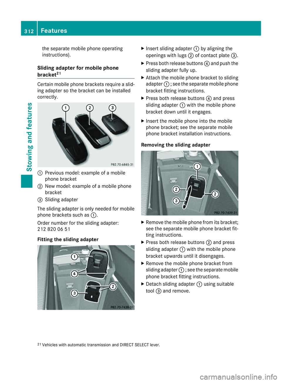
Sliding adapte rfor mobil ephone
bracket 21 Certain mobil
ephone brackets require aslid-
ing adapter so the bracket can be installed
correctly. :
Previou smodel :examp leof am obile
phone bracket
; New model :examp leof am obile phone
bracket
= Sliding adapter
The sliding adapter is only neede dfor mobile
phone brackets such as :.
Order number for the sliding adapter:
212 820 06 51
Fittin gthe sliding adapter X
Insert sliding adapter :by aligning the
openings wit hlugs ;of contact plate =.
X Press both release buttons ?and push the
sliding adapter fully up.
X Attach the mobile phone bracket to sliding
adapter :;see the separate mobile phone
bracket fit ting instructions.
X Pres sboth release buttons ?and press
slidin gadapter :with the mobile phone
bracket down unti litengages.
X Insert the mobil ephone int othe mobile
phone bracket ;see the separate mobile
phone bracket installation instructions.
Removing th esliding ada pter X
Remove the mobile phone from its bracket;
see the separate mobile phone bracket fit-
ting instructions.
X Press both release buttons ;and press
sliding adapter :with the mobile phone
bracket upwards until it disengages.
X Remove the mobile phone bracket from
sliding adapter :;see the separate mobile
phone bracket fit ting instructions.
X Detach sliding adapter :using suitable
tool =and remove.
21 Vehicles with automatic transmission and DIRECT SELECT lever. 312
FeaturesStowin
gand features
Page 316 of 389
Garag
edoor opener
Important safety notes The HomeLink
®
garage door opener integra-
ted in the rear-view mirror allows you to oper-
ate up to three differ entd oor and gate sys-
tems.
i The garage door opener is only available
for certain countries. Observ ethe legal
requirement sfor each individua lcountry.
The HomeLink ®
garage door opener is
compatible with most European garage and
gate ope nerd rives. Mo reinformatio non
HomeLink ®
and/o rcompatible products is
available from:
R any Mercedes-Benz Servic eCentre
R the HomeLink ®
hotline
(0) 0800 0466 354 65 (fre eofcharge) or
+4 9(0) 6838 907 277 (charge sapply)
R on the In ternet at:
http://www.homelink.com
Programming the integra tedg arage
doo ropene rinthe rear-view mir ror Progr
ammi ng G
WARNING
Only press the transmit terb utton on the inte-
grated garage door opener if there are no per-
sons or objects present within the sweep of
the garage door. Persons could otherwis ebe
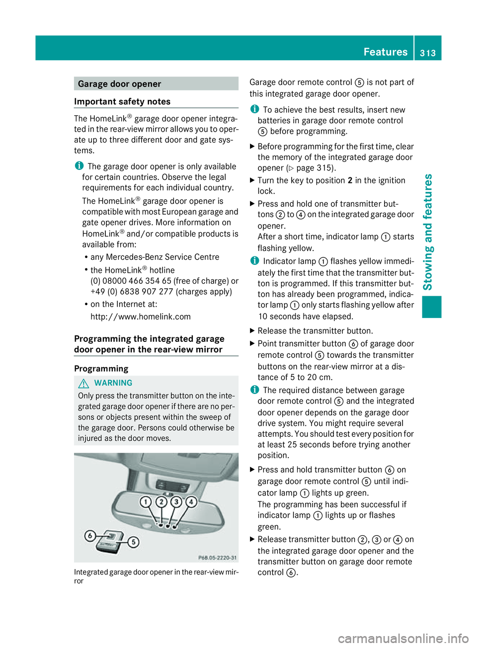
injured as the door moves. Integrated garage door opener in the rear-view mir-
ror Garage door remote control
Ais not part of
this integrated garage door opener.
i To achieve the best results, insert new
batteries in garage door remote control
A before programming.
X Before programming for the first time, clear
the memor yofthe integrated garage door
opener (Y page 315).
X Tur nthe key to position 2in the ignition
lock.
X Press and hold one of transmitter but-
tons ;to? on the integrated garage door
opener.
Af teras hort time, indicator lamp :star ts
fl ashing yellow.
i Indicator lamp :flashes yellow immedi-
ately the first time that the transmitter but-
ton is programmed. If this transmitter but-
ton has already been programmed, indica-
tor lamp :only start sflashing yellow after
10 seconds have elapsed.
X Release the transmitter button.
X Point transmitter button Bof garage door
remote control Atowards the transmitter
button sonthe rear-vie wmirror at adis-
tanc eof5 to 20 cm.
i The required distance between garage
door remote control Aand the integrated
door opener depends on the garage door
driv esystem. You might require several
attempts. You should test every position for
at leas t25seconds befor etryin ganother
position.
X Pres sand hol dtransmitter button Bon
garag edoor remote con trol A until indi-
cator lamp :lights up green.
The programmin ghas been successful if
indicator lamp :lights up or flashes
green.
X Release transmitter button ;,=or? on
the integrated garage door opener and the
transmitter button on garage door remote
control B. Features
313Stowingandfeatures Z
Page 317 of 389
If indicato
rlamp :lights up red:
X Repeat the programming procedure for the
transmitter buttons. When doing so, vary
the distance betwee nthe garage door drive
remote con troland the rear-view mirror.
i If the indicator lamp flashes gree nafter
successfu lprogramming, th egarage door
system is using arollin gcode. Af terp ro-
gramming ,you must synchronise the
garage door opener integrated in the rear-
view mirror with the receive rofthe garage
door system.
Synchronising th erolling code
Your vehicle must be within reach of the
garage or gate opener drive. Make sure that
neither your vehicle nor any persons/objects
are present within the sweep of the door or
gate.
Observe the safety notes when performing
the rolling code synchronisation.
X Turn the key to position 2in the ignition
lock.
X Press the programming button of the door
or gate drive (see the door or gate drive
operating instructions, e.g. under "Pro-
gramming of additional remote controls").
i Usually, you now have 30 seconds to ini-
tiate the next step.
X Press the previously programmed button of
the integrated HomeLink ®
garage door
opener repeatedly until the door starts to
move.
The rolling code synchronisation is then
complete.
Problems when programming
If you have problems when programming the
integrated garage door opener, please note
the following:
R check the transmitter frequency of garage
door remote control A(this can usually be
found on the rear of the remote control).
R change the batteries in garage door remote
control A.This increases the likelihood that garage door remote con
trolAwill
send astron gand precis esignal to the
integrated remote control in the rear-view
mirror.
R when programming, hold garage door
remote control Aat different distances
and angles from the transmitter button that
you are programming. Try various angles at
ad istance of between 5and 30 cm or the
same angle but varying distances.
R if there is another remote control for the
same garage doo rdrive ,perform the pro-
grammin gsteps again using this remote
control. Before performing thes esteps,
make sure that new batterie shave been
fitted in the garage door drive remote con-
trol.
R note that some remote controls transmit
only for alimited period (the indicator lamp
on the remote control goes out). Press the
button on the remote control again before
transmission ends.
R align the aerial cable of the garage door
opener unit. This can improv esignal recep-
tion/transmission.
Opening or closing the garage door Once programmed, the integrated garage
door opener will assume the func
tion of the
garage door system's remote con trol. Please
also read the operating instruc tions for the
garage door system.
X Tur nthe key to position 2in the ignition
lock.
X Press overhead con trolpanel transmitter
button ;,=or? that you have pro-
grammed to operate the garage door.
Garage door system with afixed code: indi-
cator lamp :lights up green.
Garage door system with arollin gcode:
indicator lamp :flashes green.
i The transmitter will transmit asignal for
as long as the transmitter button is
pressed. The transmission is halted after a
maximum of 10 seconds, and indicator 314
FeaturesStowin
gand features
Page 318 of 389
lamp
:flashes yellow. Press the transmit-
ter button again, if necessary.
Clearing th ememory of th eintegrated
garage door opene rint he rear-view mir-
ror X
Turn the key to position 2in the ignition
lock.
X Press transmitter buttons ;and ?.
The indicator lamp ligh tsup yellow.
X Press and hold transmitter buttons ;
and ?until the indicator lamp turns green.
i Make sure that you clear the memory of
the integrated garage door opener before
selli ngthe vehicle. Features
315Stowingand fe atures Z
Page 319 of 389
Frequencies for th
egarage doo ropener Th
er adio typ eapproval number and th efrequency range for th egarag edoor opener can be
fou ndonthe Interne tat: http://www.mercedes-benz.de/betriebsanleitung. Floormats
G
WARNING
Make sure that there is sufficient clearance
around the pedals when floormats are used,
and that the floormats are properly secured.
The floormats must be correctly secured at all
times using retainer sand press-studs.
Before you drive off ,chec kthe floormats and
secur eifnecessary. Afloormat which is not
properly secured can slip and, thereby, inter-
fere with the movemen tofthe pedals.
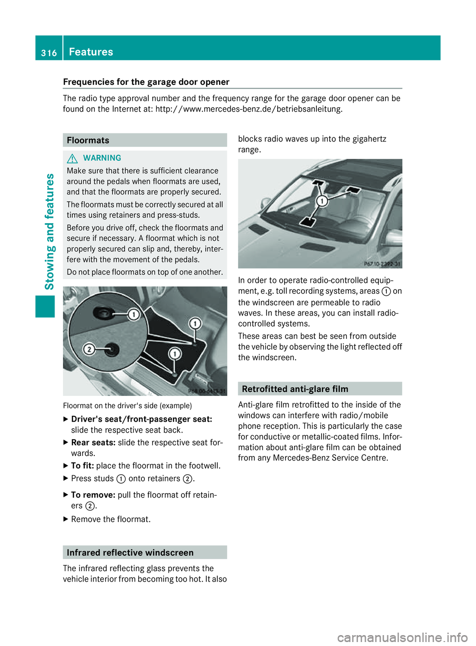
Do not plac efloormats on top of one another. Floormat on the driver's side (example)
X
Driver's seat/front-passenger seat:
slide the respective seat back.
X Rear seats: slide the respective seat for-
wards.
X To fit: place the floorma tinthe footwell.
X Press studs :ontoretainers ;.
X To remove: pull the floormat off retain-
ers ;.
X Remov ethe floormat. Infrared reflective windscreen
The infrared reflecting glass prevents the
vehicle interior from becoming too hot. It also blocks radio waves up int
othe gigahertz
range. In orde
rtooperateradio-controlled equip-
ment, e.g. toll recording systems, areas :on
the windscreen are permeable to radio
waves. In these areas, you can install radio-
controlled systems.
Thes earea scan best be seen from outside
the vehicle by observing the light reflected off
the windscreen. Retrofitted anti-glar
efilm
Anti-glar efilm retrofitted to the inside of the
windows can interfer ewith radio/mobile
phone reception. This is particularly the case
for conductive or metallic-coated films. Infor-
mation about anti-glar efilm can be obtained
from any Mercedes-Ben zService Centre. 316
FeaturesStowing and features
Page 320 of 389
Usefu
linfor mation ............................ 318
Engine compartment ........................318
Maintenance ...................................... 322
Care .................................................... 324 317Maint
enance andcare