MERCEDES-BENZ METRIS 2020 MY20 Operator’s Manual
Manufacturer: MERCEDES-BENZ, Model Year: 2020, Model line: METRIS, Model: MERCEDES-BENZ METRIS 2020Pages: 320, PDF Size: 26.38 MB
Page 171 of 320
Ensure that the following weights are not
exceeded:
R the permissible noseweight
R the permissible trailer load
R the permissible rear axle load of the towing
vehicle
R the maximum permissible gross vehicle
weight of both the towing vehicle and the
trailer
R the maximum permissible gross weight of
vehicle/trailer combination
The applicable permissible values that may not
be exceeded can be found:
R in your vehicle documents
R on the type plates for the trailer tow hitch
R on the type plates for the trailer
R on the vehicle identification plate
(Y page
304)
Where the values differ, the lowest is valid.
You will find the values approved by the manu-
facturer on the vehicle identification plates
and those for the towing vehicle in the "Tech-
nical data" section (Y page 315).
Your vehicle behaves differently with a trailer
than without one.
The vehicle/trailer combination:
R is heavier
R is restricted in its acceleration and gradient-
climbing capability
R has an increased braking distance
R is more susceptible to strong crosswinds
R requires more sensitive steering
R has a larger turning radius
This may impair the handling characteristics.
When towing a trailer, always adjust your
speed to suit the road and weather conditions.
Drive carefully. Maintain a safe distance.
If you require any further explanation regard-
ing the information contained in the Operating
Instructions, please contact a Mercedes-Benz
Commercial Van Center.
General notes R
Observe the legally permitted maximum
speed for vehicle/trailer combinations in
the relevant country, state or Canadian
province. Before beginning the journey,
check the trailer's documents for the maxi-
mum permitted speed of your trailer. This reduces the risk of accidents.
R Install only an approved trailer coupling on
your vehicle. Only use a ball coupling for
your Metris trailer tow hitch if it has been
approved for your vehicle. More information
on the availability, mounting and installation
of the trailer electrics is available at any
qualified specialist workshop.
R The trailer coupling is one of the most
important vehicle parts with regard to road
safety. Observe the notes on operation, care
and maintenance of the trailer tow hitch
(see the manufacturer's operating instruc-
tions).
R The bumpers of your vehicle are not suitable
for installing detachable trailer couplings.
R Do not attach rented trailer tow hitches or
other detachable trailer tow hitches to the
bumper.
R Minimize the risk of damage to the ball cou-
pling. If you do not require the ball coupling,
remove it from the ball coupling recess.
You will find weight information under "Techni-
cal data"
(Y page 315).
The height of the ball neck changes according
to the load on the vehicle. If this is case, use a
trailer with a height-adjustable trailer drawbar.
Driving tips The maximum permissible speed for vehicle/
trailer combination depends on the type of
trailer. Before beginning the journey, check
the trailer's documents for the maximum per-
mitted speed of your trailer. Observe the
legally permitted maximum speed in the rele-
vant country, state or Canadian province.
When towing a trailer, your vehicle's handling
characteristics will be different in comparison
to when driving without a trailer and it will con-
sume more fuel.
On long and steep downhill gradients, select a
lower gear.
i This also applies if cruise control is activa-
ted.
This enables you to utilize the engine's braking
effect and you do not need to brake so heavily
to keep the correct speed. This relieves the
load on the brake system and prevents the
brakes from overheating and wearing too
quickly. If you need to brake additionally, to Towing a trailer
169
Driving and parking Z
Page 172 of 320
not depress the brake pedal constantly, but
periodically.
Observe the notes on ESP
®
trailer stabilization
( Y page
69).
Driving tips If the trailer begins to swing from side to side:
X Do not accelerate.
X Do not counter-steer.
X Brake if necessary.
i You can reduce the risk of the trailer
swinging and rocking by retrofitting anti-roll
bars or trailer stability programs. Further
information is available at your authorized
Mercedes-Benz Van Dealer.
R Maintain a greater distance than you would
when driving without towing a trailer.
R Avoid sudden braking. Apply the brakes gen-
tly at first to allow the trailer brake to over-
run. Then, increase the brake force quickly.
R The figures for the gradient climbing capa-
bilities from a standstill refer to sea level.
When driving in mountainous areas, note
that the power output of the engine, and
with it its gradient climbing capability,
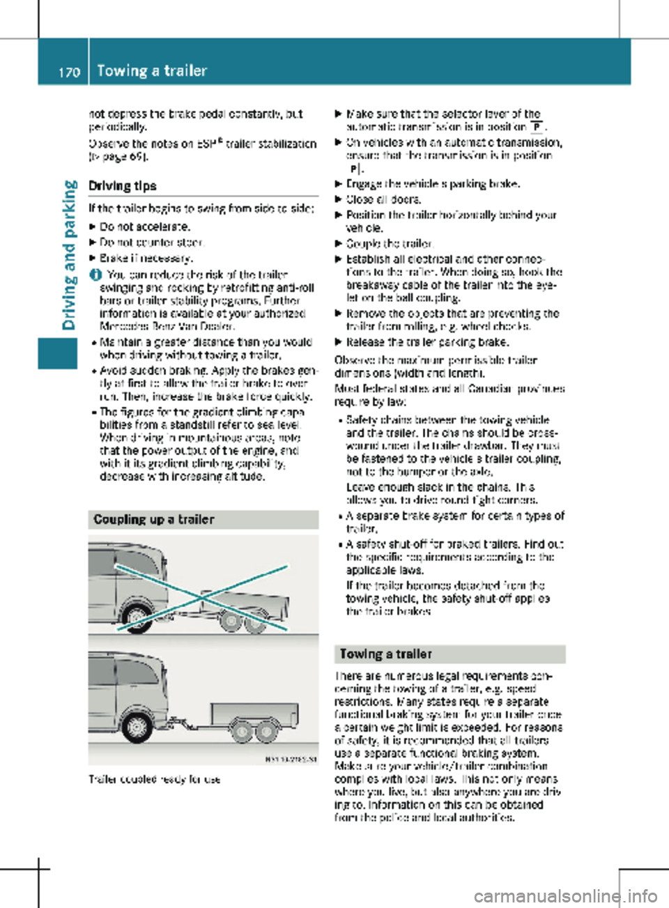
decrease with increasing altitude. Coupling up a trailer
Trailer coupled ready for use X
Make sure that the selector lever of the
automatic transmission is in position j.
X On vehicles with an automatic transmission,
ensure that the transmission is in position
j.
X Engage the vehicle's parking brake.
X Close all doors.
X Position the trailer horizontally behind your
vehicle.
X Couple the trailer.
X Establish all electrical and other connec-
tions to the trailer. When doing so, hook the
breakaway cable of the trailer into the eye-
let on the ball coupling.
X Remove the objects that are preventing the
trailer from rolling, e.g. wheel chocks.
X Release the trailer parking brake.
Observe the maximum permissible trailer
dimensions (width and length).
Most federal states and all Canadian provinces
require by law: R Safety chains between the towing vehicle
and the trailer. The chains should be cross-
wound under the trailer drawbar. They must
be fastened to the vehicle's trailer coupling,
not to the bumper or the axle.
Leave enough slack in the chains. This
allows you to drive round tight corners.
R A separate brake system for certain types of
trailer.
R A safety shut-off for braked trailers. Find out
the specific requirements according to the
applicable laws.
If the trailer becomes detached from the
towing vehicle, the safety shut-off applies
the trailer brakes. Towing a trailer
There are numerous legal requirements con-
cerning the towing of a trailer, e.g. speed
restrictions. Many states require a separate
functional braking system for your trailer once
a certain weight limit is exceeded. For reasons
of safety, it is recommended that all trailers
use a separate functional braking system.
Make sure your vehicle/trailer combination
complies with local laws. This not only means
where you live, but also anywhere you are driv-
ing to. Information on this can be obtained
from the police and local authorities. 170
Towing a trailer
Driving and parking
Page 173 of 320
Observe the following when towing a trailer:
R Practice driving around bends, stopping and
backing up at a place where there is no traf-
fic. This enables you to gain experience and
get used to the new handling characteris-
tics.
R Before driving, check:
- that the trailer tow hitch and ball coupling
are secure
- that the safety switch for a braked trailer
is functioning properly
- that the safety chains are secure and not
damaged
- that the electrical connections are secure
- that the lights are working
- that the wheels are in good order and the
tire pressure is correct
R Adjust the exterior mirrors to provide an
unobstructed view of the rear section of the
trailer.
R If the trailer is equipped with a separate
functional braking system, check before
each journey whether the brakes are func-
tioning correctly.
R Secure the load on the trailer according to
the applicable specifications and current
standards on securing loads
(Y page 244).
R When driving with a trailer, check at regular
intervals that the load is secured and that
the brakes and lights are working.
R Bear in mind that the handling will be less
stable when towing a trailer than when driv-
ing without one. Avoid sudden steering
movements.
R The vehicle/trailer combination is heavier,
accelerates more slowly and has a
decreased gradient climbing capability and a
longer braking distance.
It is more susceptible to crosswinds and
requires cautious steering.
R If possible, do not brake suddenly, but
rather moderately at first so that the trailer
can activate its brakes. Then increase the
force on the brake pedal.
R If the automatic transmission repeatedly
shifts between gears when driving on
inclines, restrict the shift range. Select shift
range 4, 3, 2 or 1.
Driving in a low gear and at a low speed
reduces the risk of damaging the engine. R
When driving on a downhill gradient, shift to
a low gear and take advantage of the
engine's braking effect.
Avoid continuous brake application as this
may overheat the vehicle brakes and, if
installed, the trailer brakes.
R If the coolant temperature increases dra-
matically while the air-conditioning system
is switched on, switch off the air-condition-
ing system.
Coolant heat can also be dissipated by
switching the airflow and the temperature of
the air conditioning to the maximum level.
Open the windows if necessary.
R When overtaking, pay particular attention to
the extended length of your vehicle/trailer
combination.
Due to the length of your vehicle/trailer
combination you need an additional dis-
tance before you can return to your original
lane. Uncoupling a trailer
G
WARNING
If you uncouple a trailer with the overrun
brake engaged, you could trap your hand
between the vehicle and the trailer drawbar.
There is a risk of injury.
Do not uncouple a trailer if the overrun
brake is engaged.
! Do not disconnect a trailer with an
engaged overrun brake. Otherwise, your
vehicle could be damaged by the rebound-
ing of the overrun brake.
X Make sure that the selector lever of the
automatic transmission is in position P.
X Engage the vehicle's parking brake.
X Close all doors.
X Apply the parking brake of the trailer.
X In addition, secure the trailer against rolling
away with a wheel chock or similar object.
X Remove the trailer cable and safety chains
and decouple the trailer. Towing a trailer
171
Driving and parking Z
Page 174 of 320
Permissible trailer loads and trailer
drawbar noseweights
Weight information !
For vehicles with a permissible gross vehi-
cle weight of 6614 lbs (3000 kg), the per-
missible gross combination mass is less
than the sum of the permissible gross vehi-
cle weight plus the permissible trailer load.
Exceeding the permissible gross combina-
tion mass can lead to damage to the drive-
train, to the transmission or to the trailer
hitch.
If either the vehicle or the trailer is fully
laden, the permitted gross vehicle weight or
the permitted trailer load values are reduced
accordingly. In this case, you may only parti-
ally load the trailer or the vehicle.
The gross trailer weight (GTW) is calculated by
adding the weight of the trailer to the weight
of the load and equipment. If the trailer is
installed with a separate functional braking
system, then the maximum gross trailer weight
is 5000 lbs (2268 kg). G
WARNING
If you tow a trailer without a separate func-
tional braking system and a gross trailer
weight (GTW) of more than
1635 lbs
(750 kg), then the vehicle brake system may
overheat. This increases the braking dis-
tance and the brake system may even fail.
There is an increased risk of accident and
injury, possibly even fatal.
Always use a trailer with a separate func-
tional braking system when towing a trailer
with a gross trailer weight (GTW) of more
than 1635 lbs (750 kg).
The maximum noseweight of the trailer draw-
bar on the ball coupling is 500 lbs (227 kg).
The actual noseweight may not exceed the
value given on the identification plates of the
trailer tow hitch or the trailer. If the values
vary, the lowest value always applies.
The gross combination weight rating (GCWR) is
calculated by adding the gross weight of the
trailer to the gross vehicle weight including a
driver's weight of approximately 150 lbs
(68 kg). The permissible Gross Combination Weight Rating is vehicle-specific and depends
on the equipment level.
When driving with a trailer, you should not
exceed the permitted Gross Combination
Weight Rating (GCWR).
The permissible values, which must not be
exceeded, can be found in your vehicle docu-
ments and on the trailer tow hitch type plates
for the trailer and the vehicle (
Y page
304).
The basic values approved by the manufac-
turer can also be found in the "Technical data"
section ( Y page 315). If the values vary, the
lowest value always applies.
Loading a trailer !
Utilize the maximum permissible nose-
weight as fully as possible. Do not allow the
weight to fall below the minimum permissi-
ble noseweight, otherwise the trailer may
come loose.
R The load must be distributed over the vehi-
cle and the trailer so as not to exceed either
the maximum permissible values for the
gross vehicle weight rating (GVWR) and
gross trailer weight (GTW), the gross combi-
nation weight rating (GCWR), nor the maxi-
mum permissible gross axle weight rating
(GAWR) and trailer drawbar noseweight rat-
ing of your vehicle.
R Add the drawbar noseweight on the ball
coupling (TWR) to the rear axle load. This
will prevent you from exceeding the permis-
sible gross axle weight (GAWR).
R Add the drawbar noseweight on the ball
coupling (TWR) to the vehicle payload. This
will ensure that you do not exceed the per-
missible gross vehicle weight rating (GVWR).
Checking the vehicle and trailer
weight R
Make sure the weights of the towing vehicle
and the trailer comply with the maximum
permissible values. Have the vehicle/trailer
combination weighed on a calibrated weigh-
bridge. The vehicle/trailer combination con-
sists of the towing vehicle including the
driver, passengers and load, as well as the
loaded trailer.
R Check the maximum permissible gross axle
weight rating of the front and rear axles
(GAWR), the gross trailer weight (GTW), the
gross combination weight rating (GCWR) 172
Towing a trailer
Driving and parking
Page 175 of 320
and the noseweight of the trailer drawbar
(TWR).
Trailer power supply
! Incorrect wiring of the connector plug
could, under certain circumstances, cause
malfunctions in the vehicle's other elec-
tronic systems. We therefore recommend
having the connector plug wired at a quali-
fied specialist workshop.
! You can connect accessories with a maxi-
mum power consumption of 240 W
to the
permanent power supply.
You must not charge a trailer battery using
the power supply.
Your vehicle may be equipped with various
electrical installations for trailer towing.
Depending on your trailer, you may need an
adapter to connect the electrical system of the
trailer with that of the vehicle.
The trailer socket of your vehicle is equipped
at the factory with a permanent power supply.
The permanent power supply is on the trailer
socket pin assignment 4.
Note that the permanent power supply of the
trailer is not switched off when the on-board
voltage is low. This can completely discharge
the starter battery of your vehicle.
Further information on the electrical equip-
ment currently installed on your vehicle and on
installing trailer electrics can be obtained at
any qualified specialist workshop. Towing a trailer
173
Driving and parking Z
Page 176 of 320
Useful information
This Operator's Manual describes all models
as well as standard and optional equipment of
your vehicle that were available at the time of
going to print. Country-specific variations are
possible. Note that your vehicle may not be
equipped with all of the described functions.
This also applies to systems and functions rel-
evant to safety.
Read the information on qualified specialist
workshops (Y page
32).Important safety notes
G
WARNING
If you operate information systems and com-
munication equipment integrated in the
vehicle when driving, you may be distracted
from the traffic situation. You could also
lose control of the vehicle. There is a risk of
an accident.
Only operate this equipment when the traffic
situation permits. If you are not sure that
this is possible, park the vehicle paying
attention to traffic conditions and operate
the equipment when the vehicle is station-
ary. G
WARNING
If you are driving and reach through the
steering wheel to operate the adjustment
knob, you could lose control of the vehicle.
There is a risk of an accident and injury.
Only operate the adjustment knobs when
the vehicle is stationary. Do not reach
through the steering wheel when driving.
You must observe the legal requirements for
the country in which you are currently driving
when operating the on-board computer. G
WARNING
If the instrument cluster has failed or mal-
functioned, you may not recognize function
restrictions in systems relevant to safety. The operating safety of your vehicle may be
impaired. There is a risk of an accident.
Drive on carefully. Have the vehicle checked
at a qualified specialist workshop immedi-
ately.
The on-board computer display only shows
messages and warnings from certain systems.
You should therefore make sure your vehicle is
operating safely at all times. If the operating
safety of your vehicle is impaired, stop the
vehicle as soon as possible, paying attention
to road and traffic conditions. Then consult a
qualified specialist workshop.
The accuracy of the speedometer and odome-
ter displays is legally prescribed. Determining
the speed is dependent on the wheel size or
the rolling circumference of the wheels. If you
change the wheel size on your vehicle, make
sure it is assigned to the correct wheel size
category ( Y page
278). If you change wheel
size category without recoding the control
unit, the speedometer indication will be inac-
curate. Driving safety and driving systems may
be impaired or detect a malfunction and shut
down.
An overview of the instrument cluster can be
found under "Instrument cluster":
R for vehicles without steering wheel buttons
(Y page 38)
R for vehicles with steering wheel buttons
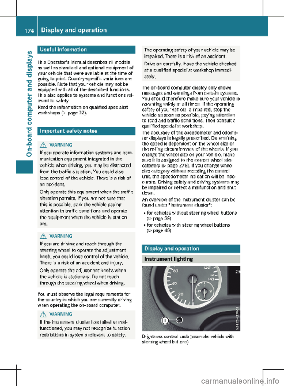
(Y page 40) Display and operation
Instrument lighting
Brightness control knob (example: vehicle with
steering wheel buttons)174
Display and operation
On-board computer and displays
Page 177 of 320

In daylight, the displays in the instrument clus-
ter are illuminated. A dimming function is not
possible in daylight.
On vehicles with steering wheel buttons, the
light sensor in the instrument cluster automat-
ically controls the brightness of the display
lighting.
While the lights are on, the brightness is
dependent upon the brightness of the ambient
light. You can also adjust the brightness of the
instrument lighting and the display lighting:
R by pressing the f and g buttons on the
instrument cluster on vehicles without
steering wheel buttons (not in the Settings
menu)
R by turning brightness control knob : on
vehicles with steering wheel buttons Speedometer
If you change the wheel size on your vehicle,
make sure it is assigned to the correct wheel
size category ( Y page
278). If you change
wheel size category without recoding the con-
trol unit, the speedometer indication will be
inaccurate. The current vehicle speed may
then be higher than the speed displayed in the
speedometer.
The speed can also be shown in the display in
the form of a digital speedometer:
R on vehicles without steering wheel buttons
(Y page 178)
R on vehicles with steering wheel buttons
(Y page 185)
i In some countries, a warning sounds
and/or the display shows a message when
the vehicle reaches the maximum legally
permissible speed limit, e.g. at 75 mph
(120 km/h). Tachometer
! Do not drive in the overrevving range, as
this could damage the engine. H
Environmental note
Avoid driving at high engine speeds. This
unnecessarily increases the fuel consump-
tion of your vehicle and harms the environ-
ment as a result of increased emissions. The red band in the tachometer indicates the
engine's overrevving range.
To protect the engine, the fuel supply is inter-
rupted when the red band is reached.
Outside temperature display
You should pay special attention to road con-
ditions when temperatures are around freezing
point.
Please bear in mind that the outside tempera-
ture display shows the air temperature meas-
ured and not the road temperature.
The display shows the outside temperature in
the header:
R on vehicles without steering wheel buttons
(Y page
176)
R on vehicles with steering wheel buttons
(Y page 183)
Changes in the outside temperature are dis-
played after a short delay. Coolant temperature gauge
G
WARNING
Opening the hood when the engine is over-
heated or when there is a fire in the engine
compartment could expose you to hot gases
or other service products. There is a risk of
injury.
Let an overheated engine cool down before
opening the hood. If there is a fire in the
engine compartment, keep the hood closed
and contact the fire department.
On vehicles without steering wheel buttons,
you can have the coolant temperature shown
in the display
(Y page 178).
On vehicles with steering wheel buttons, an
analog coolant temperature gauge is located
in the tachometer in the instrument cluster
(Y page 40). Under normal driving conditions and at the
correct coolant level, the display may rise to
the letter H or to the red mark. Display and operation
175
On-board computer and displays Z
Page 178 of 320
On-board computer (vehicles with-
out steering wheel buttons)
Operating the on-board computer
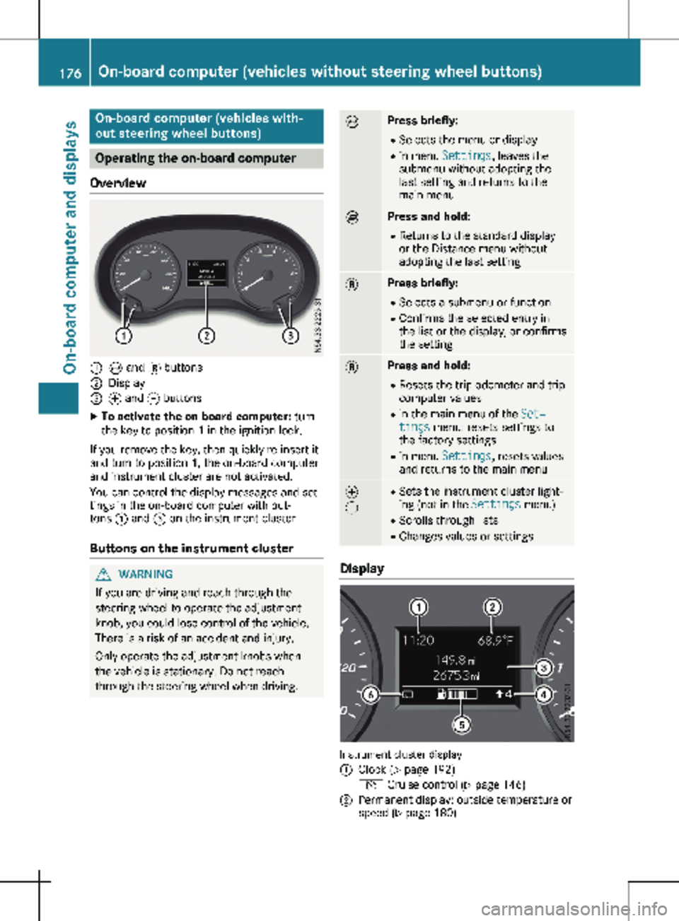
Overview :
È and 3 buttons
; Display
= f and g buttons
X To activate the on-board computer: turn
the key to position 1 in the ignition lock.
If you remove the key, then quickly re-insert it
and turn to position 1, the on-board computer
and instrument cluster are not activated.
You can control the display messages and set-
tings in the on-board computer with but-
tons : and = on the instrument cluster.
Buttons on the instrument cluster G
WARNING
If you are driving and reach through the
steering wheel to operate the adjustment
knob, you could lose control of the vehicle.
There is a risk of an accident and injury.
Only operate the adjustment knobs when
the vehicle is stationary. Do not reach
through the steering wheel when driving. È Press briefly:
R Selects the menu or display
R in menu Settings, leaves the
submenu without adopting the
last setting and returns to the
main menu È Press and hold:
R
Returns to the standard display
or the Distance menu without
adopting the last setting 3 Press briefly:
R Selects a submenu or function
R Confirms the selected entry in
the list or the display, or confirms
the setting 3 Press and hold:
R
Resets the trip odometer and trip
computer values
R in the main menu of the Set‐
tings menu: resets settings to
the factory settings
R in menu Settings, resets values
and returns to the main menu f
g R
Sets the instrument cluster light-
ing (not in the Settings menu)
R Scrolls through lists
R Changes values or settings Display
Instrument cluster display
:
Clock (Y page 192)
V Cruise control (Y page
146)
; Permanent display: outside temperature or
speed
(Y page 180)176
On-board computer (vehicles without steering wheel buttons)
On-board computer and displays
Page 179 of 320
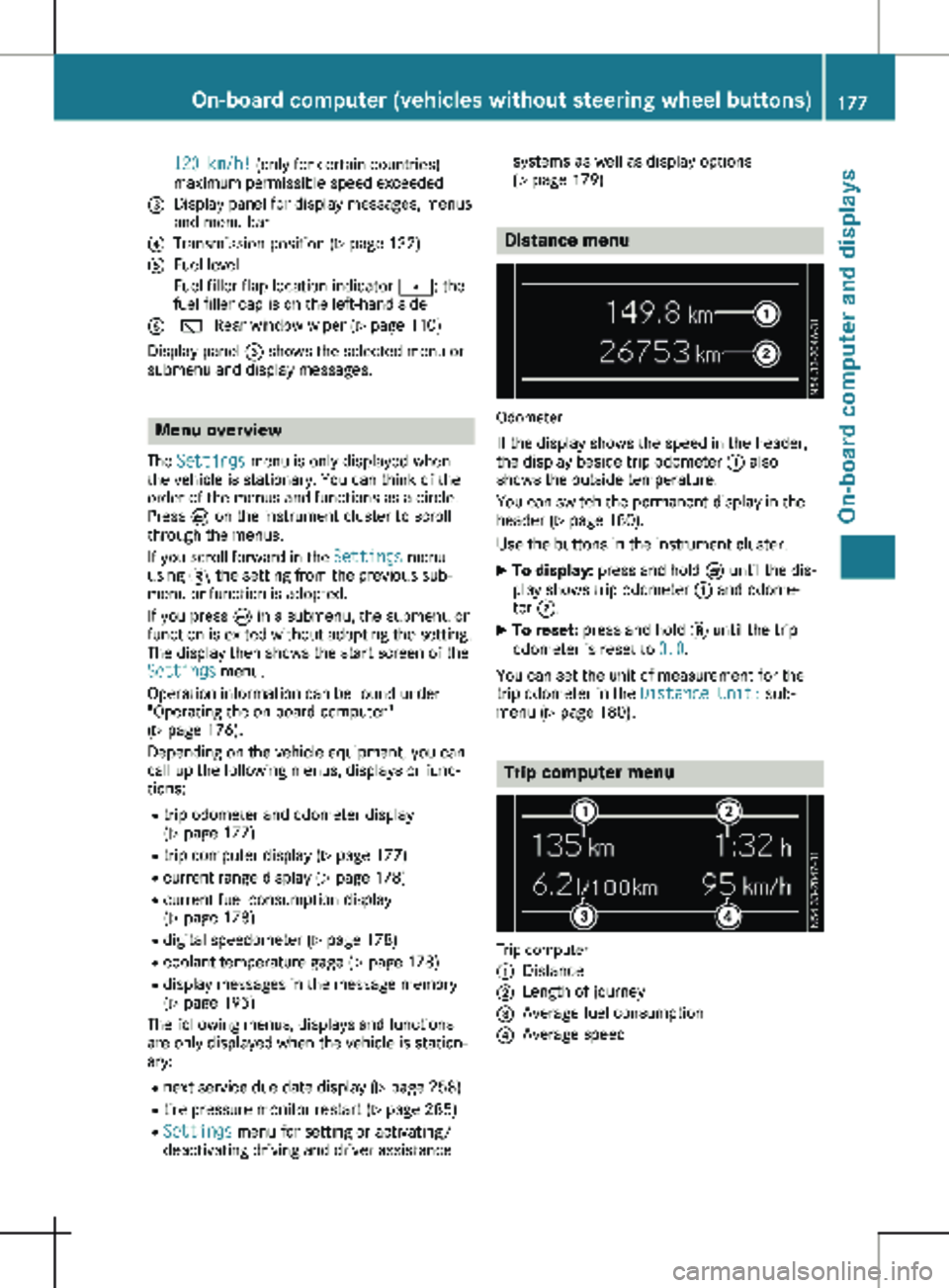
120 km/h! (only for certain countries)
maximum permissible speed exceeded
= Display panel for display messages, menus
and menu bar
? Transmission position (Y page 132)
A Fuel level
Fuel filler flap location indicator t: the
fuel filler cap is on the left-hand side
B è Rear window wiper
(Y page 110)
Display panel = shows the selected menu or
submenu and display messages. Menu overview
The Settings menu is only displayed when
the vehicle is stationary. You can think of the
order of the menus and functions as a circle.
Press È on the instrument cluster to scroll
through the menus.
If you scroll forward in the Settings menu
using 3, the setting from the previous sub-
menu or function is adopted.
If you press È in a submenu, the submenu or
function is exited without adopting the setting.
The display then shows the start screen of the
Settings menu.
Operation information can be found under
"Operating the on-board computer"
(Y page
176).
Depending on the vehicle equipment, you can
call up the following menus, displays or func-
tions:
R trip odometer and odometer display
(Y page 177)
R trip computer display (Y page 177)
R current range display (Y page 178)
R current fuel consumption display
(Y page 178)
R digital speedometer ( Y page 178)
R coolant temperature gage (Y page 178)
R display messages in the message memory
(Y page 195)
The following menus, displays and functions
are only displayed when the vehicle is station-
ary:
R next service due date display ( Y page 258)
R tire pressure monitor restart (Y page 285)
R Settings menu for setting or activating/
deactivating driving and driver assistance systems as well as display options
(Y page
179) Distance menu
Odometer
If the display shows the speed in the header,
the display beside trip odometer : also
shows the outside temperature.
You can switch the permanent display in the
header
(Y page 180).
Use the buttons in the instrument cluster.
X To display: press and hold È until the dis-
play shows trip odometer : and odome-
ter ;.
X To reset: press and hold 3 until the trip
odometer is reset to 0.0.
You can set the unit of measurement for the
trip odometer in the Distance Unit: sub-
menu (Y page
180). Trip computer menu
Trip computer
:
Distance
; Length of journey
= Average fuel consumption
? Average speed On-board computer (vehicles without steering wheel buttons)
177
On-board computer and displays Z
Page 180 of 320
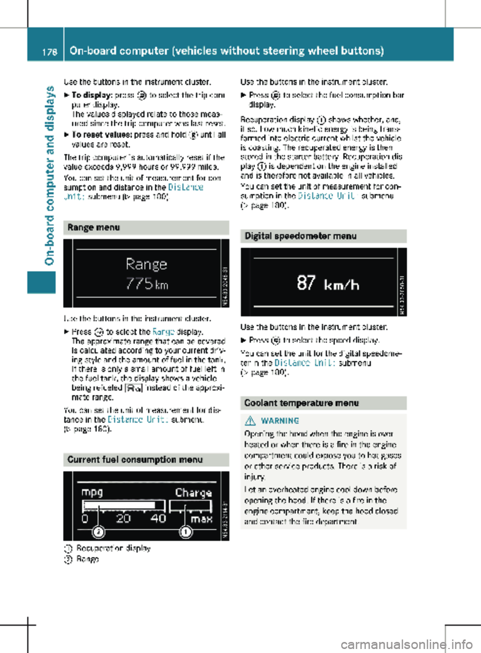
Use the buttons in the instrument cluster.
X To display: press È to select the trip com-
puter display.
The values displayed relate to those meas-
ured since the trip computer was last reset.
X To reset values: press and hold 3 until all
values are reset.
The trip computer is automatically reset if the
value exceeds 9,999 hours or 99,999 miles.
You can set the unit of measurement for con-
sumption and distance in the Distance
Unit: submenu ( Y page 180).Range menu
Use the buttons in the instrument cluster.
X Press È to select the Range display.
The approximate range that can be covered
is calculated according to your current driv-
ing style and the amount of fuel in the tank.
If there is only a small amount of fuel left in
the fuel tank, the display shows a vehicle
being refueled Ï instead of the approxi-
mate range.
You can set the unit of measurement for dis-
tance in the Distance Unit: submenu
(Y page
180). Current fuel consumption menu
:
Recuperation display
; Range Use the buttons in the instrument cluster.
X Press È to select the fuel consumption bar
display.
Recuperation display : shows whether, and,
if so, how much kinetic energy is being trans-
formed into electric current whilst the vehicle
is coasting. The recuperated energy is then
stored in the starter battery. Recuperation dis-
play : is dependent on the engine installed
and is therefore not available in all vehicles.
You can set the unit of measurement for con-
sumption in the Distance Unit: submenu
(Y page
180). Digital speedometer menu
Use the buttons in the instrument cluster.
X Press È to select the speed display.
You can set the unit for the digital speedome-
ter in the Distance Unit: submenu
(Y page
180). Coolant temperature menu
G
WARNING
Opening the hood when the engine is over-
heated or when there is a fire in the engine
compartment could expose you to hot gases
or other service products. There is a risk of
injury.
Let an overheated engine cool down before
opening the hood. If there is a fire in the
engine compartment, keep the hood closed
and contact the fire department. 178
On-board computer (vehicles without steering wheel buttons)
On-board computer and displays