air condition MERCEDES-BENZ ML320 1997 Complete Repair Manual
[x] Cancel search | Manufacturer: MERCEDES-BENZ, Model Year: 1997, Model line: ML320, Model: MERCEDES-BENZ ML320 1997Pages: 4133, PDF Size: 88.89 MB
Page 3317 of 4133
Blending air flap actuator
Recirculated air flap actuator motor
Electric heater booster (for engine 612.963 only) and therefore forms a complete unit.
The evaporator housing distributes the air that is required to ventilate the vehicle to the relevant air ducts and
vents depending on the required interior temperature.
The air ducting depends on various operating conditions such as:
Heating mode
Cooling mode
Blend air mode (cold/warm)
Cooling air mode with recirculated air
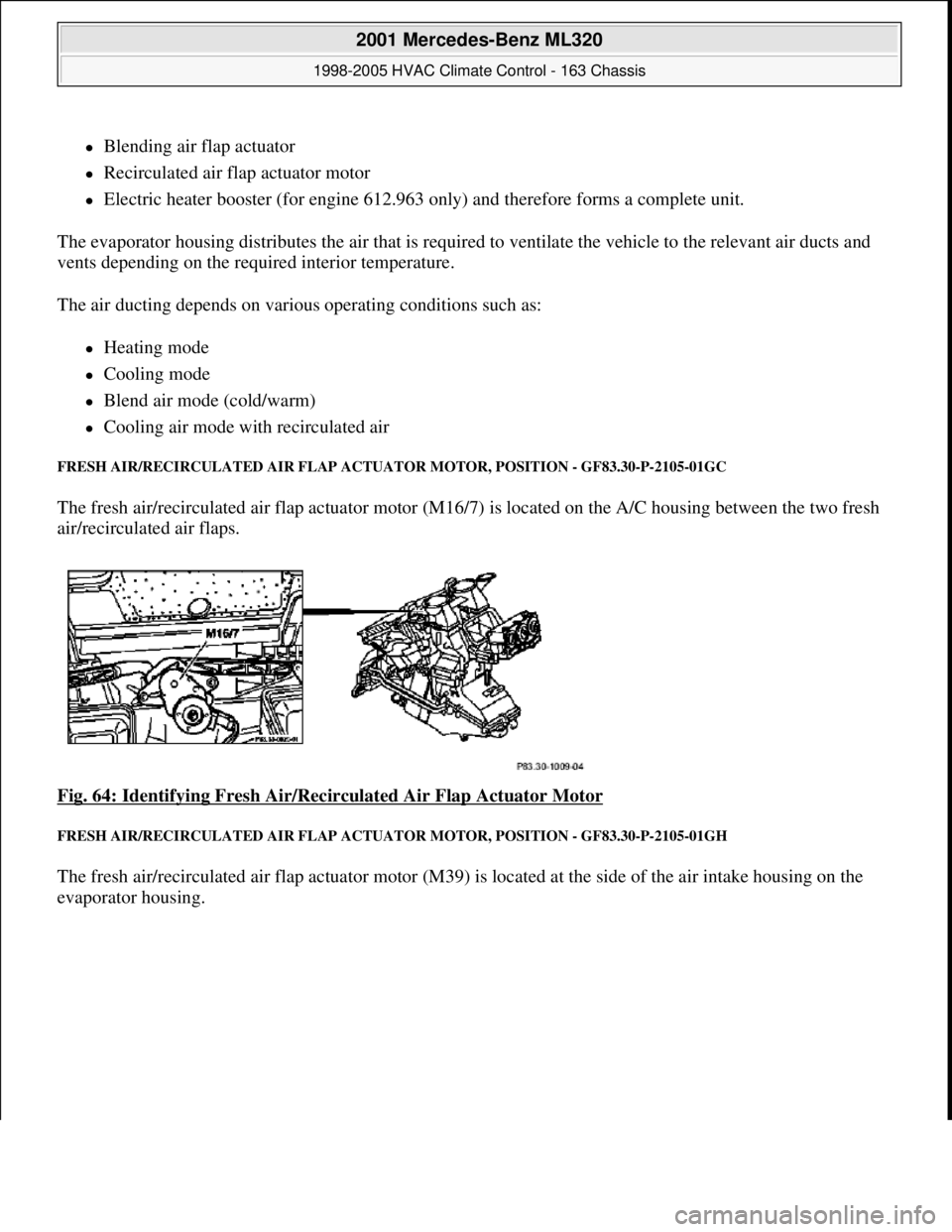
FRESH AIR/RECIRCULATED AIR FLAP ACTUATOR MOTOR, POSITION - GF83.30-P-2105-01GC
The fresh air/recirculated air flap actuator motor (M16/7) is located on the A/C housing between the two fresh
air/recirculated air flaps.
Fig. 64: Identifying Fresh Air/Recirculated Air Flap Actuator Motor
FRESH AIR/RECIRCULATED AIR FLAP ACTUATOR MOTOR, POSITION - GF83.30-P-2105-01GH
The fresh air/recirculated air flap actuator motor (M39) is located at the side of the air intake housing on the
evaporator housin
g.
2001 Mercedes-Benz ML320
1998-2005 HVAC Climate Control - 163 Chassis
me
Saturday, October 02, 2010 3:23:15 PMPage 73 © 2006 Mitchell Repair Information Company, LLC.
Page 3318 of 4133
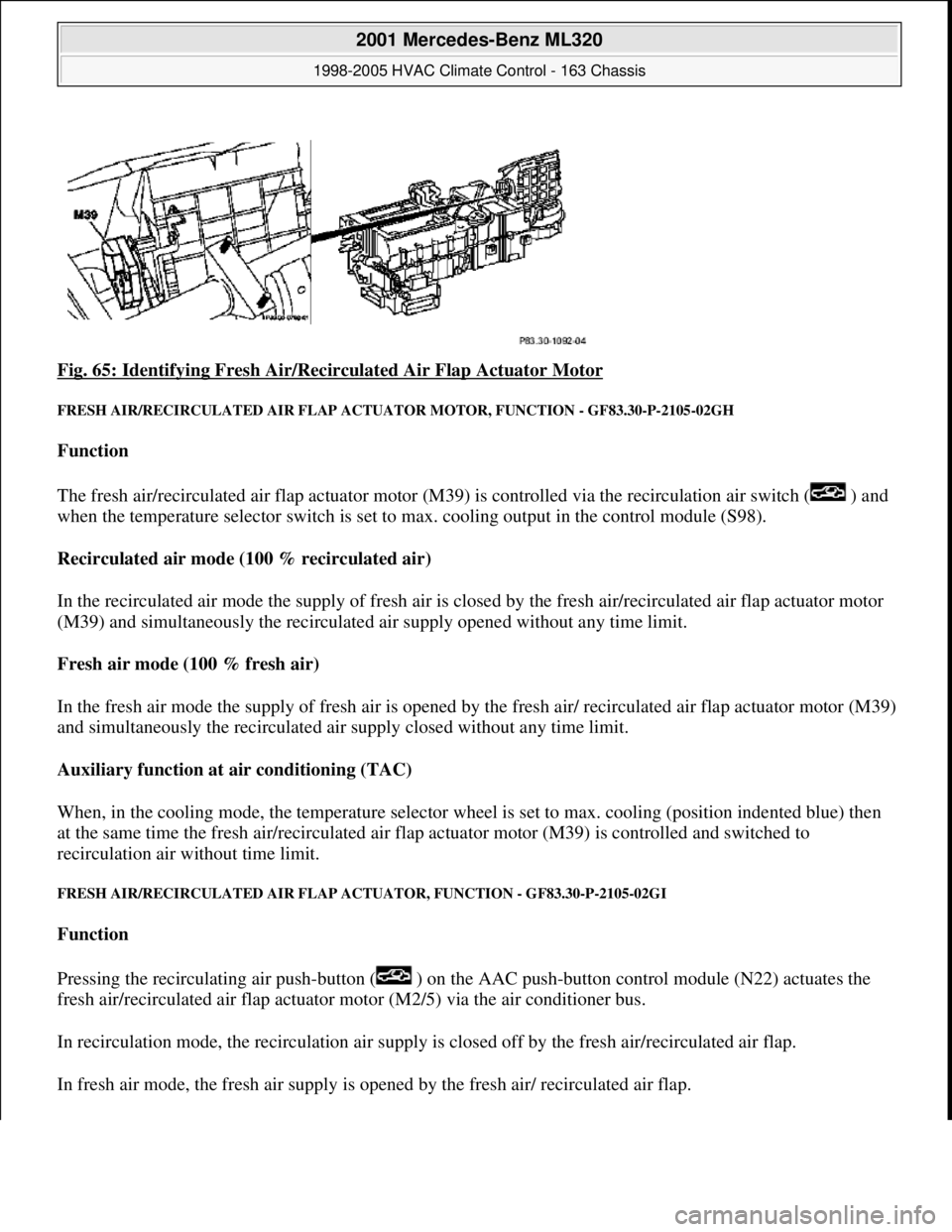
Fig. 65: Identifying Fresh Air/Recirc ulated Air Flap Actuator Motor
FRESH AIR/RECIRCULATED AIR FLAP ACTUATOR MOTO R, FUNCTION - GF83.30-P-2105-02GH
Function
The fresh air/recirculated air flap actuator motor (M39) is controlled via the recirculation air switch ( ) and
when the temperature selector switch is set to max. cooling output in the control module (S98).
Recirculated air mode (100 % recirculated air)
In the recirculated air mode the supply of fresh air is closed by the fresh air/recirculated air flap actuator motor
(M39) and simultaneously the recirculated air supply opened without any time limit.
Fresh air mode (100 % fresh air)
In the fresh air mode the supply of fresh air is opened by th e fresh air/ recirculated air flap actuator motor (M39)
and simultaneously the recirculated air supply closed without any time limit.
Auxiliary function at air conditioning (TAC)
When, in the cooling mode, the temperat ure selector wheel is set to max. cooling (position indented blue) then
at the same time the fres h air/recirculated air flap actuator moto r (M39) is controlled and switched to
recirculation air wi thout time limit.
FRESH AIR/RECIRCUL ATED AIR FLAP ACTUATOR, FU NCTION - GF83.30-P-2105-02GI
Function
Pressing the recirculating air push- button ( ) on the AAC push-button control module (N22) actuates the
fresh air/recirculated air flap actuator motor (M2/5) via the air conditioner bus.
In recirculation mode, the recircul ation air supply is closed off by th e fresh air/recirculated air flap.
In fresh air mode, the fresh air supply is ope ned by the fresh air/ recirculated air flap.
2001 Mercedes-Benz ML320
1998-2005 HVAC Climate Control - 163 Chassis
me
Saturday, October 02, 2010 3:23:15 PMPage 74 © 2006 Mitchell Repair Information Company, LLC.
Page 3319 of 4133
Control of fresh air/recirculated air flap via the AAC push-button control module (N22)
When the recirculating air push-button is pressed ( ) on the AAC push-button control module the system is
switched by means of the fresh air/recirculated air flap actuator motor straight to 100 % recirculation air. This is
displayed by the function LED.
If a problem exists, it is possible to retrieve and verify the defined end positions by means of the diagnosis
assistant system (DAS) (valuation trip).
After replacement of an actuator motor it is necessary for an adjustment run to be performed using the diagnosis
assistant system (DAS), i.e. the end positions flap OPEN and SHUT are defined and retained.
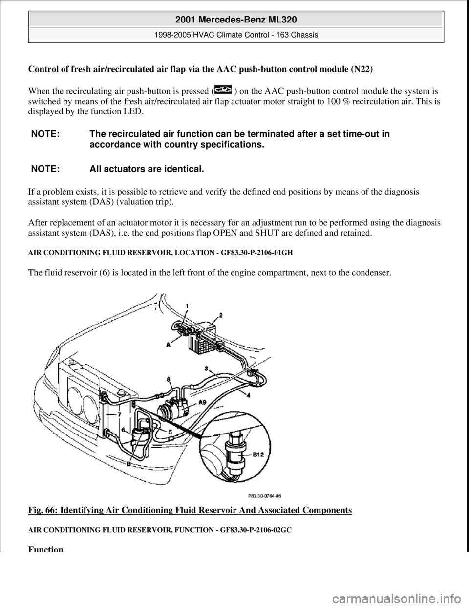
AIR CONDITIONING FLUID RESERVOIR, LOCATION - GF83.30-P-2106-01GH
The fluid reservoir (6) is located in the left front of the engine compartment, next to the condenser.
Fig. 66: Identifying Air Conditioning Fluid Reservoir And Associated Components
AIR CONDITIONING FLUID RESERVOIR, FUNCTION - GF83.30-P-2106-02GC
Function
NOTE: The recirculated air function can be terminated after a set time-out in
accordance with country specifications.
NOTE: All actuators are identical.
2001 Mercedes-Benz ML320
1998-2005 HVAC Climate Control - 163 Chassis
me
Saturday, October 02, 2010 3:23:15 PMPage 75 © 2006 Mitchell Repair Information Company, LLC.
Page 3320 of 4133
The liquefied refrigerant is routed under pressure into the fluid reservoir and flows through a stainless steel
meshing to the filter block. The pores in the filter block are matched precisely to the refrigerant's molecular size.
Thus the refrigerant can flow through the filter block.
All other matter, primarily water, is held back by this molecular filter and deposited. The cleaned refrigerant
flows over a rising pipe to the expansion valve.
Whenever the system is opened, the fluid reservoir should be replaced because of the water which has
collected there in the meantime.
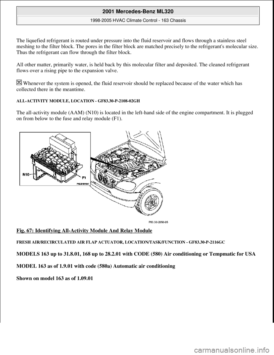
ALL-ACTIVITY MODULE, LOCATION - GF83.30-P-2108-02GH
The all-activity module (AAM) (N10) is located in the left-hand side of the engine compartment. It is plugged
on from below to the fuse and relay module (F1).
Fig. 67: Identifying All
-Activity Module And Relay Module
FRESH AIR/RECIRCULATED AIR FLAP ACTUATOR, LOCATION/TASK/FUNCTION - GF83.30-P-2116GC
MODELS 163 up to 31.8.01, 168 up to 28.2.01 with CODE (580) Air conditioning or Tempmatic for USA
MODEL 163 as of 1.9.01 with code (580a) Automatic air conditioning
Shown on model 163 as of 1.09.01
2001 Mercedes-Benz ML320
1998-2005 HVAC Climate Control - 163 Chassis
me
Saturday, October 02, 2010 3:23:15 PMPage 76 © 2006 Mitchell Repair Information Company, LLC.
Page 3321 of 4133
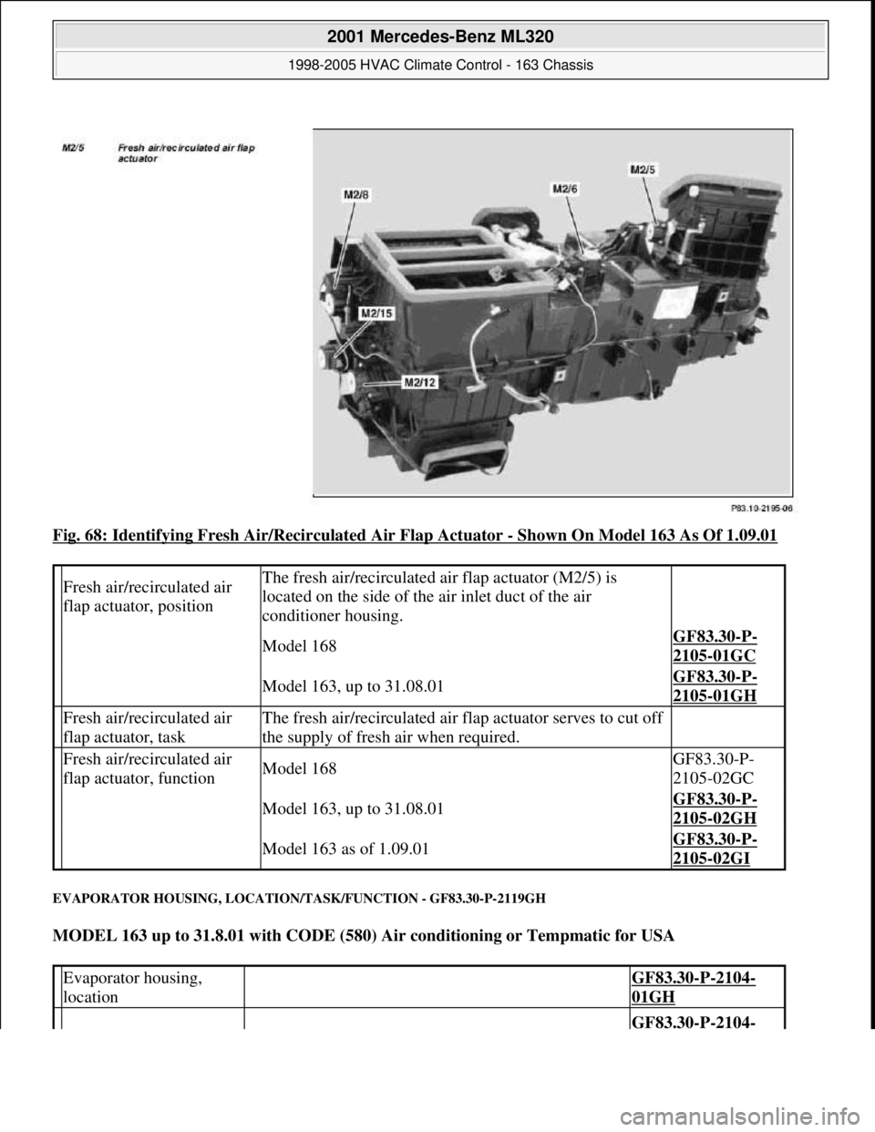
Fig. 68: Identifying Fresh Air/Recirculated Air Flap Actuator - Shown On Model 163 As Of 1.09.01
EVAPORATOR HOUSING, LOCATION/TASK/FUNCTION - GF83.30-P-2119GH
MODEL 163 up to 31.8.01 with CODE (580) Air conditioning or Tempmatic for USA
Fresh air/recirculated air
flap actuator, positionThe fresh air/recirculated air flap actuator (M2/5) is
located on the side of the air inlet duct of the air
conditioner housing.
Model 168GF83.30-P-
2105-01GC
Model 163, up to 31.08.01GF83.30-P-
2105-01GH
Fresh air/recirculated air
flap actuator, taskThe fresh air/recirculated air flap actuator serves to cut off
the supply of fresh air when required.
Fresh air/recirculated air
flap actuator, functionModel 168GF83.30-P-
2105-02GC
Model 163, up to 31.08.01GF83.30-P-
2105-02GH
Model 163 as of 1.09.01GF83.30-P-
2105-02GI
Evaporator housing,
location GF83.30-P-2104-
01GH
GF83.30-P-2104-
2001 Mercedes-Benz ML320
1998-2005 HVAC Climate Control - 163 Chassis
me
Saturday, October 02, 2010 3:23:15 PMPage 77 © 2006 Mitchell Repair Information Company, LLC.
Page 3322 of 4133
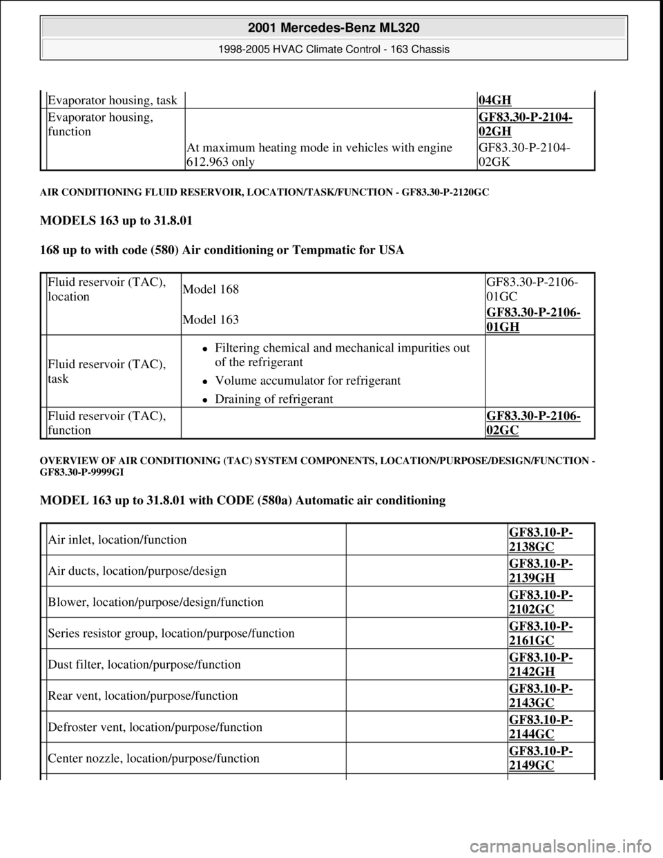
AIR CONDITIONING FLUID RESERVOIR, LOCATION/TASK/FUNCTION - GF83.30-P-2120GC
MODELS 163 up to 31.8.01
168 up to with code (580) Air conditioning or Tempmatic for USA
OVERVIEW OF AIR CONDITIONING (TAC) SYSTEM COMPONENTS, LOCATION/PURPOSE/DESIGN/FUNCTION -
GF83.30-P-9999GI
MODEL 163 up to 31.8.01 with CODE (580a) Automatic air conditioning
Evaporator housing, task 04GH
Evaporator housing,
function GF83.30-P-2104-
02GH
At maximum heating mode in vehicles with engine
612.963 onlyGF83.30-P-2104-
02GK
Fluid reservoir (TAC),
locationModel 168GF83.30-P-2106-
01GC
Model 163GF83.30-P-2106-
01GH
Fluid reservoir (TAC),
task
Filtering chemical and mechanical impurities out
of the refrigerant
Volume accumulator for refrigerant
Draining of refrigerant
Fluid reservoir (TAC),
function GF83.30-P-2106-
02GC
Air inlet, location/function GF83.10-P-
2138GC
Air ducts, location/purpose/design GF83.10-P-
2139GH
Blower, location/purpose/design/function GF83.10-P-
2102GC
Series resistor group, location/purpose/function GF83.10-P-
2161GC
Dust filter, location/purpose/function GF83.10-P-
2142GH
Rear vent, location/purpose/function GF83.10-P-
2143GC
Defroster vent, location/purpose/function GF83.10-P-
2144GC
Center nozzle, location/purpose/function GF83.10-P-
2149GC
2001 Mercedes-Benz ML320
1998-2005 HVAC Climate Control - 163 Chassis
me
Saturday, October 02, 2010 3:23:15 PMPage 78 © 2006 Mitchell Repair Information Company, LLC.
Page 3323 of 4133
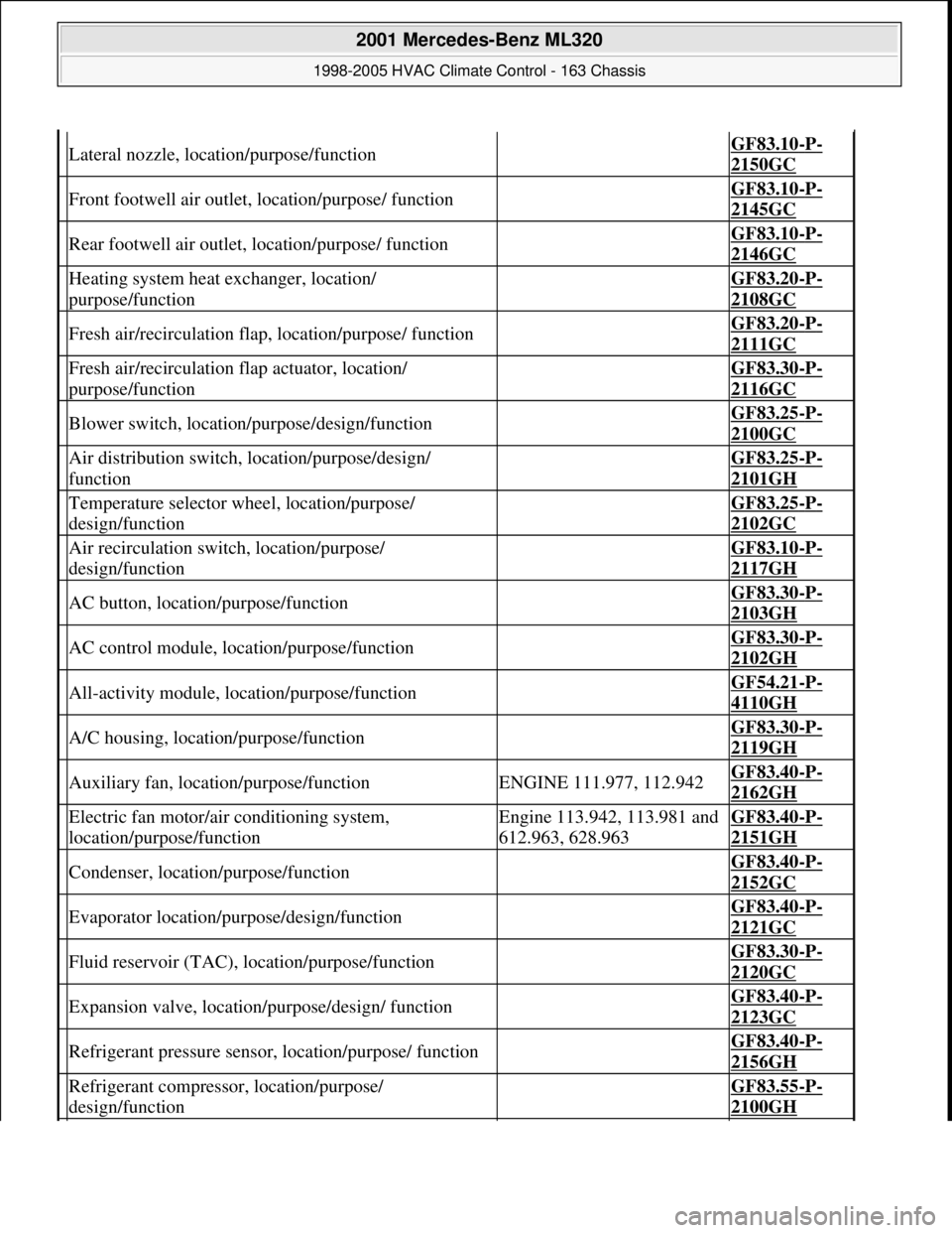
Lateral nozzle, location/purpose/function GF83.10-P-
2150GC
Front footwell air outlet, location/purpose/ function GF83.10-P-
2145GC
Rear footwell air outlet, location/purpose/ function GF83.10-P-
2146GC
Heating system heat exchanger, location/
purpose/function GF83.20-P-
2108GC
Fresh air/recirculation flap, location/purpose/ function GF83.20-P-
2111GC
Fresh air/recirculation flap actuator, location/
purpose/function GF83.30-P-
2116GC
Blower switch, location/purpose/design/function GF83.25-P-
2100GC
Air distribution switch, location/purpose/design/
function GF83.25-P-
2101GH
Temperature selector wheel, location/purpose/
design/function GF83.25-P-
2102GC
Air recirculation switch, location/purpose/
design/function GF83.10-P-
2117GH
AC button, location/purpose/function GF83.30-P-
2103GH
AC control module, location/purpose/function GF83.30-P-
2102GH
All-activity module, location/purpose/function GF54.21-P-
4110GH
A/C housing, location/purpose/function GF83.30-P-
2119GH
Auxiliary fan, location/purpose/functionENGINE 111.977, 112.942GF83.40-P-
2162GH
Electric fan motor/air conditioning system,
location/purpose/functionEngine 113.942, 113.981 and
612.963, 628.963GF83.40-P-
2151GH
Condenser, location/purpose/function GF83.40-P-
2152GC
Evaporator location/purpose/design/function GF83.40-P-
2121GC
Fluid reservoir (TAC), location/purpose/function GF83.30-P-
2120GC
Expansion valve, location/purpose/design/ function GF83.40-P-
2123GC
Refrigerant pressure sensor, location/purpose/ function GF83.40-P-
2156GH
Refrigerant compressor, location/purpose/
design/function GF83.55-P-
2100GH
2001 Mercedes-Benz ML320
1998-2005 HVAC Climate Control - 163 Chassis
me
Saturday, October 02, 2010 3:23:15 PMPage 79 © 2006 Mitchell Repair Information Company, LLC.
Page 3324 of 4133
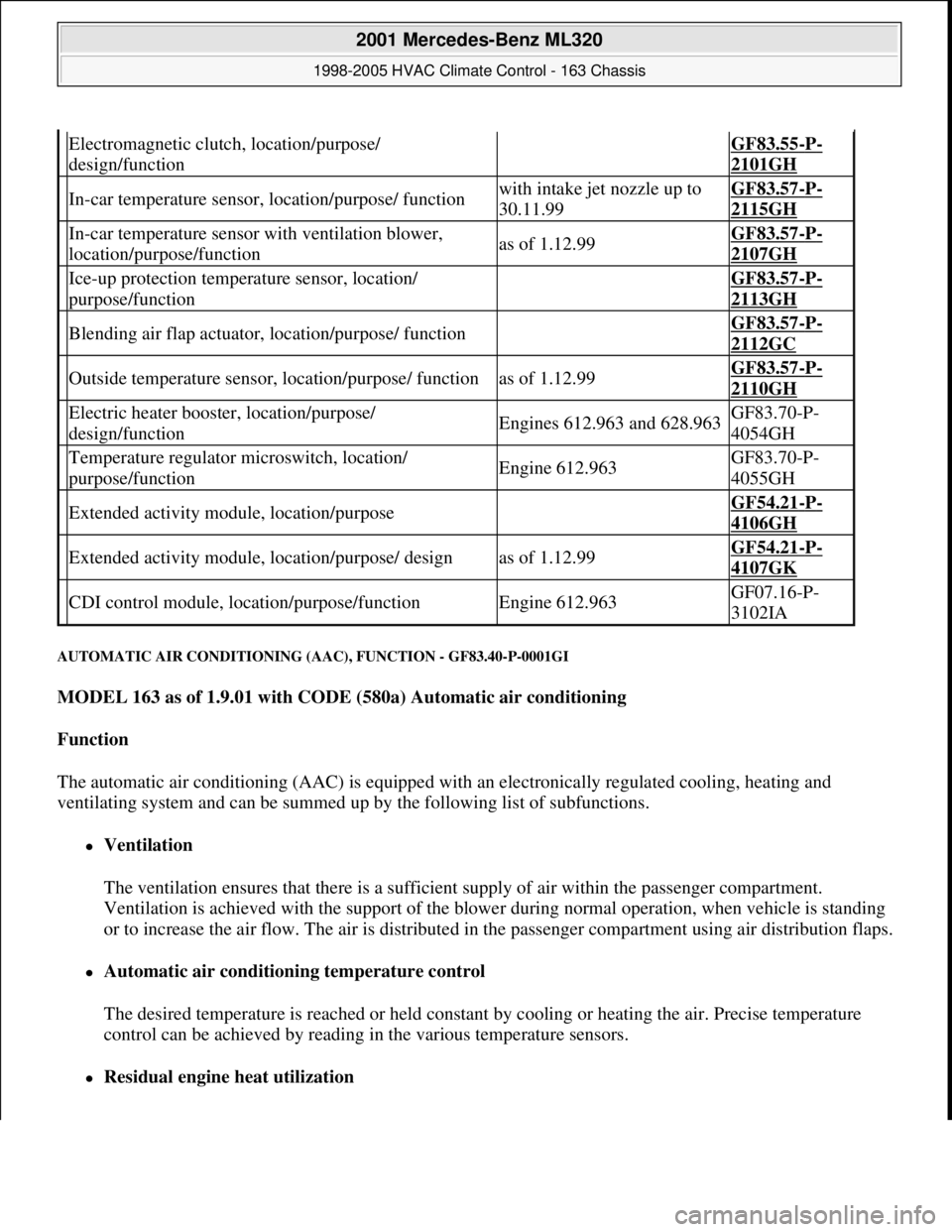
AUTOMATIC AIR CONDITIONING (AAC), FUNCTION - GF83.40-P-0001GI
MODEL 163 as of 1.9.01 with CODE (580a) Automatic air conditioning
Function
The automatic air conditioning (AAC) is equipped with an electronically regulated cooling, heating and
ventilating system and can be summed up by the following list of subfunctions.
Ventilation
The ventilation ensures that there is a sufficient supply of air within the passenger compartment.
Ventilation is achieved with the support of the blower during normal operation, when vehicle is standing
or to increase the air flow. The air is distributed in the passenger compartment using air distribution flaps.
Automatic air conditioning temperature control
The desired temperature is reached or held constant by cooling or heating the air. Precise temperature
control can be achieved by reading in the various temperature sensors.
Residual engine heat utilization
Electromagnetic clutch, location/purpose/
design/function GF83.55-P-
2101GH
In-car temperature sensor, location/purpose/ functionwith intake jet nozzle up to
30.11.99GF83.57-P-
2115GH
In-car temperature sensor with ventilation blower,
location/purpose/functionas of 1.12.99GF83.57-P-
2107GH
Ice-up protection temperature sensor, location/
purpose/function GF83.57-P-
2113GH
Blending air flap actuator, location/purpose/ function GF83.57-P-
2112GC
Outside temperature sensor, location/purpose/ functionas of 1.12.99GF83.57-P-
2110GH
Electric heater booster, location/purpose/
design/functionEngines 612.963 and 628.963GF83.70-P-
4054GH
Temperature regulator microswitch, location/
purpose/functionEngine 612.963GF83.70-P-
4055GH
Extended activity module, location/purpose GF54.21-P-
4106GH
Extended activity module, location/purpose/ designas of 1.12.99GF54.21-P-
4107GK
CDI control module, location/purpose/functionEngine 612.963GF07.16-P-
3102IA
2001 Mercedes-Benz ML320
1998-2005 HVAC Climate Control - 163 Chassis
me
Saturday, October 02, 2010 3:23:16 PMPage 80 © 2006 Mitchell Repair Information Company, LLC.
Page 3325 of 4133
The residual engine heat utilization system allows the vehicle to be heated even when the ignition is
switched OFF. To do so the system utilizes the residual heat from the engine and guides it via the
blower into the passenger compartment. The heating water circulation pump ensures that the
coolant is properly circulated.
Automatic air conditioning push-button control module
The automatic air conditioning can be operated by the driver using various tip switches. Apart from this
the push-
button control module reads in different sensor signals, processes them and controls components
in the automatic air conditioning.
Rear ventilation control panel
The operator can intervene in the automatic regulation of the rear ventilation through the automatic air
conditioning by using the rear ventilation control panel and adjust it accordingly to suit needs at any
given time. With the aid of the air distribution switch and blower switch the operator can accommodate
his/her own wishes. The correspondingly altered function is then no longer regulated by the automatic air
conditioning.
By pressing the automatic control button the manually initiated settings can be reset and thus regulated
again by the automatic air conditioning.
Regulation of the air quantity and air distribution ensues thus solely by way of the automatic air
conditioning push-button control module.
Heater circuit
Coolant is heated by the engine. Subsequently, the heated coolant is then routed through the heat exchanger,
where the heat is dissipated to the air in the passenger compartment. The heater return line, in which the heating
water circulation pump is located, takes the coolant back to the coolant pump.
The heating water circulation pump ensures that the coolant is properly circulated.
The coolant flows through the heat exchanger permanently.
Depending upon the desired in-car temperature, regulation is conducted over the blending air flaps, which are
operated by the blending air flap actuator motor.
Heater operation with heater booster in vehicles with OM 612.963
In vehicles equipped with direct-injection diesel engines, an electrical heater booster is additionally installed in
the evaporator housing downstream of the heat exchanger, in order to compensate the heater output deficit
which occurs in the case of certain operating conditions.
The 3 heating elements in the heater booster are supplied with current, as a result of which they are heated and
start to glow. As a result of the structural conditions, it is ensured that the drawn in fresh air flows directly past
the electric heater booster, and is therefore heated.
2001 Mercedes-Benz ML320
1998-2005 HVAC Climate Control - 163 Chassis
me
Saturday, October 02, 2010 3:23:16 PMPage 81 © 2006 Mitchell Repair Information Company, LLC.
Page 3326 of 4133
Refrigerant circuit
The refrigerant compressor serves to compresses the gaseous refrigerant which heats up during the process, is
then routed into the condenser and thus cooled down. After purification in the fluid reservoir the liquid
refrigerant is injected into the evaporator. The refrigerant is vaporized and cools down. The refrigerant
compressor intakes the refrigerant again which has turned gaseous through the heat absorption process.
TABLE OF CONTENTS, AUTOMATIC AIR CONDITIONING (AAC) FUNCTION DESCRIPTION - GF83.40-P-0999GI
MODEL 163 as of 1.9.01 with CODE (580a) Automatic air conditioning
Ventilation, function GF83.10-P-2000GI
Heater circuit function GF83.20-P-2003GH
Automatic air conditioning push-button control module, function GF83.40-P-2000GI
Rear ventilation control panel, function GF83.40-P-2007GI
Refrigerant circuit function GF83.40-P-2001GI
Temperature control, function GF83.57-P-2000GI
Heater booster (ZUH), function GF83.70-P-0005GH
Residual engine heat utilization system, function GF83.75-P-2000GI
Automatic air conditioning (AAC), function GF83.40-P-
0001GI
Ventilation system function GF83.10-P-
2000GI
Heater circuit function GF83.20-P-
2003GH
Automatic air conditioning push-button control module, function GF83.40-P-
2000GI
Rear ventilation control panel, function GF83.40-P-
2007GI
Refrigerant circuit function GF83.40-P-
2001GI
Temperature control, function GF83.57-P-
2000GI
Heater booster (ZUH), function Engine
612.963GF83.70-P-
0005GH
Start heater operation, function Engine
612.963GF83.70-P-
2000GH
End heater operation, function Engine
612.963GF83.70-P-
2002GH
Regulate heater operation, function Engine
612.963GF83.70-P-
2004GH
Cancel heater operation, function Engine GF83.70-P-
2001 Mercedes-Benz ML320
1998-2005 HVAC Climate Control - 163 Chassis
me
Saturday, October 02, 2010 3:23:16 PMPage 82 © 2006 Mitchell Repair Information Company, LLC.