MERCEDES-BENZ ML430 1997 Complete Repair Manual
Manufacturer: MERCEDES-BENZ, Model Year: 1997, Model line: ML430, Model: MERCEDES-BENZ ML430 1997Pages: 4133, PDF Size: 88.89 MB
Page 3951 of 4133

AR01.20-P-5014-02C
Remove/install cylinder head cover trim
Crankcase ventilation, cylinder head cover
Number
Designation
Engine
613.960/
961
BA01.20-P-1002-01A
Screw of trim panel of cylinder head cover
to cylinder head cover
Nm
10
BA01.20-P-1003-01A
Screw attaching cover panel to charge air
distribution pipe
Nm
10
Crankcase ventilation, cylinder head cover
Number
Designation
Engine
648
BA01.20-P-1002-01G
Bolt, trim panel of cylinder
head cover to cylinder head
Nm
9
BA01.20-P-1003-01G
Bolt, cover charge air
distribution pipe
Nm
9
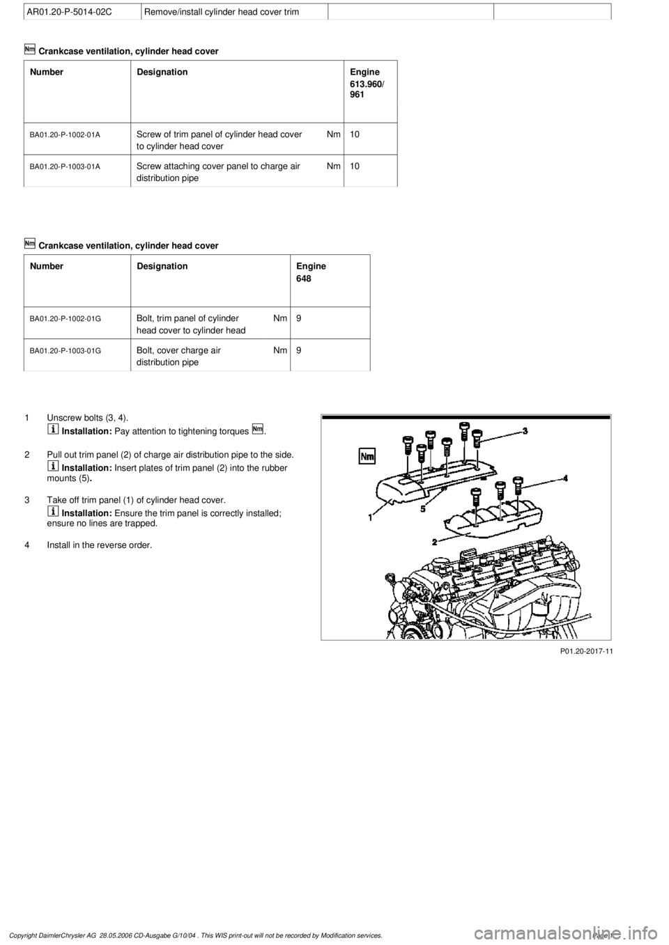
P01.20-2017-11
1
Unscrew bolts (3, 4).
Installation:
Pay attention to tightening torques
.
2
Pull out trim panel (2) of charge air distribution pipe to the side.
Installation:
Insert plates of trim panel (2) into the rubber
mounts (5)
.
3
Take off trim panel (1) of cylinder head cover.
Installation:
Ensure the trim panel is correctly installed;
ensure no lines are trapped.
4
Install in the reverse order.
Copyright DaimlerChrysler AG 28.05.2006 CD-Ausgabe G/10/04 . This WIS print-out will not be recorde
d by Modification services.
Page 1
Page 3952 of 4133

GF54.50-P-4101GH
Electronic compass, location/purpose/design
24.3.00
MODEL
163 as of 1.9.00 with CODE (245) Trip computer
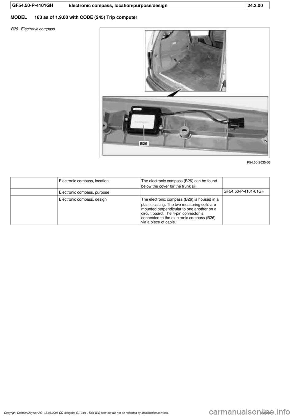
P54.50-2035-06
B26
Electronic compass
Electronic compass, location
The electronic compass (B26) can be found
below the cover for the trunk sill.
Electronic compass, purpose
GF54.50-P-4101-01GH
Electronic compass, design
The electronic compass (B26) is housed in a
plastic casing. The two measuring coils are
mounted perpendicular to one another on a
circuit board. The 4-pin connector is
connected to the electronic compass (B26)
via a piece of cable.
Copyright DaimlerChrysler AG 18.05.2006 CD-Ausgabe G/10/04 . This WIS print-out will not be recorde
d by Modification services.
Page 1
Page 3953 of 4133

GF54.50-P-4101-01GH
Electronic compass, purpose
n
The electronic compass (B26) determines the current route
of the
vehicle using the
earth's magnetic field
and passes the appropriate
data to the trip computer control module (N41) via a two-wire
interface (RS485).
The compass has a calibration mode to allow the route to be
determined as accurately as possible. In this mode the compass can
be adapted to the magnetic conditions around the vehicle.
Copyright DaimlerChrysler AG 18.05.2006 CD-Ausgabe G/10/04 . This WIS print-out will not be recorde
d by Modification services.
Page 1
Page 3954 of 4133

GF54.50-P-4100-02GH
Trip computer control module, design
n
The trip computer control module (TRIP, N41) consists of the
following components:
D
Electronics unit
D
LCD display
D
Reset button (left button, N41s1)
D
Mode button (right button, N41s2)
D
Inclination sensor (N41b1)
D
Glass breakage sensor (N41b2)
D
CAN interface
D
Alarm bus to all activity module (AAM, N10)
D
as of 1.9.00: Interface (RS 485) to electronic compass (B26)
Copyright DaimlerChrysler AG 18.05.2006 CD-Ausgabe G/10/04 . This WIS print-out will not be recorde
d by Modification services.
Page 1
Page 3955 of 4133

GF54.50-P-4100-02GH
Trip computer control module, design
n
The trip computer control module (TRIP, N41) consists of the
following components:
D
Electronics unit
D
LCD display
D
Reset button (left button, N41s1)
D
Mode button (right button, N41s2)
D
Inclination sensor (N41b1)
D
Glass breakage sensor (N41b2)
D
CAN interface
D
Alarm bus to all activity module (AAM, N10)
D
as of 1.9.00: Interface (RS 485) to electronic compass (B26)
Copyright DaimlerChrysler AG 18.05.2006 CD-Ausgabe G/10/04 . This WIS print-out will not be recorde
d by Modification services.
Page 1
Page 3956 of 4133

GF54.30-P-2016A
Trip computer interface, location/task
7.7.99
MODEL
129, 140 as of 1.6.96
The trip computer receives the following information via the trip
computer interface (2 lines):
D
Driving speed
D
Mileage
D
Time
-----------------------------------------------------------------------------------------
The trip computer receives information about fuel consumption
directly from the fuel level sensor.
-----------------------------------------------------------------------------------------
Copyright DaimlerChrysler AG 05.06.2006 CD-Ausgabe G/10/04 . This WIS print-out will not be recorde
d by Modification services.
Page 1
Page 3957 of 4133

GF54.50-P-4100GH
Trip computer control module, location/task/design
24.3.00
MODEL
163 as of 1.9.00 with CODE (245) Trip computer
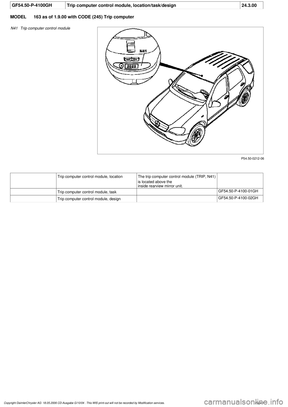
P54.50-0212-06
N41
Trip computer control module
Trip computer control module, location
The trip computer control module (TRIP, N41)
is located above the
inside rearview mirror unit.
Trip computer control module, task
GF54.50-P-4100-01GH
Trip computer control module, design
GF54.50-P-4100-02GH
Copyright DaimlerChrysler AG 18.05.2006 CD-Ausgabe G/10/04 . This WIS print-out will not be recorde
d by Modification services.
Page 1
Page 3958 of 4133

AR54.50-P-0001GH
Remove, install trip computer
17.12.98
MODEL
163.113 /128 /136 /154 /157 /172 /174 /175 with CODE (245) Trip computer
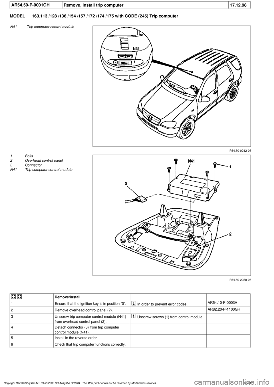
P54.50-0212-06
N41
Trip computer control module
P54.50-2030-06
1
Bolts
2
Overhead control panel
3
Connector
N41
Trip computer control module
Remove/install
1
Ensure that the ignition key is in position "0".
In order to prevent error codes.
AR54.10-P-0003A
2
Remove overhead control panel (2).
AR82.20-P-1100GH
3
Unscrew trip computer control module (N41)
from overhead control panel (2).
Unscrew screws (1) from control module.
4
Detach connector (3) from trip computer
control module (N41).
5
Install in the reverse order
6
Check that trip computer functions correctly.
Copyright DaimlerChrysler AG 09.05.2006 CD-Ausgabe G/10/04 . This WIS print-out will not be recorde
d by Modification services.
Page 1
Page 3959 of 4133

GF54.50-P-4100-01GH
Trip computer control module, task
n
The trip compute control module (TRIP, N41) has the following tasks:
D
Display and calculate the current and average fuel consumption
D
Display and calculate the likely range
D
Display the trip time
D
Display the date
D
as of 1.9.00: Display the route (compass)
On vehicles with
ATA
also to:
D
Display the status of the ATA sensory system (on/OFF)
D
Output a "life sign" on the alarm bus to the all activity module
(AAM, N10)
D
Output an alarm signal on the alarm bus to the all activity
module (AAM, N10) when the
glass breakage sensor (N41b2)
is triggered
D
Output an alarm signal on the alarm bus to the all activity
module (AAM, N10) when the
inclination sensor (N41b2) is
triggered
Copyright DaimlerChrysler AG 18.05.2006 CD-Ausgabe G/10/04 . This WIS print-out will not be recorde
d by Modification services.
Page 1
Page 3960 of 4133

AD54.30-P-5000-03A
Directly controlled display instruments
troubleshooting chart IC
Directly controlled display instruments or indicator
lamp/warning message:
D
Outside temperature indicator
D
Fuel gauge
D
Oil pressure gauge (models 129 and 140 only)
D
Left turn signal indicator lamp
D
Right turn signal indicator lamp
D
High beam indicator lamp
D
Fuel reserve indicator lamp
D
Airbag SRS indicator lamp/MIL
D
AIRBAG OFF indicator lamp (only model 163 except
I )
D
Low brake fluid level/parking brake indicator lamp (only brake
fluid direct)
(both functions via CAN on model 163)
D
Low windshield washer fluid level indicator lamp (except
models 163 and 168)
D
Low ECL indicator lamp (except models 163 and 168)
D
Generator charge indicator lamp
D
Seat belt reminder lamp
D
Seat belt/backrest lock reminder lamp
D
Exterior lamp failure indicator lamp
D
Hydraulic fluid level indicator lamp (models 202 and 210 only)
D
ADS MIL, suspension
D
Turn signal clicking
D
Seat belt reminder lamp
D
Light reminder lamp
D
Key reminder lamp
D
Soft top reminder lamp (model 170 only)
D
Steering lock warning lamp (
I )
Copyright DaimlerChrysler AG 05.06.2006 CD-Ausgabe G/10/04 . This WIS print-out will not be recorde
d by Modification services.
Page 1