MERCEDES-BENZ SPRINTER 2005 Service Repair Manual
Manufacturer: MERCEDES-BENZ, Model Year: 2005, Model line: SPRINTER, Model: MERCEDES-BENZ SPRINTER 2005Pages: 1232, PDF Size: 39.23 MB
Page 291 of 1232
washer hose fittings cannot be repaired. If these fittings
are faulty or damaged, they must be replaced.
OPERATION
Washer fluid in the washer reservoir is pressurized
and fed by the washer pump/motor through the
washer system plumbing and fittings to the two
washer nozzles. Whenever routing the washer hose
or a wire harness containing a washer hose, it must
be routed away from hot, sharp, or moving parts;
and, sharp bends that might pinch the hose must be
avoided.
WASHER NOZZLE
DESCRIPTION
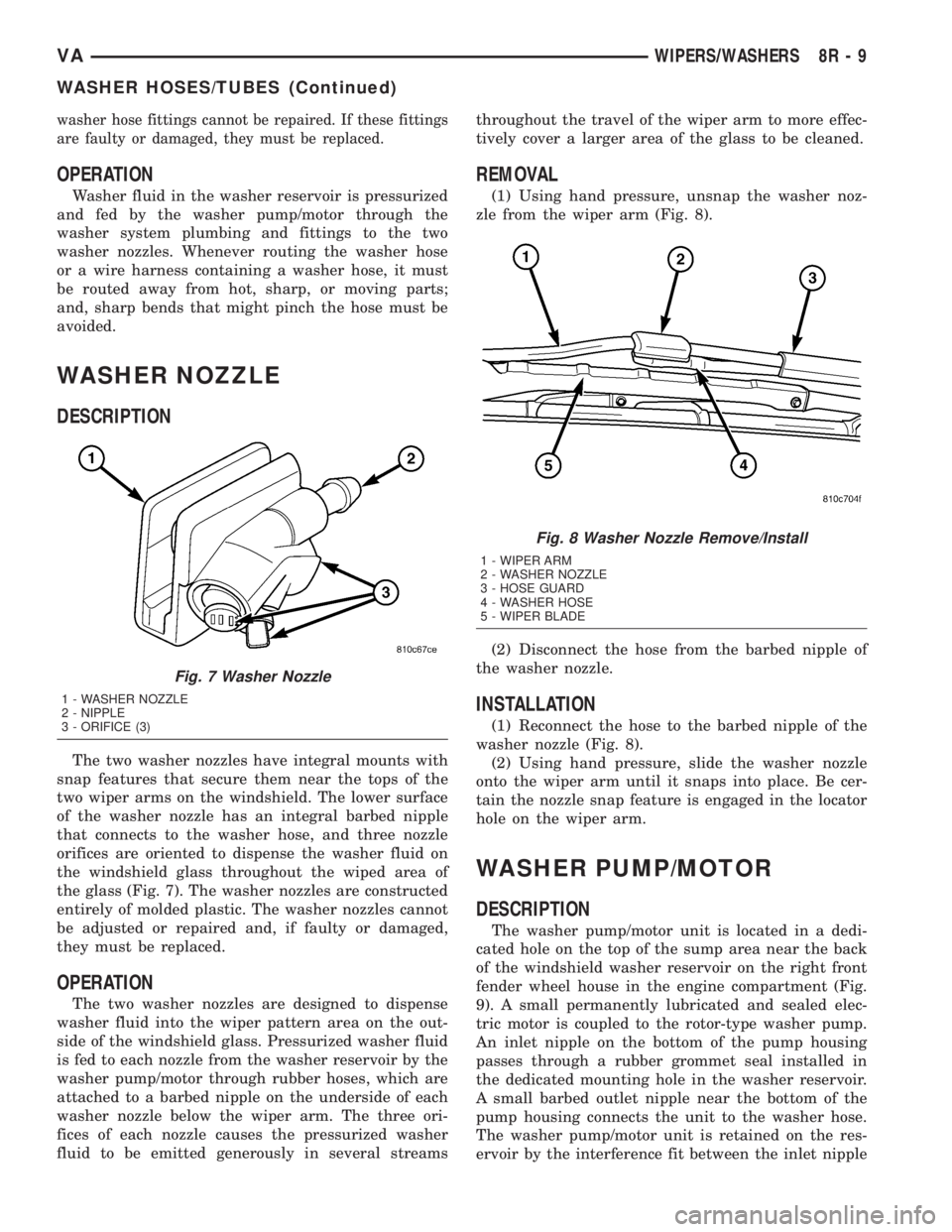
The two washer nozzles have integral mounts with
snap features that secure them near the tops of the
two wiper arms on the windshield. The lower surface
of the washer nozzle has an integral barbed nipple
that connects to the washer hose, and three nozzle
orifices are oriented to dispense the washer fluid on
the windshield glass throughout the wiped area of
the glass (Fig. 7). The washer nozzles are constructed
entirely of molded plastic. The washer nozzles cannot
be adjusted or repaired and, if faulty or damaged,
they must be replaced.
OPERATION
The two washer nozzles are designed to dispense
washer fluid into the wiper pattern area on the out-
side of the windshield glass. Pressurized washer fluid
is fed to each nozzle from the washer reservoir by the
washer pump/motor through rubber hoses, which are
attached to a barbed nipple on the underside of each
washer nozzle below the wiper arm. The three ori-
fices of each nozzle causes the pressurized washer
fluid to be emitted generously in several streamsthroughout the travel of the wiper arm to more effec-
tively cover a larger area of the glass to be cleaned.
REMOVAL
(1) Using hand pressure, unsnap the washer noz-
zle from the wiper arm (Fig. 8).
(2) Disconnect the hose from the barbed nipple of
the washer nozzle.
INSTALLATION
(1) Reconnect the hose to the barbed nipple of the
washer nozzle (Fig. 8).
(2) Using hand pressure, slide the washer nozzle
onto the wiper arm until it snaps into place. Be cer-
tain the nozzle snap feature is engaged in the locator
hole on the wiper arm.
WASHER PUMP/MOTOR
DESCRIPTION
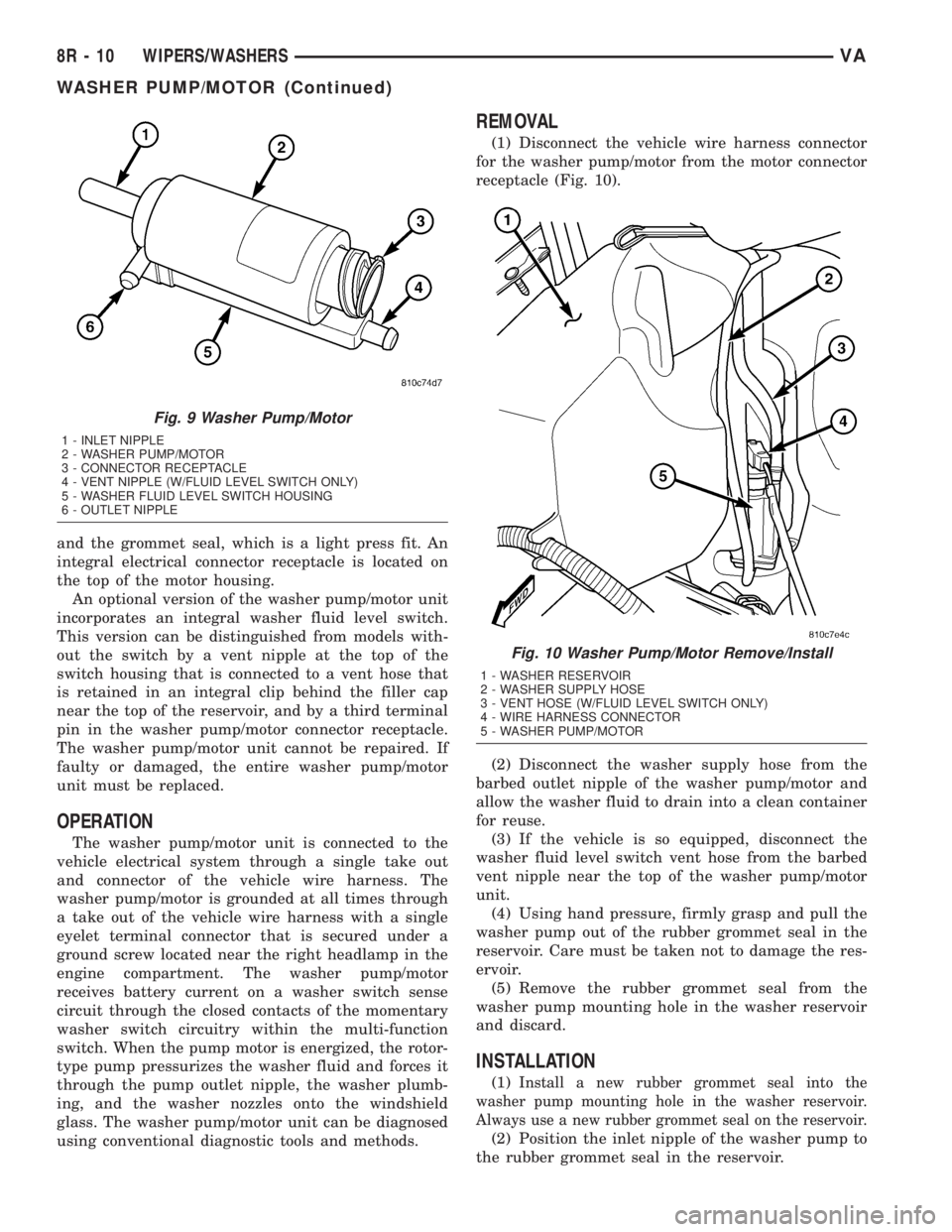
The washer pump/motor unit is located in a dedi-
cated hole on the top of the sump area near the back
of the windshield washer reservoir on the right front
fender wheel house in the engine compartment (Fig.
9). A small permanently lubricated and sealed elec-
tric motor is coupled to the rotor-type washer pump.
An inlet nipple on the bottom of the pump housing
passes through a rubber grommet seal installed in
the dedicated mounting hole in the washer reservoir.
A small barbed outlet nipple near the bottom of the
pump housing connects the unit to the washer hose.
The washer pump/motor unit is retained on the res-
ervoir by the interference fit between the inlet nipple
Fig. 7 Washer Nozzle
1 - WASHER NOZZLE
2 - NIPPLE
3 - ORIFICE (3)
Fig. 8 Washer Nozzle Remove/Install
1 - WIPER ARM
2 - WASHER NOZZLE
3 - HOSE GUARD
4 - WASHER HOSE
5 - WIPER BLADE
VAWIPERS/WASHERS 8R - 9
WASHER HOSES/TUBES (Continued)
Page 292 of 1232
and the grommet seal, which is a light press fit. An
integral electrical connector receptacle is located on
the top of the motor housing.
An optional version of the washer pump/motor unit
incorporates an integral washer fluid level switch.
This version can be distinguished from models with-
out the switch by a vent nipple at the top of the
switch housing that is connected to a vent hose that
is retained in an integral clip behind the filler cap
near the top of the reservoir, and by a third terminal
pin in the washer pump/motor connector receptacle.
The washer pump/motor unit cannot be repaired. If
faulty or damaged, the entire washer pump/motor
unit must be replaced.
OPERATION
The washer pump/motor unit is connected to the
vehicle electrical system through a single take out
and connector of the vehicle wire harness. The
washer pump/motor is grounded at all times through
a take out of the vehicle wire harness with a single
eyelet terminal connector that is secured under a
ground screw located near the right headlamp in the
engine compartment. The washer pump/motor
receives battery current on a washer switch sense
circuit through the closed contacts of the momentary
washer switch circuitry within the multi-function
switch. When the pump motor is energized, the rotor-
type pump pressurizes the washer fluid and forces it
through the pump outlet nipple, the washer plumb-
ing, and the washer nozzles onto the windshield
glass. The washer pump/motor unit can be diagnosed
using conventional diagnostic tools and methods.
REMOVAL
(1) Disconnect the vehicle wire harness connector
for the washer pump/motor from the motor connector
receptacle (Fig. 10).
(2) Disconnect the washer supply hose from the
barbed outlet nipple of the washer pump/motor and
allow the washer fluid to drain into a clean container
for reuse.
(3) If the vehicle is so equipped, disconnect the
washer fluid level switch vent hose from the barbed
vent nipple near the top of the washer pump/motor
unit.
(4) Using hand pressure, firmly grasp and pull the
washer pump out of the rubber grommet seal in the
reservoir. Care must be taken not to damage the res-
ervoir.
(5) Remove the rubber grommet seal from the
washer pump mounting hole in the washer reservoir
and discard.
INSTALLATION
(1)Install a new rubber grommet seal into the
washer pump mounting hole in the washer reservoir.
Always use a new rubber grommet seal on the reservoir.
(2) Position the inlet nipple of the washer pump to
the rubber grommet seal in the reservoir.
Fig. 9 Washer Pump/Motor
1 - INLET NIPPLE
2 - WASHER PUMP/MOTOR
3 - CONNECTOR RECEPTACLE
4 - VENT NIPPLE (W/FLUID LEVEL SWITCH ONLY)
5 - WASHER FLUID LEVEL SWITCH HOUSING
6 - OUTLET NIPPLE
Fig. 10 Washer Pump/Motor Remove/Install
1 - WASHER RESERVOIR
2 - WASHER SUPPLY HOSE
3 - VENT HOSE (W/FLUID LEVEL SWITCH ONLY)
4 - WIRE HARNESS CONNECTOR
5 - WASHER PUMP/MOTOR
8R - 10 WIPERS/WASHERSVA
WASHER PUMP/MOTOR (Continued)
Page 293 of 1232
(3) Using hand pressure, press firmly and evenly
on the washer pump until the inlet nipple is fully
seated in the rubber grommet seal in the washer res-
ervoir mounting hole (Fig. 10).
(4)
If the vehicle is so equipped, reconnect the
washer fluid level switch vent hose to the barbed vent
nipple at the top of the washer pump/motor housing.
(5) Reconnect the washer hose to the barbed outlet
nipple of the washer pump.
(6) Reconnect the vehicle wire harness connector
for the washer pump/motor unit to the motor connec-
tor receptacle.
(7) Refill the washer reservoir with the washer
fluid drained from the reservoir during the removal
procedure.
WASHER RESERVOIR
DESCRIPTION
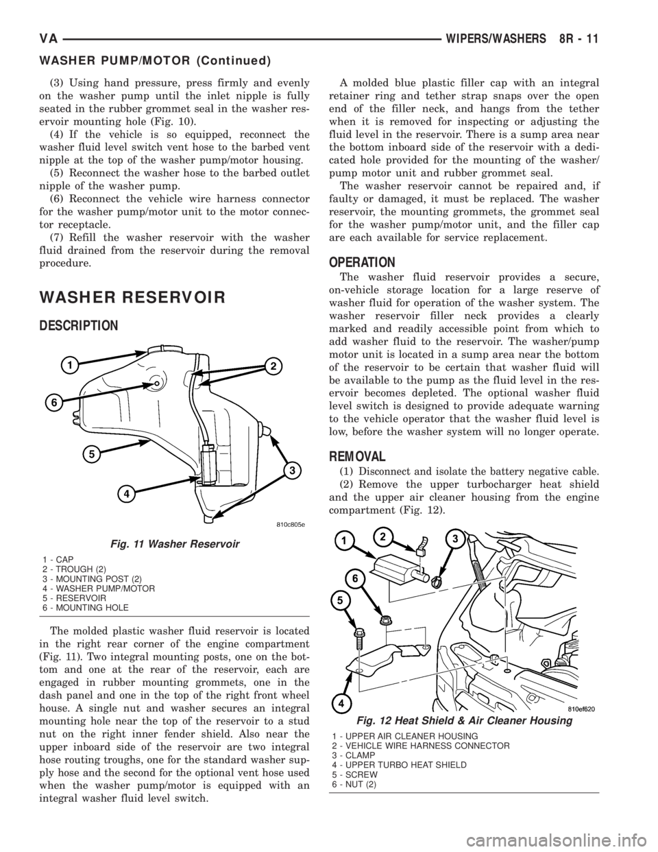
The molded plastic washer fluid reservoir is located
in the right rear corner of the engine compartment
(Fig. 11). Two integral mounting posts, one on the bot-
tom and one at the rear of the reservoir, each are
engaged in rubber mounting grommets, one in the
dash panel and one in the top of the right front wheel
house. A single nut and washer secures an integral
mounting hole near the top of the reservoir to a stud
nut on the right inner fender shield. Also near the
upper inboard side of the reservoir are two integral
hose routing troughs, one for the standard washer sup-
ply hose and the second for the optional vent hose used
when the washer pump/motor is equipped with an
integral washer fluid level switch.
A molded blue plastic filler cap with an integral
retainer ring and tether strap snaps over the open
end of the filler neck, and hangs from the tether
when it is removed for inspecting or adjusting the
fluid level in the reservoir. There is a sump area near
the bottom inboard side of the reservoir with a dedi-
cated hole provided for the mounting of the washer/
pump motor unit and rubber grommet seal.
The washer reservoir cannot be repaired and, if
faulty or damaged, it must be replaced. The washer
reservoir, the mounting grommets, the grommet seal
for the washer pump/motor unit, and the filler cap
are each available for service replacement.
OPERATION
The washer fluid reservoir provides a secure,
on-vehicle storage location for a large reserve of
washer fluid for operation of the washer system. The
washer reservoir filler neck provides a clearly
marked and readily accessible point from which to
add washer fluid to the reservoir. The washer/pump
motor unit is located in a sump area near the bottom
of the reservoir to be certain that washer fluid will
be available to the pump as the fluid level in the res-
ervoir becomes depleted. The optional washer fluid
level switch is designed to provide adequate warning
to the vehicle operator that the washer fluid level is
low, before the washer system will no longer operate.
REMOVAL
(1)Disconnect and isolate the battery negative cable.
(2) Remove the upper turbocharger heat shield
and the upper air cleaner housing from the engine
compartment (Fig. 12).
Fig. 11 Washer Reservoir
1 - CAP
2 - TROUGH (2)
3 - MOUNTING POST (2)
4 - WASHER PUMP/MOTOR
5 - RESERVOIR
6 - MOUNTING HOLE
Fig. 12 Heat Shield & Air Cleaner Housing
1 - UPPER AIR CLEANER HOUSING
2 - VEHICLE WIRE HARNESS CONNECTOR
3 - CLAMP
4 - UPPER TURBO HEAT SHIELD
5 - SCREW
6 - NUT (2)
VAWIPERS/WASHERS 8R - 11
WASHER PUMP/MOTOR (Continued)
Page 294 of 1232
(3) Disconnect the vehicle wire harness connector
for the washer pump/motor unit from the motor con-
nector receptacle.
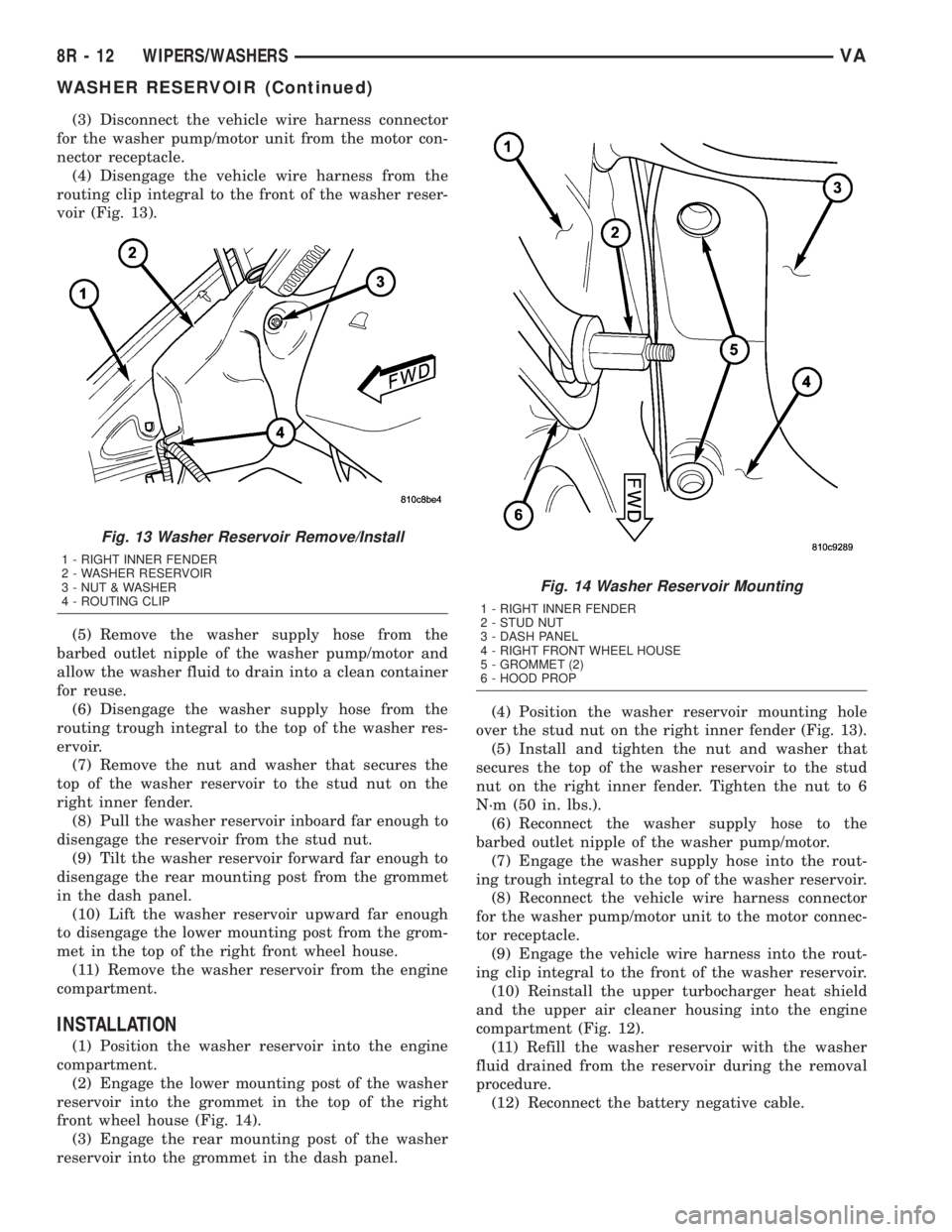
(4) Disengage the vehicle wire harness from the
routing clip integral to the front of the washer reser-
voir (Fig. 13).
(5) Remove the washer supply hose from the
barbed outlet nipple of the washer pump/motor and
allow the washer fluid to drain into a clean container
for reuse.
(6) Disengage the washer supply hose from the
routing trough integral to the top of the washer res-
ervoir.
(7) Remove the nut and washer that secures the
top of the washer reservoir to the stud nut on the
right inner fender.
(8) Pull the washer reservoir inboard far enough to
disengage the reservoir from the stud nut.
(9) Tilt the washer reservoir forward far enough to
disengage the rear mounting post from the grommet
in the dash panel.
(10) Lift the washer reservoir upward far enough
to disengage the lower mounting post from the grom-
met in the top of the right front wheel house.
(11) Remove the washer reservoir from the engine
compartment.
INSTALLATION
(1) Position the washer reservoir into the engine
compartment.
(2) Engage the lower mounting post of the washer
reservoir into the grommet in the top of the right
front wheel house (Fig. 14).
(3) Engage the rear mounting post of the washer
reservoir into the grommet in the dash panel.(4) Position the washer reservoir mounting hole
over the stud nut on the right inner fender (Fig. 13).
(5) Install and tighten the nut and washer that
secures the top of the washer reservoir to the stud
nut on the right inner fender. Tighten the nut to 6
N´m (50 in. lbs.).
(6) Reconnect the washer supply hose to the
barbed outlet nipple of the washer pump/motor.
(7) Engage the washer supply hose into the rout-
ing trough integral to the top of the washer reservoir.
(8) Reconnect the vehicle wire harness connector
for the washer pump/motor unit to the motor connec-
tor receptacle.
(9) Engage the vehicle wire harness into the rout-
ing clip integral to the front of the washer reservoir.
(10) Reinstall the upper turbocharger heat shield
and the upper air cleaner housing into the engine
compartment (Fig. 12).
(11) Refill the washer reservoir with the washer
fluid drained from the reservoir during the removal
procedure.
(12) Reconnect the battery negative cable.
Fig. 13 Washer Reservoir Remove/Install
1 - RIGHT INNER FENDER
2 - WASHER RESERVOIR
3 - NUT & WASHER
4 - ROUTING CLIP
Fig. 14 Washer Reservoir Mounting
1 - RIGHT INNER FENDER
2 - STUD NUT
3 - DASH PANEL
4 - RIGHT FRONT WHEEL HOUSE
5 - GROMMET (2)
6 - HOOD PROP
8R - 12 WIPERS/WASHERSVA
WASHER RESERVOIR (Continued)
Page 295 of 1232
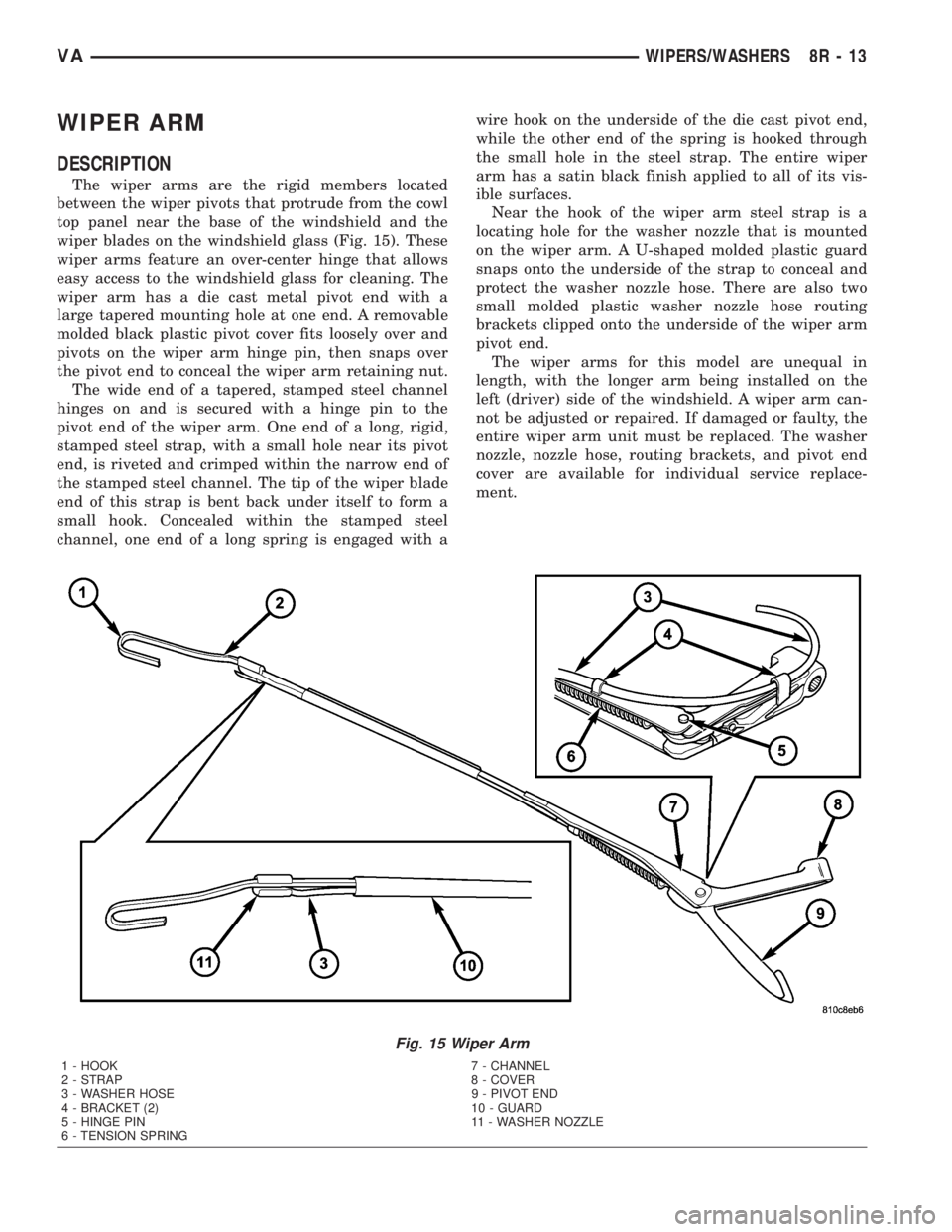
WIPER ARM
DESCRIPTION
The wiper arms are the rigid members located
between the wiper pivots that protrude from the cowl
top panel near the base of the windshield and the
wiper blades on the windshield glass (Fig. 15). These
wiper arms feature an over-center hinge that allows
easy access to the windshield glass for cleaning. The
wiper arm has a die cast metal pivot end with a
large tapered mounting hole at one end. A removable
molded black plastic pivot cover fits loosely over and
pivots on the wiper arm hinge pin, then snaps over
the pivot end to conceal the wiper arm retaining nut.
The wide end of a tapered, stamped steel channel
hinges on and is secured with a hinge pin to the
pivot end of the wiper arm. One end of a long, rigid,
stamped steel strap, with a small hole near its pivot
end, is riveted and crimped within the narrow end of
the stamped steel channel. The tip of the wiper blade
end of this strap is bent back under itself to form a
small hook. Concealed within the stamped steel
channel, one end of a long spring is engaged with awire hook on the underside of the die cast pivot end,
while the other end of the spring is hooked through
the small hole in the steel strap. The entire wiper
arm has a satin black finish applied to all of its vis-
ible surfaces.
Near the hook of the wiper arm steel strap is a
locating hole for the washer nozzle that is mounted
on the wiper arm. A U-shaped molded plastic guard
snaps onto the underside of the strap to conceal and
protect the washer nozzle hose. There are also two
small molded plastic washer nozzle hose routing
brackets clipped onto the underside of the wiper arm
pivot end.
The wiper arms for this model are unequal in
length, with the longer arm being installed on the
left (driver) side of the windshield. A wiper arm can-
not be adjusted or repaired. If damaged or faulty, the
entire wiper arm unit must be replaced. The washer
nozzle, nozzle hose, routing brackets, and pivot end
cover are available for individual service replace-
ment.
Fig. 15 Wiper Arm
1 - HOOK 7 - CHANNEL
2 - STRAP 8 - COVER
3 - WASHER HOSE 9 - PIVOT END
4 - BRACKET (2) 10 - GUARD
5 - HINGE PIN 11 - WASHER NOZZLE
6 - TENSION SPRING
VAWIPERS/WASHERS 8R - 13
Page 296 of 1232
OPERATION
The wiper arms are designed to mechanically
transmit the motion from the wiper pivots to the
wiper blades. The wiper arm must be properly
indexed to the wiper pivot in order to maintain the
proper wiper blade travel on the glass. The tapered
mounting hole in the wiper arm pivot end interlocks
with the serrations on the outer circumference of the
wiper pivot shaft, allowing positive engagement and
finite adjustment of this connection. The mounting
nut locks the wiper arm to the threaded end of the
wiper pivot shaft. The spring-loaded wiper arm hinge
controls the down-force applied through the tip of the
wiper arm to the wiper blade on the glass. The hook
formation on the tip of the wiper arm provides a cra-
dle for securing and latching the wiper blade pivot
block to the wiper arm.
REMOVAL
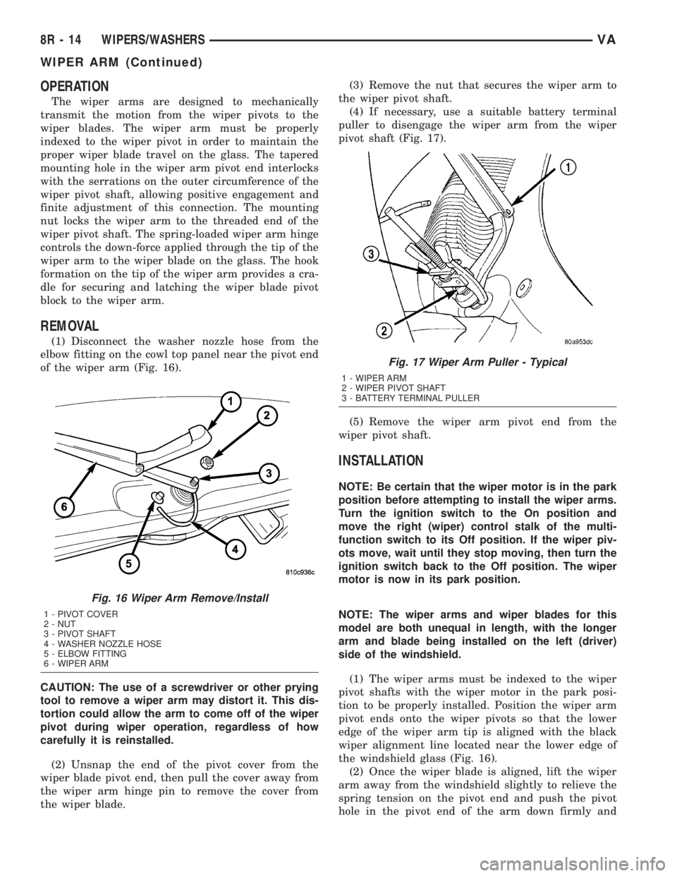
(1) Disconnect the washer nozzle hose from the
elbow fitting on the cowl top panel near the pivot end
of the wiper arm (Fig. 16).
CAUTION: The use of a screwdriver or other prying
tool to remove a wiper arm may distort it. This dis-
tortion could allow the arm to come off of the wiper
pivot during wiper operation, regardless of how
carefully it is reinstalled.
(2) Unsnap the end of the pivot cover from the
wiper blade pivot end, then pull the cover away from
the wiper arm hinge pin to remove the cover from
the wiper blade.(3) Remove the nut that secures the wiper arm to
the wiper pivot shaft.
(4) If necessary, use a suitable battery terminal
puller to disengage the wiper arm from the wiper
pivot shaft (Fig. 17).
(5) Remove the wiper arm pivot end from the
wiper pivot shaft.
INSTALLATION
NOTE: Be certain that the wiper motor is in the park
position before attempting to install the wiper arms.
Turn the ignition switch to the On position and
move the right (wiper) control stalk of the multi-
function switch to its Off position. If the wiper piv-
ots move, wait until they stop moving, then turn the
ignition switch back to the Off position. The wiper
motor is now in its park position.
NOTE: The wiper arms and wiper blades for this
model are both unequal in length, with the longer
arm and blade being installed on the left (driver)
side of the windshield.
(1) The wiper arms must be indexed to the wiper
pivot shafts with the wiper motor in the park posi-
tion to be properly installed. Position the wiper arm
pivot ends onto the wiper pivots so that the lower
edge of the wiper arm tip is aligned with the black
wiper alignment line located near the lower edge of
the windshield glass (Fig. 16).
(2) Once the wiper blade is aligned, lift the wiper
arm away from the windshield slightly to relieve the
spring tension on the pivot end and push the pivot
hole in the pivot end of the arm down firmly and
Fig. 16 Wiper Arm Remove/Install
1 - PIVOT COVER
2 - NUT
3 - PIVOT SHAFT
4 - WASHER NOZZLE HOSE
5 - ELBOW FITTING
6 - WIPER ARM
Fig. 17 Wiper Arm Puller - Typical
1 - WIPER ARM
2 - WIPER PIVOT SHAFT
3 - BATTERY TERMINAL PULLER
8R - 14 WIPERS/WASHERSVA
WIPER ARM (Continued)
Page 297 of 1232
evenly over the wiper pivot shaft. Gently lower the
wiper arm until the wiper blade rests on the glass.
(3) Install and tighten the nut that secures the
wiper arm to the wiper pivot shaft. Tighten the nut
to 24 N´m (18 ft. lbs.).
(4) Wet the windshield glass, then operate the wip-
ers. Move the right (wiper) control stalk of the multi-
function switch to the Off position, then check for the
correct wiper arm position and readjust as required.
(5) Engage the pivot cover with the wiper arm
hinge pin, then push the pivot end of the cover down
firmly and evenly until it snaps over the wiper blade
pivot end.
(6) Reconnect the washer nozzle hose to the elbow
fitting on the cowl top panel near the pivot end of the
wiper arm.
WIPER BLADE
DESCRIPTION
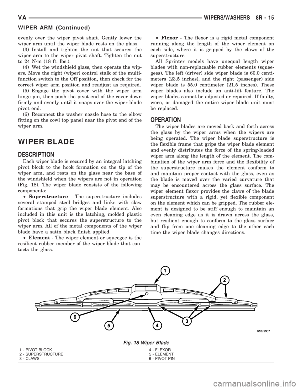
Each wiper blade is secured by an integral latching
pivot block to the hook formation on the tip of the
wiper arm, and rests on the glass near the base of
the windshield when the wipers are not in operation
(Fig. 18). The wiper blade consists of the following
components:
²Superstructure- The superstructure includes
several stamped steel bridges and links with claw
formations that grip the wiper blade element. Also
included in this unit is the latching, molded plastic
pivot block that secures the superstructure to the
wiper arm. All of the metal components of the wiper
blade have a satin black finish applied.
²Element- The wiper element or squeegee is the
resilient rubber member of the wiper blade that con-
tacts the glass.²Flexor- The flexor is a rigid metal component
running along the length of the wiper element on
each side, where it is gripped by the claws of the
superstructure.
All Sprinter models have unequal length wiper
blades with non-replaceable rubber elements (squee-
gees). The left (driver) side wiper blade is 60.0 centi-
meters (23.5 inches), and the right (passenger) side
wiper blade is 55.0 centimeter (21.5 inches). These
wiper blades also include an anti-lift feature. The
wiper blades cannot be adjusted or repaired. If faulty,
worn, or damaged the entire wiper blade unit must
be replaced.
OPERATION
The wiper blades are moved back and forth across
the glass by the wiper arms when the wipers are
being operated. The wiper blade superstructure is
the flexible frame that grips the wiper blade element
and evenly distributes the force of the spring-loaded
wiper arm along the length of the element. The com-
bination of the wiper arm force and the flexibility of
the superstructure makes the element conform to
and maintain proper contact with the glass, even as
the blade is moved over the varied curvature that
may be encountered across the glass surface. The
wiper element flexor provides the claws of the blade
superstructure with a rigid, yet flexible component
on the element which can be gripped. The rubber ele-
ment is designed to be stiff enough to maintain an
even cleaning edge as it is drawn across the glass,
but resilient enough to conform to the glass surface
and flip from one cleaning edge to the other each
time the wiper blade changes directions.
Fig. 18 Wiper Blade
1 - PIVOT BLOCK 4 - FLEXOR
2 - SUPERSTRUCTURE 5 - ELEMENT
3 - CLAWS 6 - PIVOT PIN
VAWIPERS/WASHERS 8R - 15
WIPER ARM (Continued)
Page 298 of 1232
REMOVAL
NOTE: The wiper arms and wiper blades for this
model are both unequal in length, with the longer
arm and blade being installed on the left (driver)
side of the windshield.
(1) Turn the wiper control knob on the end of the
multi-function switch control stalk to the On posi-
tion. Cycle the wiper blades to a convenient working
location on the windshield by turning the ignition
switch to the On and Off positions.
(2) Lift the wiper arm to raise the wiper blade and
element off of the glass, until the wiper arm hinge is
in its over-center position.
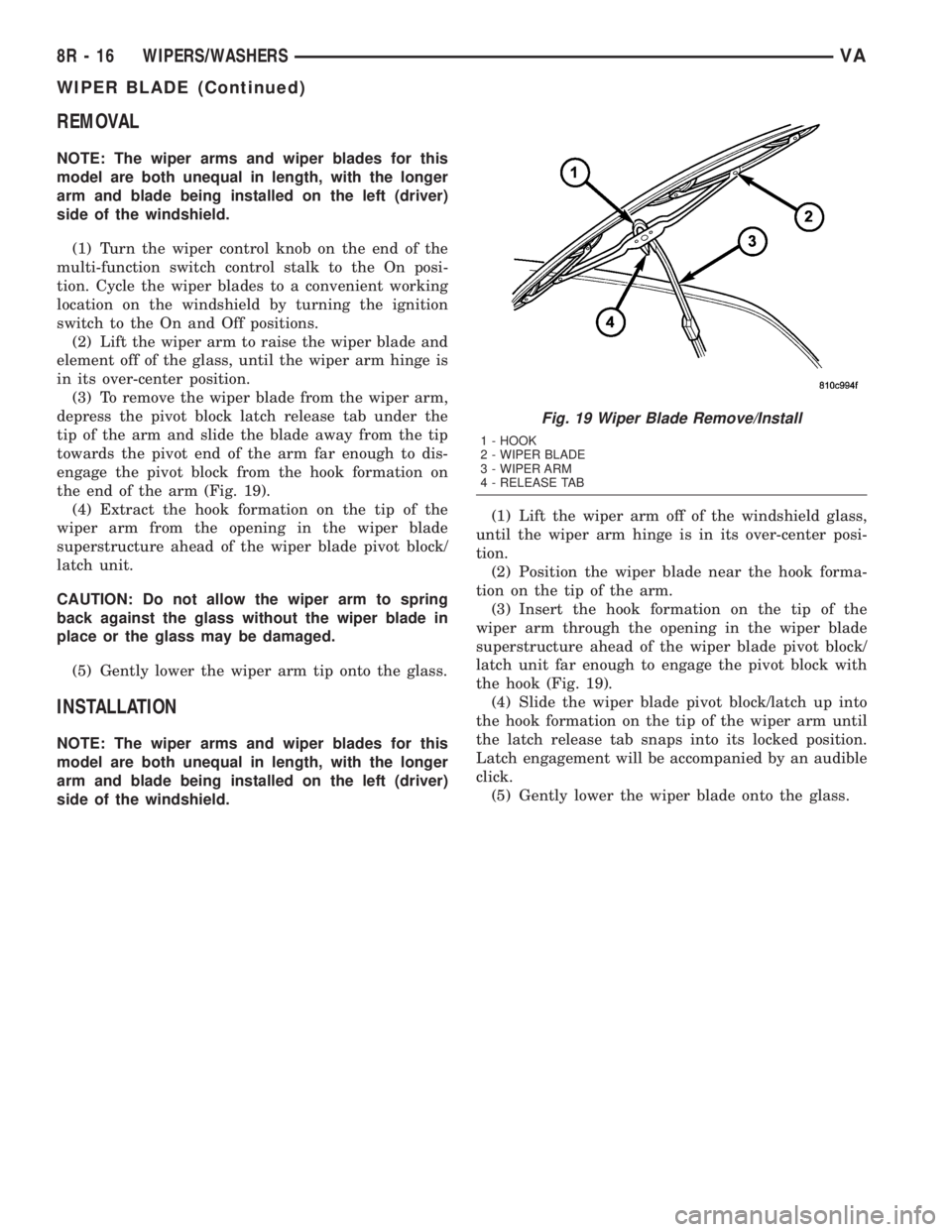
(3) To remove the wiper blade from the wiper arm,
depress the pivot block latch release tab under the
tip of the arm and slide the blade away from the tip
towards the pivot end of the arm far enough to dis-
engage the pivot block from the hook formation on
the end of the arm (Fig. 19).
(4) Extract the hook formation on the tip of the
wiper arm from the opening in the wiper blade
superstructure ahead of the wiper blade pivot block/
latch unit.
CAUTION: Do not allow the wiper arm to spring
back against the glass without the wiper blade in
place or the glass may be damaged.
(5) Gently lower the wiper arm tip onto the glass.
INSTALLATION
NOTE: The wiper arms and wiper blades for this
model are both unequal in length, with the longer
arm and blade being installed on the left (driver)
side of the windshield.(1) Lift the wiper arm off of the windshield glass,
until the wiper arm hinge is in its over-center posi-
tion.
(2) Position the wiper blade near the hook forma-
tion on the tip of the arm.
(3) Insert the hook formation on the tip of the
wiper arm through the opening in the wiper blade
superstructure ahead of the wiper blade pivot block/
latch unit far enough to engage the pivot block with
the hook (Fig. 19).
(4) Slide the wiper blade pivot block/latch up into
the hook formation on the tip of the wiper arm until
the latch release tab snaps into its locked position.
Latch engagement will be accompanied by an audible
click.
(5) Gently lower the wiper blade onto the glass.
Fig. 19 Wiper Blade Remove/Install
1 - HOOK
2 - WIPER BLADE
3 - WIPER ARM
4 - RELEASE TAB
8R - 16 WIPERS/WASHERSVA
WIPER BLADE (Continued)
Page 299 of 1232
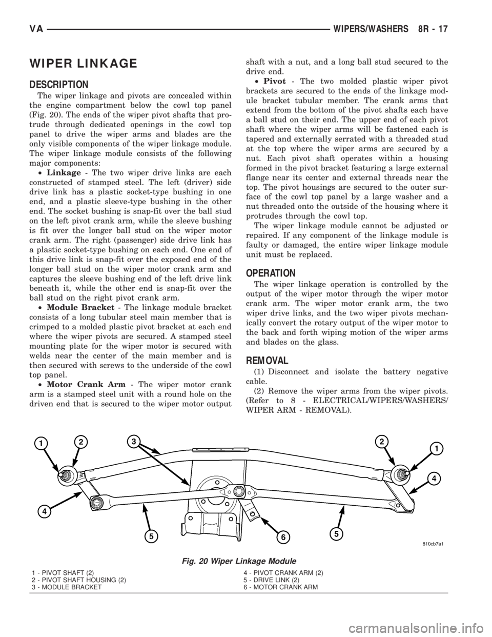
WIPER LINKAGE
DESCRIPTION
The wiper linkage and pivots are concealed within
the engine compartment below the cowl top panel
(Fig. 20). The ends of the wiper pivot shafts that pro-
trude through dedicated openings in the cowl top
panel to drive the wiper arms and blades are the
only visible components of the wiper linkage module.
The wiper linkage module consists of the following
major components:
²Linkage- The two wiper drive links are each
constructed of stamped steel. The left (driver) side
drive link has a plastic socket-type bushing in one
end, and a plastic sleeve-type bushing in the other
end. The socket bushing is snap-fit over the ball stud
on the left pivot crank arm, while the sleeve bushing
is fit over the longer ball stud on the wiper motor
crank arm. The right (passenger) side drive link has
a plastic socket-type bushing on each end. One end of
this drive link is snap-fit over the exposed end of the
longer ball stud on the wiper motor crank arm and
captures the sleeve bushing end of the left drive link
beneath it, while the other end is snap-fit over the
ball stud on the right pivot crank arm.
²Module Bracket- The linkage module bracket
consists of a long tubular steel main member that is
crimped to a molded plastic pivot bracket at each end
where the wiper pivots are secured. A stamped steel
mounting plate for the wiper motor is secured with
welds near the center of the main member and is
then secured with screws to the underside of the cowl
top panel.
²Motor Crank Arm- The wiper motor crank
arm is a stamped steel unit with a round hole on the
driven end that is secured to the wiper motor outputshaft with a nut, and a long ball stud secured to the
drive end.
²Pivot- The two molded plastic wiper pivot
brackets are secured to the ends of the linkage mod-
ule bracket tubular member. The crank arms that
extend from the bottom of the pivot shafts each have
a ball stud on their end. The upper end of each pivot
shaft where the wiper arms will be fastened each is
tapered and externally serrated with a threaded stud
at the top where the wiper arms are secured by a
nut. Each pivot shaft operates within a housing
formed in the pivot bracket featuring a large external
flange near its center and external threads near the
top. The pivot housings are secured to the outer sur-
face of the cowl top panel by a large washer and a
nut threaded onto the outside of the housing where it
protrudes through the cowl top.
The wiper linkage module cannot be adjusted or
repaired. If any component of the linkage module is
faulty or damaged, the entire wiper linkage module
unit must be replaced.
OPERATION
The wiper linkage operation is controlled by the
output of the wiper motor through the wiper motor
crank arm. The wiper motor crank arm, the two
wiper drive links, and the two wiper pivots mechan-
ically convert the rotary output of the wiper motor to
the back and forth wiping motion of the wiper arms
and blades on the glass.
REMOVAL
(1) Disconnect and isolate the battery negative
cable.
(2) Remove the wiper arms from the wiper pivots.
(Refer to 8 - ELECTRICAL/WIPERS/WASHERS/
WIPER ARM - REMOVAL).
Fig. 20 Wiper Linkage Module
1 - PIVOT SHAFT (2) 4 - PIVOT CRANK ARM (2)
2 - PIVOT SHAFT HOUSING (2) 5 - DRIVE LINK (2)
3 - MODULE BRACKET 6 - MOTOR CRANK ARM
VAWIPERS/WASHERS 8R - 17
Page 300 of 1232
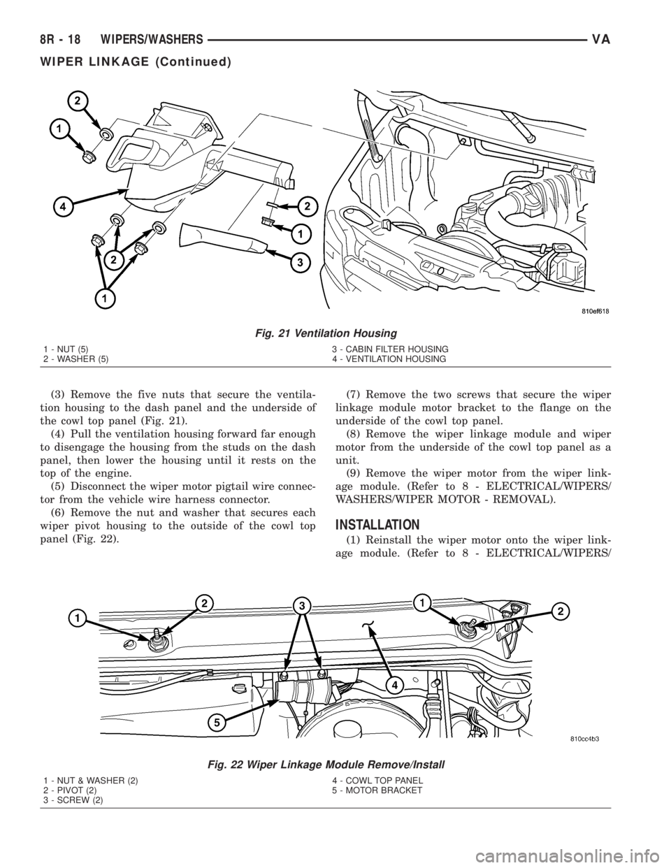
(3) Remove the five nuts that secure the ventila-
tion housing to the dash panel and the underside of
the cowl top panel (Fig. 21).
(4) Pull the ventilation housing forward far enough
to disengage the housing from the studs on the dash
panel, then lower the housing until it rests on the
top of the engine.
(5) Disconnect the wiper motor pigtail wire connec-
tor from the vehicle wire harness connector.
(6) Remove the nut and washer that secures each
wiper pivot housing to the outside of the cowl top
panel (Fig. 22).(7) Remove the two screws that secure the wiper
linkage module motor bracket to the flange on the
underside of the cowl top panel.
(8) Remove the wiper linkage module and wiper
motor from the underside of the cowl top panel as a
unit.
(9) Remove the wiper motor from the wiper link-
age module. (Refer to 8 - ELECTRICAL/WIPERS/
WASHERS/WIPER MOTOR - REMOVAL).
INSTALLATION
(1) Reinstall the wiper motor onto the wiper link-
age module. (Refer to 8 - ELECTRICAL/WIPERS/
Fig. 21 Ventilation Housing
1 - NUT (5) 3 - CABIN FILTER HOUSING
2 - WASHER (5) 4 - VENTILATION HOUSING
Fig. 22 Wiper Linkage Module Remove/Install
1 - NUT & WASHER (2) 4 - COWL TOP PANEL
2 - PIVOT (2) 5 - MOTOR BRACKET
3 - SCREW (2)
8R - 18 WIPERS/WASHERSVA
WIPER LINKAGE (Continued)