MERCEDES-BENZ SPRINTER 2005 Service Repair Manual
Manufacturer: MERCEDES-BENZ, Model Year: 2005, Model line: SPRINTER, Model: MERCEDES-BENZ SPRINTER 2005Pages: 1232, PDF Size: 39.23 MB
Page 271 of 1232
SEAT BELT TURNING LOOP
ADJUSTER
REMOVAL
WARNING: ON VEHICLES EQUIPPED WITH AIR-
BAGS, DISABLE THE SUPPLEMENTAL RESTRAINT
SYSTEM BEFORE ATTEMPTING ANY STEERING
WHEEL, STEERING COLUMN, DRIVER AIRBAG,
PASSENGER AIRBAG, SEAT BELT TENSIONER, OR
INSTRUMENT PANEL COMPONENT DIAGNOSIS OR
SERVICE. DISCONNECT AND ISOLATE THE BAT-
TERY NEGATIVE (GROUND) CABLE, THEN WAIT
TWO MINUTES FOR THE SYSTEM CAPACITOR TO
DISCHARGE BEFORE PERFORMING FURTHER
DIAGNOSIS OR SERVICE. THIS IS THE ONLY SURE
WAY TO DISABLE THE SUPPLEMENTAL
RESTRAINT SYSTEM. FAILURE TO TAKE THE
PROPER PRECAUTIONS COULD RESULT IN ACCI-
DENTAL AIRBAG DEPLOYMENT AND POSSIBLE
PERSONAL INJURY.
WARNING: DURING AND FOLLOWING ANY SEAT
BELT SERVICE, CAREFULLY INSPECT ALL SEAT
BELTS, BUCKLES, MOUNTING HARDWARE,
RETRACTORS, AND ANCHORS FOR PROPER
INSTALLATION, OPERATION, OR DAMAGE.
REPLACE ANY BELT THAT IS CUT, FRAYED, OR
TORN. STRAIGHTEN ANY BELT THAT IS TWISTED.
TIGHTEN ANY LOOSE FASTENERS. REPLACE ANY
BELT THAT HAS A DAMAGED OR INOPERATIVE
BUCKLE OR RETRACTOR. REPLACE ANY BELT
THAT HAS A BENT OR DAMAGED LATCH PLATE
OR ANCHOR PLATE. NEVER ATTEMPT TO REPAIR
A SEAT BELT COMPONENT. ALWAYS REPLACE
DAMAGED OR FAULTY SEAT BELT COMPONENTS
WITH THE CORRECT, NEW AND UNUSED
REPLACEMENT PARTS LISTED IN THE
DAIMLERCHRYSLER MOPAR PARTS CATALOG.
(1) Move the front seat to its most forward position
for easiest access to the B-pillar trim.
(2) Disconnect and isolate the battery negative
cable. Wait two minutes for the system capacitor to
discharge before further service.
(3) Remove the trim panel from the inside of the
B-pillar. (Refer to 23 - BODY/INTERIOR/B-PILLAR
TRIM - REMOVAL).
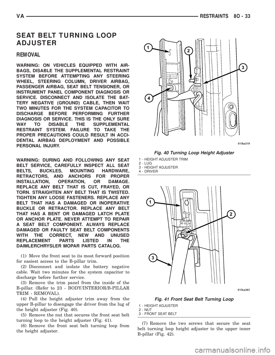
(4) Pull the height adjuster trim away from the
upper B-pillar to disengage the driver from the lug of
the height adjuster (Fig. 40).
(5) Remove the nut that secures the front seat belt
turning loop to the height adjuster (Fig. 41).
(6) Remove the front seat belt turning loop from
the height adjuster.(7) Remove the two screws that secure the seat
belt turning loop height adjuster to the upper inner
B-pillar (Fig. 42).
Fig. 40 Turning Loop Height Adjuster
1 - HEIGHT ADJUSTER TRIM
2 - LUG
3 - HEIGHT ADJUSTER
4 - DRIVER
Fig. 41 Front Seat Belt Turning Loop
1 - HEIGHT ADJUSTER
2 - NUT
3 - FRONT SEAT BELT
VARESTRAINTS 8O - 33
Page 272 of 1232
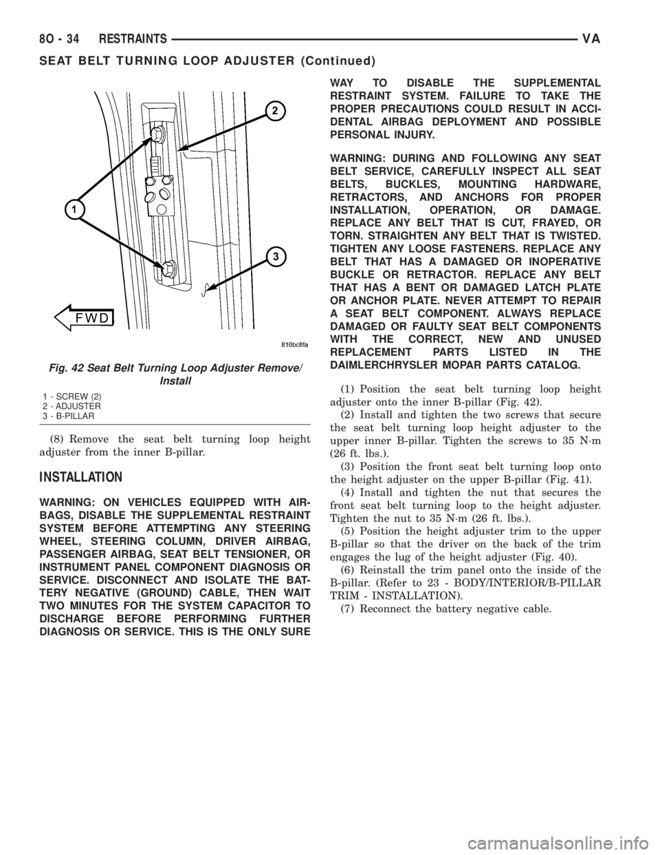
(8) Remove the seat belt turning loop height
adjuster from the inner B-pillar.
INSTALLATION
WARNING: ON VEHICLES EQUIPPED WITH AIR-
BAGS, DISABLE THE SUPPLEMENTAL RESTRAINT
SYSTEM BEFORE ATTEMPTING ANY STEERING
WHEEL, STEERING COLUMN, DRIVER AIRBAG,
PASSENGER AIRBAG, SEAT BELT TENSIONER, OR
INSTRUMENT PANEL COMPONENT DIAGNOSIS OR
SERVICE. DISCONNECT AND ISOLATE THE BAT-
TERY NEGATIVE (GROUND) CABLE, THEN WAIT
TWO MINUTES FOR THE SYSTEM CAPACITOR TO
DISCHARGE BEFORE PERFORMING FURTHER
DIAGNOSIS OR SERVICE. THIS IS THE ONLY SUREWAY TO DISABLE THE SUPPLEMENTAL
RESTRAINT SYSTEM. FAILURE TO TAKE THE
PROPER PRECAUTIONS COULD RESULT IN ACCI-
DENTAL AIRBAG DEPLOYMENT AND POSSIBLE
PERSONAL INJURY.
WARNING: DURING AND FOLLOWING ANY SEAT
BELT SERVICE, CAREFULLY INSPECT ALL SEAT
BELTS, BUCKLES, MOUNTING HARDWARE,
RETRACTORS, AND ANCHORS FOR PROPER
INSTALLATION, OPERATION, OR DAMAGE.
REPLACE ANY BELT THAT IS CUT, FRAYED, OR
TORN. STRAIGHTEN ANY BELT THAT IS TWISTED.
TIGHTEN ANY LOOSE FASTENERS. REPLACE ANY
BELT THAT HAS A DAMAGED OR INOPERATIVE
BUCKLE OR RETRACTOR. REPLACE ANY BELT
THAT HAS A BENT OR DAMAGED LATCH PLATE
OR ANCHOR PLATE. NEVER ATTEMPT TO REPAIR
A SEAT BELT COMPONENT. ALWAYS REPLACE
DAMAGED OR FAULTY SEAT BELT COMPONENTS
WITH THE CORRECT, NEW AND UNUSED
REPLACEMENT PARTS LISTED IN THE
DAIMLERCHRYSLER MOPAR PARTS CATALOG.
(1) Position the seat belt turning loop height
adjuster onto the inner B-pillar (Fig. 42).
(2) Install and tighten the two screws that secure
the seat belt turning loop height adjuster to the
upper inner B-pillar. Tighten the screws to 35 N´m
(26 ft. lbs.).
(3) Position the front seat belt turning loop onto
the height adjuster on the upper B-pillar (Fig. 41).
(4) Install and tighten the nut that secures the
front seat belt turning loop to the height adjuster.
Tighten the nut to 35 N´m (26 ft. lbs.).
(5) Position the height adjuster trim to the upper
B-pillar so that the driver on the back of the trim
engages the lug of the height adjuster (Fig. 40).
(6) Reinstall the trim panel onto the inside of the
B-pillar. (Refer to 23 - BODY/INTERIOR/B-PILLAR
TRIM - INSTALLATION).
(7) Reconnect the battery negative cable.
Fig. 42 Seat Belt Turning Loop Adjuster Remove/
Install
1 - SCREW (2)
2 - ADJUSTER
3 - B-PILLAR
8O - 34 RESTRAINTSVA
SEAT BELT TURNING LOOP ADJUSTER (Continued)
Page 273 of 1232
SPEED CONTROL
TABLE OF CONTENTS
page page
SPEED CONTROL
DESCRIPTION..........................1
OPERATION............................1
SPECIFICATIONS
TORQUE.............................2
CABLE
DESCRIPTION..........................3SERVO
DESCRIPTION..........................3
SWITCH
REMOVAL.............................3
INSTALLATION..........................3
SPEED CONTROL
DESCRIPTION
The speed control system is electronically con-
trolled by the Engine Control Module (ECM).A
cable and a vacuum controlled servo are not
used. This is a servo-less system.Control of the
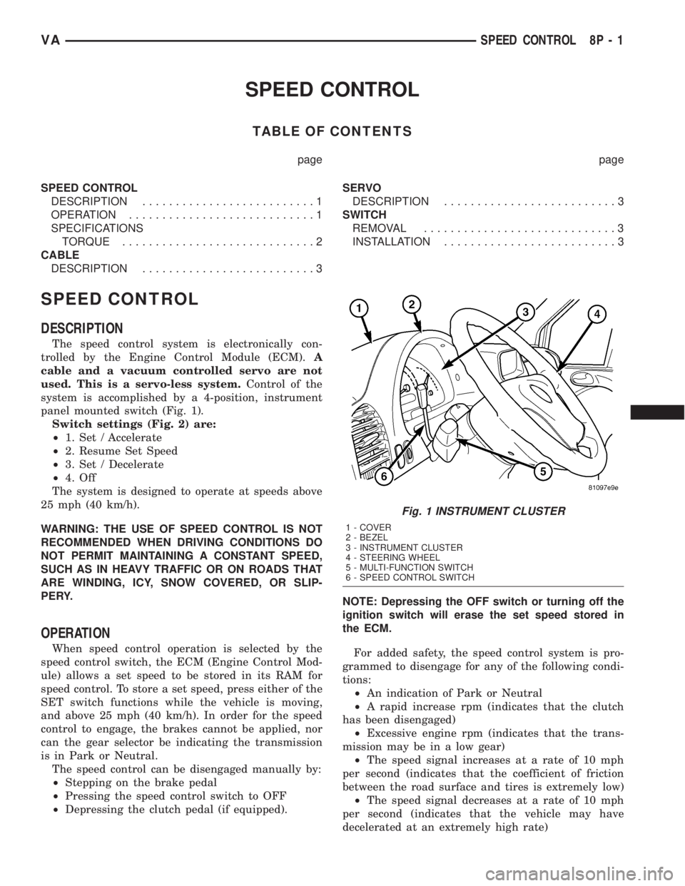
system is accomplished by a 4-position, instrument
panel mounted switch (Fig. 1).
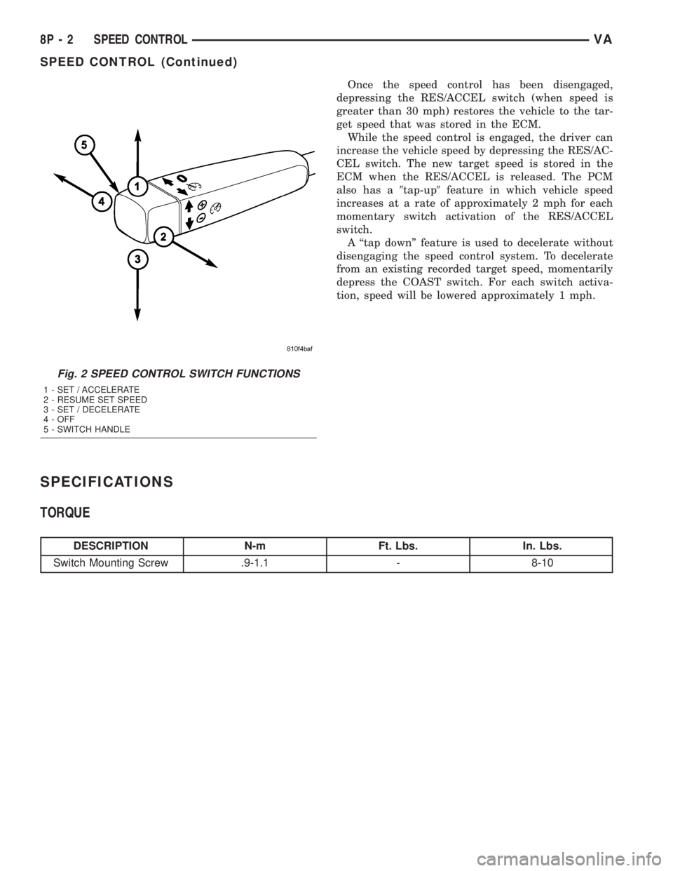
Switch settings (Fig. 2) are:
²1. Set / Accelerate
²2. Resume Set Speed
²3. Set / Decelerate
²4. Off
The system is designed to operate at speeds above
25 mph (40 km/h).
WARNING: THE USE OF SPEED CONTROL IS NOT
RECOMMENDED WHEN DRIVING CONDITIONS DO
NOT PERMIT MAINTAINING A CONSTANT SPEED,
SUCH AS IN HEAVY TRAFFIC OR ON ROADS THAT
ARE WINDING, ICY, SNOW COVERED, OR SLIP-
PERY.
OPERATION
When speed control operation is selected by the
speed control switch, the ECM (Engine Control Mod-
ule) allows a set speed to be stored in its RAM for
speed control. To store a set speed, press either of the
SET switch functions while the vehicle is moving,
and above 25 mph (40 km/h). In order for the speed
control to engage, the brakes cannot be applied, nor
can the gear selector be indicating the transmission
is in Park or Neutral.
The speed control can be disengaged manually by:
²Stepping on the brake pedal
²Pressing the speed control switch to OFF
²Depressing the clutch pedal (if equipped).NOTE: Depressing the OFF switch or turning off the
ignition switch will erase the set speed stored in
the ECM.
For added safety, the speed control system is pro-
grammed to disengage for any of the following condi-
tions:
²An indication of Park or Neutral
²A rapid increase rpm (indicates that the clutch
has been disengaged)
²Excessive engine rpm (indicates that the trans-
mission may be in a low gear)
²The speed signal increases at a rate of 10 mph
per second (indicates that the coefficient of friction
between the road surface and tires is extremely low)
²The speed signal decreases at a rate of 10 mph
per second (indicates that the vehicle may have
decelerated at an extremely high rate)
Fig. 1 INSTRUMENT CLUSTER
1 - COVER
2 - BEZEL
3 - INSTRUMENT CLUSTER
4 - STEERING WHEEL
5 - MULTI-FUNCTION SWITCH
6 - SPEED CONTROL SWITCH
VASPEED CONTROL 8P - 1
Page 274 of 1232
Once the speed control has been disengaged,
depressing the RES/ACCEL switch (when speed is
greater than 30 mph) restores the vehicle to the tar-
get speed that was stored in the ECM.
While the speed control is engaged, the driver can
increase the vehicle speed by depressing the RES/AC-
CEL switch. The new target speed is stored in the
ECM when the RES/ACCEL is released. The PCM
also has a9tap-up9feature in which vehicle speed
increases at a rate of approximately 2 mph for each
momentary switch activation of the RES/ACCEL
switch.
A ªtap downº feature is used to decelerate without
disengaging the speed control system. To decelerate
from an existing recorded target speed, momentarily
depress the COAST switch. For each switch activa-
tion, speed will be lowered approximately 1 mph.
SPECIFICATIONS
TORQUE
DESCRIPTION N-m Ft. Lbs. In. Lbs.
Switch Mounting Screw .9-1.1 - 8-10
Fig. 2 SPEED CONTROL SWITCH FUNCTIONS
1 - SET / ACCELERATE
2 - RESUME SET SPEED
3 - SET / DECELERATE
4 - OFF
5 - SWITCH HANDLE
8P - 2 SPEED CONTROLVA
SPEED CONTROL (Continued)
Page 275 of 1232

CABLE
DESCRIPTION
A cable and a vacuum controlled servo are not used
with this package. This is a cable-less, servo-less sys-
tem. The speed control system is electronically con-
trolled by the Engine Control Module (ECM).
SERVO
DESCRIPTION
A vacuum controlled servo and control cable are
not used with this package. This is a cable-less, ser-
vo-less system. The speed control system is electron-
ically controlled by the Engine Control Module
(ECM).
SWITCH
REMOVAL
The speed control switch is mounted to the back of
the multi-function switch (Fig. 3). The multi-function
switch must be removed first to gain access to the
speed control switch mounting screw.
(1) Remove and isolate negative battery cable from
battery.
(2) Remove multi-function switch. Refer to Multi-
Function Switch Removal/Installation.
(3) Remove switch mounting screw (Fig. 4).
(4) Remove speed control switch from multi-func-
tion switch.
(5) Unplug pigtail electrical connector (Fig. 3) from
instrument panel wiring harness.
INSTALLATION
The speed control switch is mounted to the back of
the multi-function switch (Fig. 3).
(1) Position speed control switch to back of multi-
function switch.
(2) Install switch mounting screw (Fig. 4). Refer to
Torque Specifications.
Install multi-function switch. Refer to Multi-Func-
tion Switch Removal/Installation.
(3) Plug pigtail electrical connector (Fig. 3) into
instrument panel wiring harness. Be sure wires are
not pinched.
(4) Install negative battery cable to battery.
Fig. 3 SPEED CONTROL SWITCH LOCATION
1 - SWITCH HANDLE
2 - PIGTAIL ELECTRICAL CONNECTOR
3 - MULTI-FUNCTION SWITCH
Fig. 4 SPEED CONTROL SWITCH REMOVAL /
INSTALLATION
1 - SWITCH MOUNTING SCREW (1)
2 - SPEED CONTROL SWITCH
3 - SWITCH HANDLE
4 - MULTI-FUNCTION SWITCH
VASPEED CONTROL 8P - 3
Page 276 of 1232

Page 277 of 1232

VEHICLE THEFT SECURITY
TABLE OF CONTENTS
page page
VEHICLE THEFT SECURITY
DESCRIPTION..........................1
OPERATION............................1
DIAGNOSIS AND TESTING - VEHICLE THEFT
SECURITY............................1
INTRUSION SENSOR
REMOVAL.............................2
INSTALLATION..........................2
SECURITY SYSTEM MODULE
REMOVAL.............................2
INSTALLATION..........................2SENTRY KEY REMOTE ENTRY MODULE
DESCRIPTION..........................2
OPERATION............................3
REMOVAL.............................3
INSTALLATION..........................4
SIREN
REMOVAL.............................4
INSTALLATION..........................4
TRANSPONDER KEY
DESCRIPTION..........................5
OPERATION............................5
VEHICLE THEFT SECURITY
DESCRIPTION
An anti-theft alarm with battery powered horn is
available as an option and includes interior monitor-
ing, anti-tow away protection and rear window mon-
itoring based on the heater wires. The alarm is
automatically activated when the central locking sys-
tem is operated.
The alarm will sound when any of the following
occur:
²A door is opened
²A door is unlocked from inside the vehicle
²The hood is opened
²The vehicle is raised at the front or rear
²The trailer wire harness is disconnected
²Movements inside the vehicle
²The central locking is unlocked by a key at any
other door than the driver's door
The alarm is functional about 30 seconds after the
vehicle is locked using the RKE transmitter or the
key in the driver's door. Activation is indicated by the
indicator lights flashing three times and the warning
lamp flashing in the switch. If persons or animals
remain in the locked vehicle, the operator should
switch off the interior monitor to avoid a false alarm.
OPERATION
The anti-theft alarm is activated/deactivated by
locking/unlocking the vehicle with the remote trans-
mitter or with the key at the driver's door. The key
must be held in the locking position for more than
two seconds. Activation is indicated by the turn sig-
nal lights flashing once. Unlocking the vehicle at one
of the other doors will trigger an alarm.The interior monitoring system included in the
anti-theft alarm is based on ultrasonics and triggers
an alarm if an object intrudes the interior of the
vehicle or if any movement is detected inside the
vehicle. For proper and effective protection, all win-
dows and the sunroof must be closed.
To switch off the interior monitoring system and /
or the anti-tow away protection, a switch with LED
indicator light is provided in the switch panel. An
alarm button enables the operator to trigger an
alarm manually and to lock all doors if they are
closed. Triggering an alarm makes the horn sound
and the turn signals flash until the alarm is switched
off.
The anti-theft alarm control unit includes a gradi-
ent indicator as anti-tow away protection. The gradi-
ent indicator triggers an audible and visual alarm if
the vehicle is lifted (to tow away or to remove the
wheels). The alarm remains effective even if the bat-
tery is disconnected as the horn is powered by its
own battery. The interior monitoring system should
be switched off if people and/or animals are left in
the vehicle.
DIAGNOSIS AND TESTING - VEHICLE THEFT
SECURITY
Any diagnosis of the Vehicle Theft Security
system should begin with the use of the DRB
IIItdiagnostic tool. For information on the use
of the DRB IIIt, refer to the appropriate Diag-
nostic Service Manual.
VAVEHICLE THEFT SECURITY 8Q - 1
Page 278 of 1232
INTRUSION SENSOR
REMOVAL
(1) Disconnect and isolate the battery negative
cable.
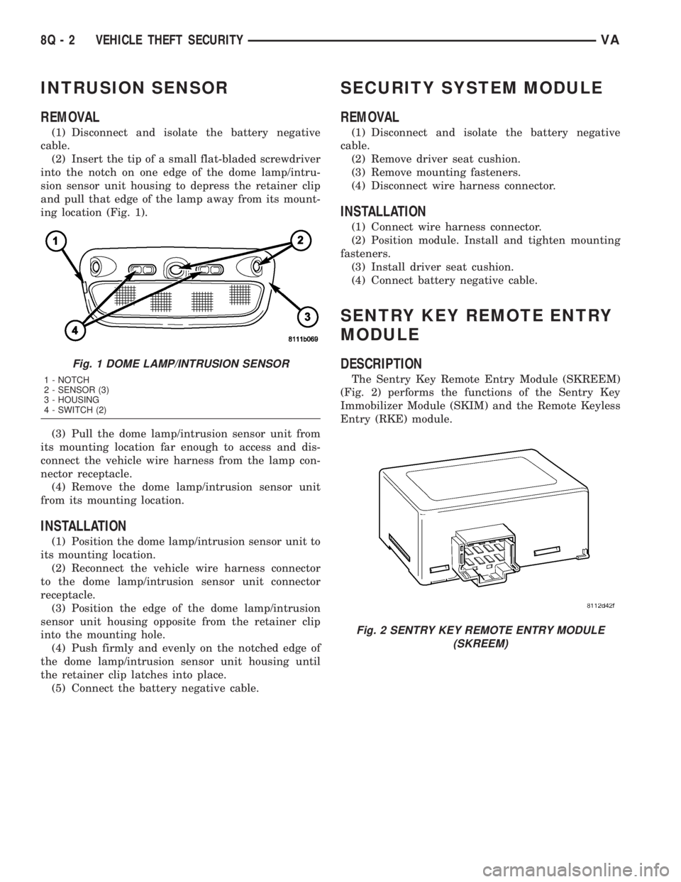
(2) Insert the tip of a small flat-bladed screwdriver
into the notch on one edge of the dome lamp/intru-
sion sensor unit housing to depress the retainer clip
and pull that edge of the lamp away from its mount-
ing location (Fig. 1).
(3) Pull the dome lamp/intrusion sensor unit from
its mounting location far enough to access and dis-
connect the vehicle wire harness from the lamp con-
nector receptacle.
(4) Remove the dome lamp/intrusion sensor unit
from its mounting location.
INSTALLATION
(1) Position the dome lamp/intrusion sensor unit to
its mounting location.
(2) Reconnect the vehicle wire harness connector
to the dome lamp/intrusion sensor unit connector
receptacle.
(3) Position the edge of the dome lamp/intrusion
sensor unit housing opposite from the retainer clip
into the mounting hole.
(4) Push firmly and evenly on the notched edge of
the dome lamp/intrusion sensor unit housing until
the retainer clip latches into place.
(5) Connect the battery negative cable.
SECURITY SYSTEM MODULE
REMOVAL
(1) Disconnect and isolate the battery negative
cable.
(2) Remove driver seat cushion.
(3) Remove mounting fasteners.
(4) Disconnect wire harness connector.
INSTALLATION
(1) Connect wire harness connector.
(2) Position module. Install and tighten mounting
fasteners.
(3) Install driver seat cushion.
(4) Connect battery negative cable.
SENTRY KEY REMOTE ENTRY
MODULE
DESCRIPTION
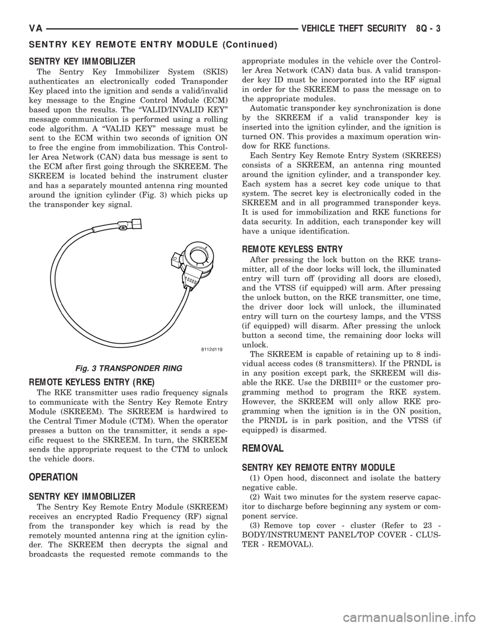
The Sentry Key Remote Entry Module (SKREEM)
(Fig. 2) performs the functions of the Sentry Key
Immobilizer Module (SKIM) and the Remote Keyless
Entry (RKE) module.
Fig. 1 DOME LAMP/INTRUSION SENSOR
1 - NOTCH
2 - SENSOR (3)
3 - HOUSING
4 - SWITCH (2)
Fig. 2 SENTRY KEY REMOTE ENTRY MODULE
(SKREEM)
8Q - 2 VEHICLE THEFT SECURITYVA
Page 279 of 1232
SENTRY KEY IMMOBILIZER
The Sentry Key Immobilizer System (SKIS)
authenticates an electronically coded Transponder
Key placed into the ignition and sends a valid/invalid
key message to the Engine Control Module (ECM)
based upon the results. The ªVALID/INVALID KEYº
message communication is performed using a rolling
code algorithm. A ªVALID KEYº message must be
sent to the ECM within two seconds of ignition ON
to free the engine from immobilization. This Control-
ler Area Network (CAN) data bus message is sent to
the ECM after first going through the SKREEM. The
SKREEM is located behind the instrument cluster
and has a separately mounted antenna ring mounted
around the ignition cylinder (Fig. 3) which picks up
the transponder key signal.
REMOTE KEYLESS ENTRY (RKE)
The RKE transmitter uses radio frequency signals
to communicate with the Sentry Key Remote Entry
Module (SKREEM). The SKREEM is hardwired to
the Central Timer Module (CTM). When the operator
presses a button on the transmitter, it sends a spe-
cific request to the SKREEM. In turn, the SKREEM
sends the appropriate request to the CTM to unlock
the vehicle doors.
OPERATION
SENTRY KEY IMMOBILIZER
The Sentry Key Remote Entry Module (SKREEM)
receives an encrypted Radio Frequency (RF) signal
from the transponder key which is read by the
remotely mounted antenna ring at the ignition cylin-
der. The SKREEM then decrypts the signal and
broadcasts the requested remote commands to theappropriate modules in the vehicle over the Control-
ler Area Network (CAN) data bus. A valid transpon-
der key ID must be incorporated into the RF signal
in order for the SKREEM to pass the message on to
the appropriate modules.
Automatic transponder key synchronization is done
by the SKREEM if a valid transponder key is
inserted into the ignition cylinder, and the ignition is
turned ON. This provides a maximum operation win-
dow for RKE functions.
Each Sentry Key Remote Entry System (SKREES)
consists of a SKREEM, an antenna ring mounted
around the ignition cylinder, and a transponder key.
Each system has a secret key code unique to that
system. The secret key is electronically coded in the
SKREEM and in all programmed transponder keys.
It is used for immobilization and RKE functions for
data security. In addition, each transponder key will
have a unique identification.
REMOTE KEYLESS ENTRY
After pressing the lock button on the RKE trans-
mitter, all of the door locks will lock, the illuminated
entry will turn off (providing all doors are closed),
and the VTSS (if equipped) will arm. After pressing
the unlock button, on the RKE transmitter, one time,
the driver door lock will unlock, the illuminated
entry will turn on the courtesy lamps, and the VTSS
(if equipped) will disarm. After pressing the unlock
button a second time, the remaining door locks will
unlock.
The SKREEM is capable of retaining up to 8 indi-
vidual access codes (8 transmitters). If the PRNDL is
in any position except park, the SKREEM will dis-
able the RKE. Use the DRBIIItor the customer pro-
gramming method to program the RKE system.
However, the SKREEM will only allow RKE pro-
gramming when the ignition is in the ON position,
the PRNDL is in park position, and the VTSS (if
equipped) is disarmed.
REMOVAL
SENTRY KEY REMOTE ENTRY MODULE
(1) Open hood, disconnect and isolate the battery
negative cable.
(2) Wait two minutes for the system reserve capac-
itor to discharge before beginning any system or com-
ponent service.
(3) Remove top cover - cluster (Refer to 23 -
BODY/INSTRUMENT PANEL/TOP COVER - CLUS-
TER - REMOVAL).
Fig. 3 TRANSPONDER RING
VAVEHICLE THEFT SECURITY 8Q - 3
SENTRY KEY REMOTE ENTRY MODULE (Continued)
Page 280 of 1232
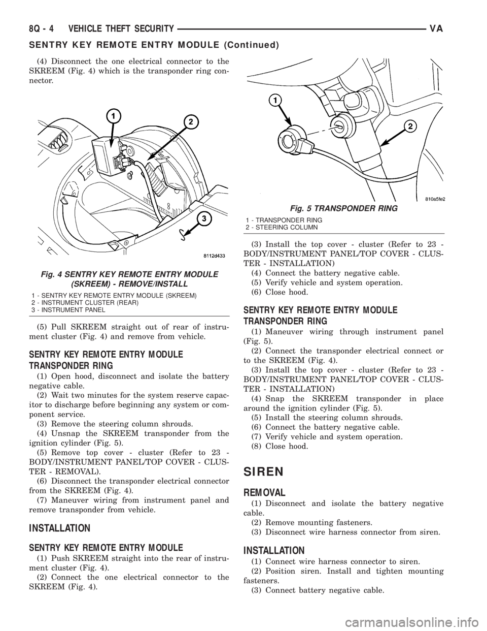
(4) Disconnect the one electrical connector to the
SKREEM (Fig. 4) which is the transponder ring con-
nector.
(5) Pull SKREEM straight out of rear of instru-
ment cluster (Fig. 4) and remove from vehicle.
SENTRY KEY REMOTE ENTRY MODULE
TRANSPONDER RING
(1) Open hood, disconnect and isolate the battery
negative cable.
(2) Wait two minutes for the system reserve capac-
itor to discharge before beginning any system or com-
ponent service.
(3) Remove the steering column shrouds.
(4) Unsnap the SKREEM transponder from the
ignition cylinder (Fig. 5).
(5) Remove top cover - cluster (Refer to 23 -
BODY/INSTRUMENT PANEL/TOP COVER - CLUS-
TER - REMOVAL).
(6) Disconnect the transponder electrical connector
from the SKREEM (Fig. 4).
(7) Maneuver wiring from instrument panel and
remove transponder from vehicle.
INSTALLATION
SENTRY KEY REMOTE ENTRY MODULE
(1) Push SKREEM straight into the rear of instru-
ment cluster (Fig. 4).
(2) Connect the one electrical connector to the
SKREEM (Fig. 4).(3) Install the top cover - cluster (Refer to 23 -
BODY/INSTRUMENT PANEL/TOP COVER - CLUS-
TER - INSTALLATION)
(4) Connect the battery negative cable.
(5) Verify vehicle and system operation.
(6) Close hood.
SENTRY KEY REMOTE ENTRY MODULE
TRANSPONDER RING
(1) Maneuver wiring through instrument panel
(Fig. 5).
(2) Connect the transponder electrical connect or
to the SKREEM (Fig. 4).
(3) Install the top cover - cluster (Refer to 23 -
BODY/INSTRUMENT PANEL/TOP COVER - CLUS-
TER - INSTALLATION)
(4) Snap the SKREEM transponder in place
around the ignition cylinder (Fig. 5).
(5) Install the steering column shrouds.
(6) Connect the battery negative cable.
(7) Verify vehicle and system operation.
(8) Close hood.
SIREN
REMOVAL
(1) Disconnect and isolate the battery negative
cable.
(2) Remove mounting fasteners.
(3) Disconnect wire harness connector from siren.
INSTALLATION
(1) Connect wire harness connector to siren.
(2) Position siren. Install and tighten mounting
fasteners.
(3) Connect battery negative cable.
Fig. 4 SENTRY KEY REMOTE ENTRY MODULE
(SKREEM) - REMOVE/INSTALL
1 - SENTRY KEY REMOTE ENTRY MODULE (SKREEM)
2 - INSTRUMENT CLUSTER (REAR)
3 - INSTRUMENT PANEL
Fig. 5 TRANSPONDER RING
1 - TRANSPONDER RING
2 - STEERING COLUMN
8Q - 4 VEHICLE THEFT SECURITYVA
SENTRY KEY REMOTE ENTRY MODULE (Continued)