MERCEDES-BENZ SPRINTER 2006 Service Manual
Manufacturer: MERCEDES-BENZ, Model Year: 2006, Model line: SPRINTER, Model: MERCEDES-BENZ SPRINTER 2006Pages: 2305, PDF Size: 48.12 MB
Page 121 of 2305
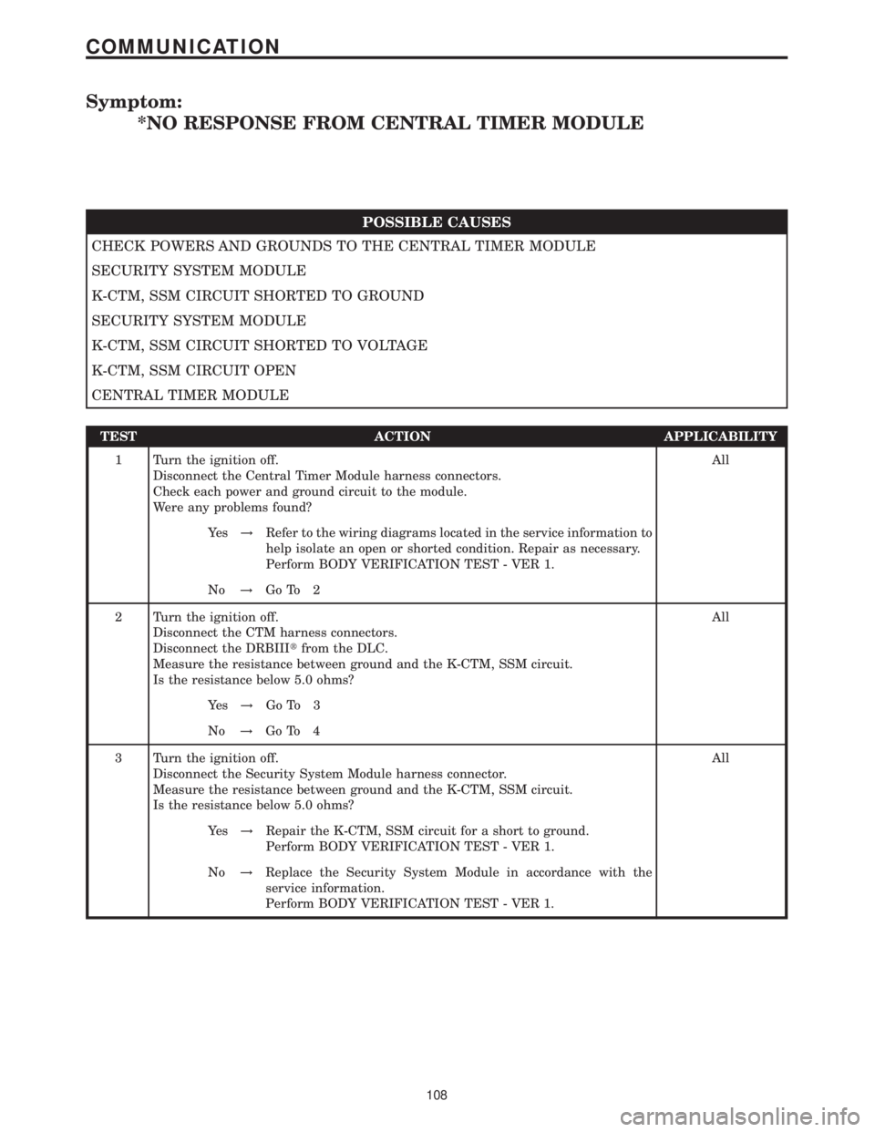
Symptom:
*NO RESPONSE FROM CENTRAL TIMER MODULE
POSSIBLE CAUSES
CHECK POWERS AND GROUNDS TO THE CENTRAL TIMER MODULE
SECURITY SYSTEM MODULE
K-CTM, SSM CIRCUIT SHORTED TO GROUND
SECURITY SYSTEM MODULE
K-CTM, SSM CIRCUIT SHORTED TO VOLTAGE
K-CTM, SSM CIRCUIT OPEN
CENTRAL TIMER MODULE
TEST ACTION APPLICABILITY
1 Turn the ignition off.
Disconnect the Central Timer Module harness connectors.
Check each power and ground circuit to the module.
Were any problems found?All
Ye s!Refer to the wiring diagrams located in the service information to
help isolate an open or shorted condition. Repair as necessary.
Perform BODY VERIFICATION TEST - VER 1.
No!Go To 2
2 Turn the ignition off.
Disconnect the CTM harness connectors.
Disconnect the DRBIIItfrom the DLC.
Measure the resistance between ground and the K-CTM, SSM circuit.
Is the resistance below 5.0 ohms?All
Ye s!Go To 3
No!Go To 4
3 Turn the ignition off.
Disconnect the Security System Module harness connector.
Measure the resistance between ground and the K-CTM, SSM circuit.
Is the resistance below 5.0 ohms?All
Ye s!Repair the K-CTM, SSM circuit for a short to ground.
Perform BODY VERIFICATION TEST - VER 1.
No!Replace the Security System Module in accordance with the
service information.
Perform BODY VERIFICATION TEST - VER 1.
108
COMMUNICATION
Page 122 of 2305
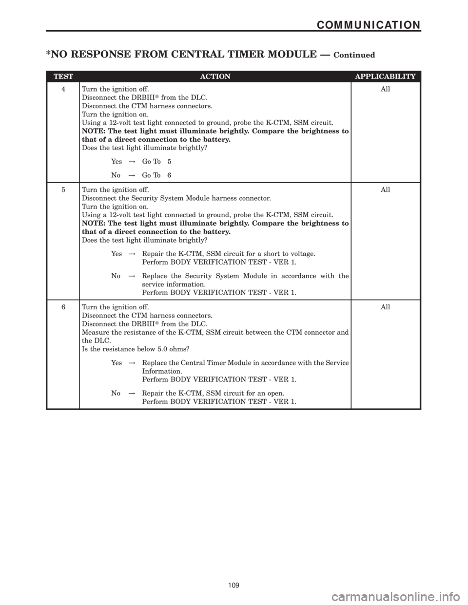
TEST ACTION APPLICABILITY
4 Turn the ignition off.
Disconnect the DRBIIItfrom the DLC.
Disconnect the CTM harness connectors.
Turn the ignition on.
Using a 12-volt test light connected to ground, probe the K-CTM, SSM circuit.
NOTE: The test light must illuminate brightly. Compare the brightness to
that of a direct connection to the battery.
Does the test light illuminate brightly?All
Ye s!Go To 5
No!Go To 6
5 Turn the ignition off.
Disconnect the Security System Module harness connector.
Turn the ignition on.
Using a 12-volt test light connected to ground, probe the K-CTM, SSM circuit.
NOTE: The test light must illuminate brightly. Compare the brightness to
that of a direct connection to the battery.
Does the test light illuminate brightly?All
Ye s!Repair the K-CTM, SSM circuit for a short to voltage.
Perform BODY VERIFICATION TEST - VER 1.
No!Replace the Security System Module in accordance with the
service information.
Perform BODY VERIFICATION TEST - VER 1.
6 Turn the ignition off.
Disconnect the CTM harness connectors.
Disconnect the DRBIIItfrom the DLC.
Measure the resistance of the K-CTM, SSM circuit between the CTM connector and
the DLC.
Is the resistance below 5.0 ohms?All
Ye s!Replace the Central Timer Module in accordance with the Service
Information.
Perform BODY VERIFICATION TEST - VER 1.
No!Repair the K-CTM, SSM circuit for an open.
Perform BODY VERIFICATION TEST - VER 1.
109
COMMUNICATION
*NO RESPONSE FROM CENTRAL TIMER MODULE ÐContinued
Page 123 of 2305
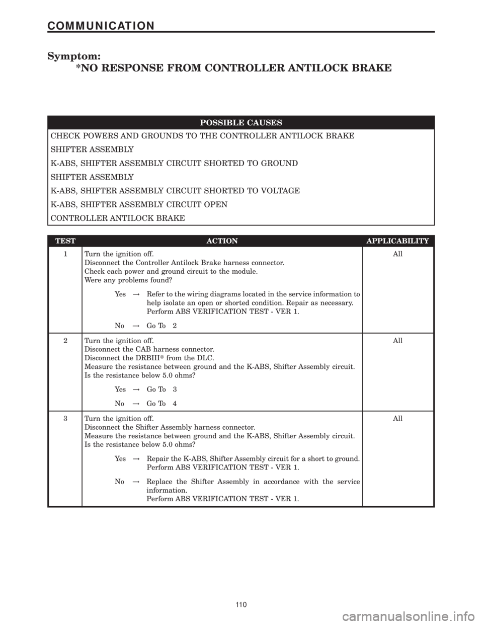
Symptom:
*NO RESPONSE FROM CONTROLLER ANTILOCK BRAKE
POSSIBLE CAUSES
CHECK POWERS AND GROUNDS TO THE CONTROLLER ANTILOCK BRAKE
SHIFTER ASSEMBLY
K-ABS, SHIFTER ASSEMBLY CIRCUIT SHORTED TO GROUND
SHIFTER ASSEMBLY
K-ABS, SHIFTER ASSEMBLY CIRCUIT SHORTED TO VOLTAGE
K-ABS, SHIFTER ASSEMBLY CIRCUIT OPEN
CONTROLLER ANTILOCK BRAKE
TEST ACTION APPLICABILITY
1 Turn the ignition off.
Disconnect the Controller Antilock Brake harness connector.
Check each power and ground circuit to the module.
Were any problems found?All
Ye s!Refer to the wiring diagrams located in the service information to
help isolate an open or shorted condition. Repair as necessary.
Perform ABS VERIFICATION TEST - VER 1.
No!Go To 2
2 Turn the ignition off.
Disconnect the CAB harness connector.
Disconnect the DRBIIItfrom the DLC.
Measure the resistance between ground and the K-ABS, Shifter Assembly circuit.
Is the resistance below 5.0 ohms?All
Ye s!Go To 3
No!Go To 4
3 Turn the ignition off.
Disconnect the Shifter Assembly harness connector.
Measure the resistance between ground and the K-ABS, Shifter Assembly circuit.
Is the resistance below 5.0 ohms?All
Ye s!Repair the K-ABS, Shifter Assembly circuit for a short to ground.
Perform ABS VERIFICATION TEST - VER 1.
No!Replace the Shifter Assembly in accordance with the service
information.
Perform ABS VERIFICATION TEST - VER 1.
11 0
COMMUNICATION
Page 124 of 2305
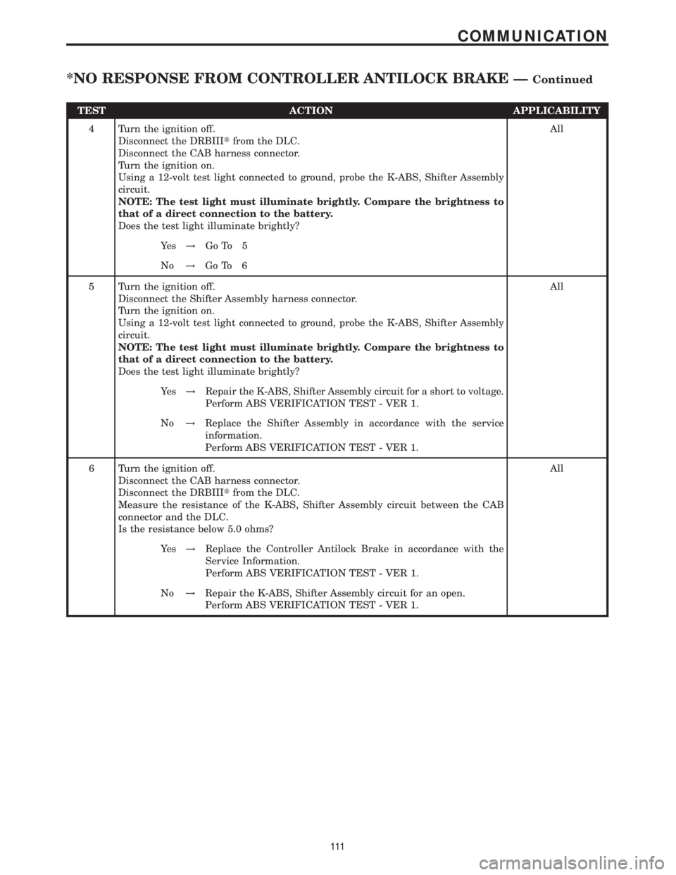
TEST ACTION APPLICABILITY
4 Turn the ignition off.
Disconnect the DRBIIItfrom the DLC.
Disconnect the CAB harness connector.
Turn the ignition on.
Using a 12-volt test light connected to ground, probe the K-ABS, Shifter Assembly
circuit.
NOTE: The test light must illuminate brightly. Compare the brightness to
that of a direct connection to the battery.
Does the test light illuminate brightly?All
Ye s!Go To 5
No!Go To 6
5 Turn the ignition off.
Disconnect the Shifter Assembly harness connector.
Turn the ignition on.
Using a 12-volt test light connected to ground, probe the K-ABS, Shifter Assembly
circuit.
NOTE: The test light must illuminate brightly. Compare the brightness to
that of a direct connection to the battery.
Does the test light illuminate brightly?All
Ye s!Repair the K-ABS, Shifter Assembly circuit for a short to voltage.
Perform ABS VERIFICATION TEST - VER 1.
No!Replace the Shifter Assembly in accordance with the service
information.
Perform ABS VERIFICATION TEST - VER 1.
6 Turn the ignition off.
Disconnect the CAB harness connector.
Disconnect the DRBIIItfrom the DLC.
Measure the resistance of the K-ABS, Shifter Assembly circuit between the CAB
connector and the DLC.
Is the resistance below 5.0 ohms?All
Ye s!Replace the Controller Antilock Brake in accordance with the
Service Information.
Perform ABS VERIFICATION TEST - VER 1.
No!Repair the K-ABS, Shifter Assembly circuit for an open.
Perform ABS VERIFICATION TEST - VER 1.
111
COMMUNICATION
*NO RESPONSE FROM CONTROLLER ANTILOCK BRAKE ÐContinued
Page 125 of 2305
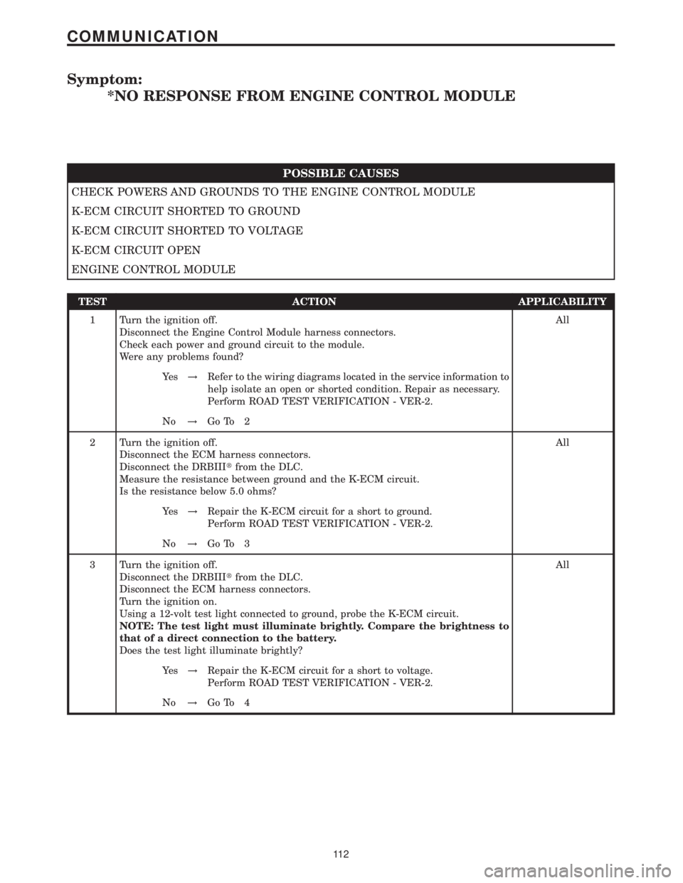
Symptom:
*NO RESPONSE FROM ENGINE CONTROL MODULE
POSSIBLE CAUSES
CHECK POWERS AND GROUNDS TO THE ENGINE CONTROL MODULE
K-ECM CIRCUIT SHORTED TO GROUND
K-ECM CIRCUIT SHORTED TO VOLTAGE
K-ECM CIRCUIT OPEN
ENGINE CONTROL MODULE
TEST ACTION APPLICABILITY
1 Turn the ignition off.
Disconnect the Engine Control Module harness connectors.
Check each power and ground circuit to the module.
Were any problems found?All
Ye s!Refer to the wiring diagrams located in the service information to
help isolate an open or shorted condition. Repair as necessary.
Perform ROAD TEST VERIFICATION - VER-2.
No!Go To 2
2 Turn the ignition off.
Disconnect the ECM harness connectors.
Disconnect the DRBIIItfrom the DLC.
Measure the resistance between ground and the K-ECM circuit.
Is the resistance below 5.0 ohms?All
Ye s!Repair the K-ECM circuit for a short to ground.
Perform ROAD TEST VERIFICATION - VER-2.
No!Go To 3
3 Turn the ignition off.
Disconnect the DRBIIItfrom the DLC.
Disconnect the ECM harness connectors.
Turn the ignition on.
Using a 12-volt test light connected to ground, probe the K-ECM circuit.
NOTE: The test light must illuminate brightly. Compare the brightness to
that of a direct connection to the battery.
Does the test light illuminate brightly?All
Ye s!Repair the K-ECM circuit for a short to voltage.
Perform ROAD TEST VERIFICATION - VER-2.
No!Go To 4
11 2
COMMUNICATION
Page 126 of 2305
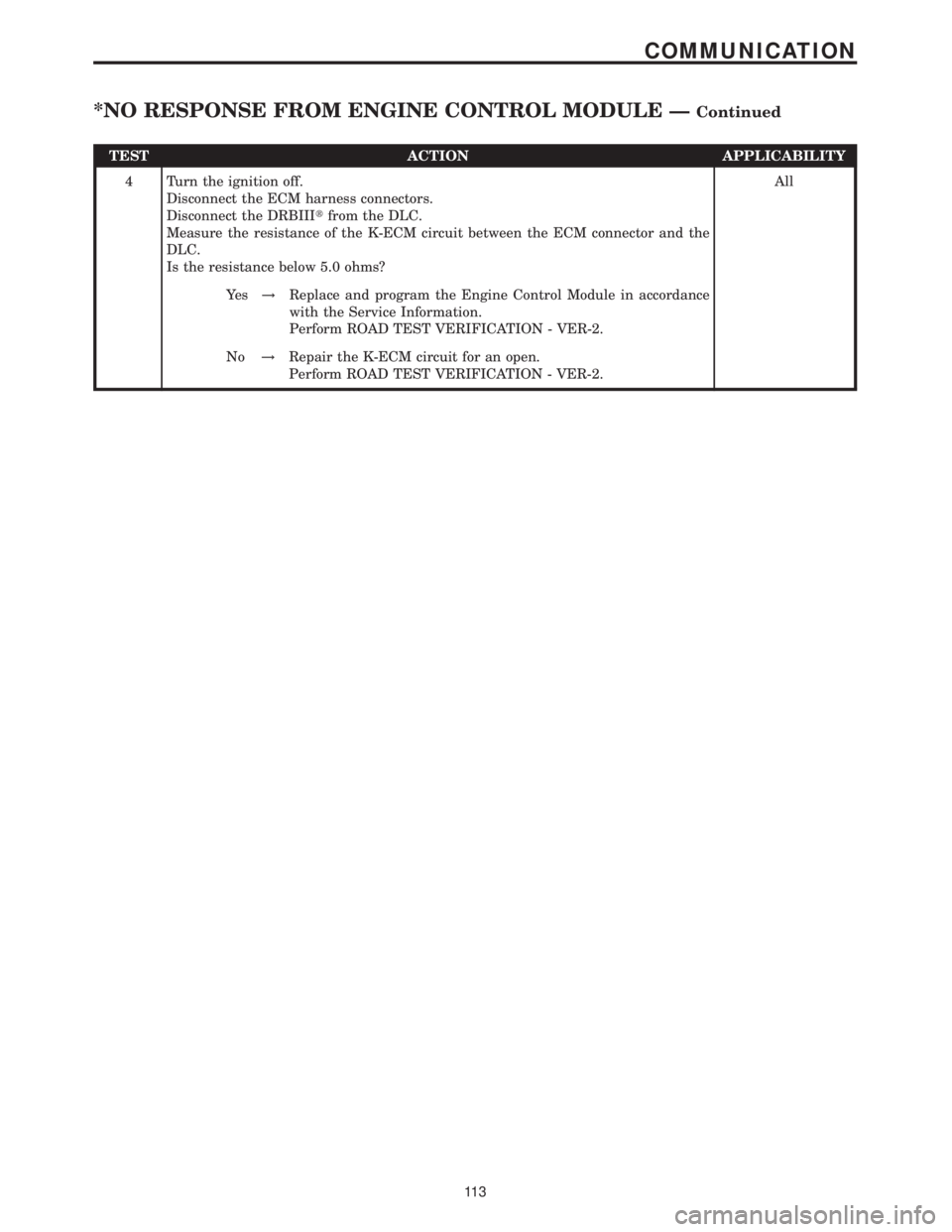
TEST ACTION APPLICABILITY
4 Turn the ignition off.
Disconnect the ECM harness connectors.
Disconnect the DRBIIItfrom the DLC.
Measure the resistance of the K-ECM circuit between the ECM connector and the
DLC.
Is the resistance below 5.0 ohms?All
Ye s!Replace and program the Engine Control Module in accordance
with the Service Information.
Perform ROAD TEST VERIFICATION - VER-2.
No!Repair the K-ECM circuit for an open.
Perform ROAD TEST VERIFICATION - VER-2.
11 3
COMMUNICATION
*NO RESPONSE FROM ENGINE CONTROL MODULE ÐContinued
Page 127 of 2305
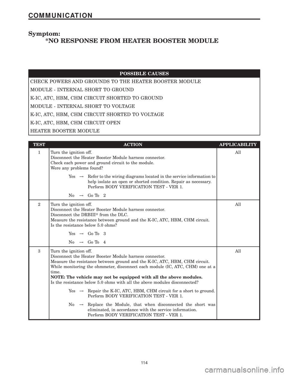
Symptom:
*NO RESPONSE FROM HEATER BOOSTER MODULE
POSSIBLE CAUSES
CHECK POWERS AND GROUNDS TO THE HEATER BOOSTER MODULE
MODULE - INTERNAL SHORT TO GROUND
K-IC, ATC, HBM, CHM CIRCUIT SHORTED TO GROUND
MODULE - INTERNAL SHORT TO VOLTAGE
K-IC, ATC, HBM, CHM CIRCUIT SHORTED TO VOLTAGE
K-IC, ATC, HBM, CHM CIRCUIT OPEN
HEATER BOOSTER MODULE
TEST ACTION APPLICABILITY
1 Turn the ignition off.
Disconnect the Heater Booster Module harness connector.
Check each power and ground circuit to the module.
Were any problems found?All
Ye s!Refer to the wiring diagrams located in the service information to
help isolate an open or shorted condition. Repair as necessary.
Perform BODY VERIFICATION TEST - VER 1.
No!Go To 2
2 Turn the ignition off.
Disconnect the Heater Booster Module harness connector.
Disconnect the DRBIIItfrom the DLC.
Measure the resistance between ground and the K-IC, ATC, HBM, CHM circuit.
Is the resistance below 5.0 ohms?All
Ye s!Go To 3
No!Go To 4
3 Turn the ignition off.
Disconnect the Heater Booster Module harness connector.
Measure the resistance between ground and the K-IC, ATC, HBM, CHM circuit.
While monitoring the ohmmeter, disconnect each module (IC, ATC, CHM) one at a
time.
NOTE: The vehicle may not be equipped with all the above modules.
Is the resistance below 5.0 ohms with all the above modules disconnected?All
Ye s!Repair the K-IC, ATC, HBM, CHM circuit for a short to ground.
Perform BODY VERIFICATION TEST - VER 1.
No!Replace the Module, that when disconnected the short was
eliminated, in accordance with the service information.
Perform BODY VERIFICATION TEST - VER 1.
11 4
COMMUNICATION
Page 128 of 2305
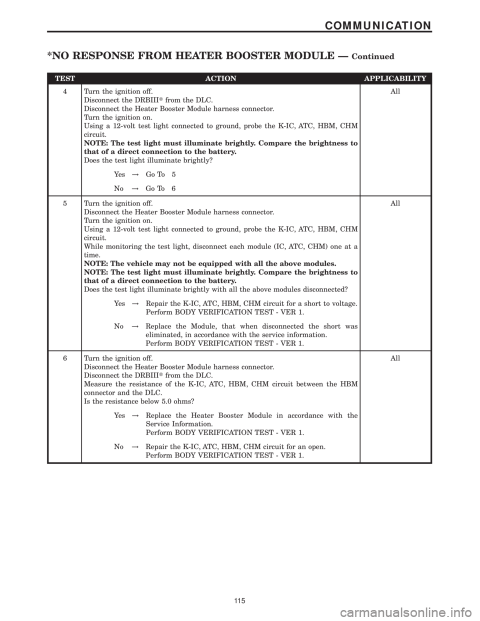
TEST ACTION APPLICABILITY
4 Turn the ignition off.
Disconnect the DRBIIItfrom the DLC.
Disconnect the Heater Booster Module harness connector.
Turn the ignition on.
Using a 12-volt test light connected to ground, probe the K-IC, ATC, HBM, CHM
circuit.
NOTE: The test light must illuminate brightly. Compare the brightness to
that of a direct connection to the battery.
Does the test light illuminate brightly?All
Ye s!Go To 5
No!Go To 6
5 Turn the ignition off.
Disconnect the Heater Booster Module harness connector.
Turn the ignition on.
Using a 12-volt test light connected to ground, probe the K-IC, ATC, HBM, CHM
circuit.
While monitoring the test light, disconnect each module (IC, ATC, CHM) one at a
time.
NOTE: The vehicle may not be equipped with all the above modules.
NOTE: The test light must illuminate brightly. Compare the brightness to
that of a direct connection to the battery.
Does the test light illuminate brightly with all the above modules disconnected?All
Ye s!Repair the K-IC, ATC, HBM, CHM circuit for a short to voltage.
Perform BODY VERIFICATION TEST - VER 1.
No!Replace the Module, that when disconnected the short was
eliminated, in accordance with the service information.
Perform BODY VERIFICATION TEST - VER 1.
6 Turn the ignition off.
Disconnect the Heater Booster Module harness connector.
Disconnect the DRBIIItfrom the DLC.
Measure the resistance of the K-IC, ATC, HBM, CHM circuit between the HBM
connector and the DLC.
Is the resistance below 5.0 ohms?All
Ye s!Replace the Heater Booster Module in accordance with the
Service Information.
Perform BODY VERIFICATION TEST - VER 1.
No!Repair the K-IC, ATC, HBM, CHM circuit for an open.
Perform BODY VERIFICATION TEST - VER 1.
11 5
COMMUNICATION
*NO RESPONSE FROM HEATER BOOSTER MODULE ÐContinued
Page 129 of 2305
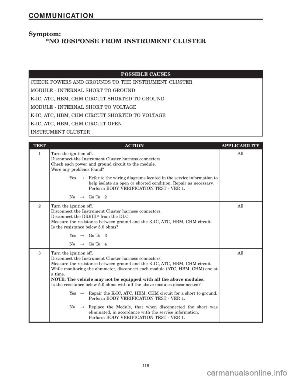
Symptom:
*NO RESPONSE FROM INSTRUMENT CLUSTER
POSSIBLE CAUSES
CHECK POWERS AND GROUNDS TO THE INSTRUMENT CLUSTER
MODULE - INTERNAL SHORT TO GROUND
K-IC, ATC, HBM, CHM CIRCUIT SHORTED TO GROUND
MODULE - INTERNAL SHORT TO VOLTAGE
K-IC, ATC, HBM, CHM CIRCUIT SHORTED TO VOLTAGE
K-IC, ATC, HBM, CHM CIRCUIT OPEN
INSTRUMENT CLUSTER
TEST ACTION APPLICABILITY
1 Turn the ignition off.
Disconnect the Instrument Cluster harness connectors.
Check each power and ground circuit to the module.
Were any problems found?All
Ye s!Refer to the wiring diagrams located in the service information to
help isolate an open or shorted condition. Repair as necessary.
Perform BODY VERIFICATION TEST - VER 1.
No!Go To 2
2 Turn the ignition off.
Disconnect the Instrument Cluster harness connectors.
Disconnect the DRBIIItfrom the DLC.
Measure the resistance between ground and the K-IC, ATC, HBM, CHM circuit.
Is the resistance below 5.0 ohms?All
Ye s!Go To 3
No!Go To 4
3 Turn the ignition off.
Disconnect the Instrument Cluster harness connectors.
Measure the resistance between ground and the K-IC, ATC, HBM, CHM circuit.
While monitoring the ohmmeter, disconnect each module (ATC, HBM, CHM) one at
a time.
NOTE: The vehicle may not be equipped with all the above modules.
Is the resistance below 5.0 ohms with all the above modules disconnected?All
Ye s!Repair the K-IC, ATC, HBM, CHM circuit for a short to ground.
Perform BODY VERIFICATION TEST - VER 1.
No!Replace the Module, that when disconnected the short was
eliminated, in accordance with the service information.
Perform BODY VERIFICATION TEST - VER 1.
11 6
COMMUNICATION
Page 130 of 2305
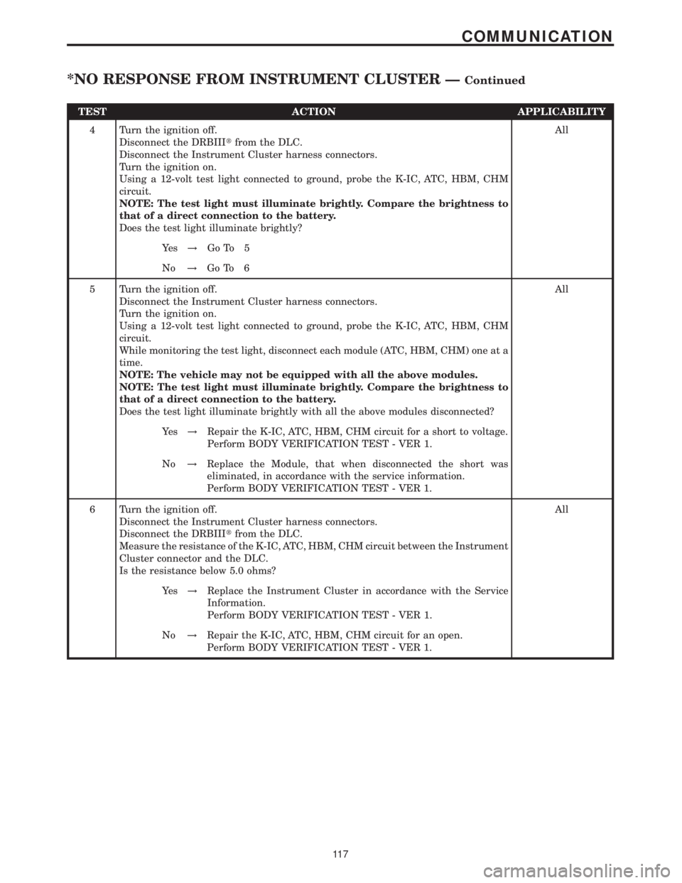
TEST ACTION APPLICABILITY
4 Turn the ignition off.
Disconnect the DRBIIItfrom the DLC.
Disconnect the Instrument Cluster harness connectors.
Turn the ignition on.
Using a 12-volt test light connected to ground, probe the K-IC, ATC, HBM, CHM
circuit.
NOTE: The test light must illuminate brightly. Compare the brightness to
that of a direct connection to the battery.
Does the test light illuminate brightly?All
Ye s!Go To 5
No!Go To 6
5 Turn the ignition off.
Disconnect the Instrument Cluster harness connectors.
Turn the ignition on.
Using a 12-volt test light connected to ground, probe the K-IC, ATC, HBM, CHM
circuit.
While monitoring the test light, disconnect each module (ATC, HBM, CHM) one at a
time.
NOTE: The vehicle may not be equipped with all the above modules.
NOTE: The test light must illuminate brightly. Compare the brightness to
that of a direct connection to the battery.
Does the test light illuminate brightly with all the above modules disconnected?All
Ye s!Repair the K-IC, ATC, HBM, CHM circuit for a short to voltage.
Perform BODY VERIFICATION TEST - VER 1.
No!Replace the Module, that when disconnected the short was
eliminated, in accordance with the service information.
Perform BODY VERIFICATION TEST - VER 1.
6 Turn the ignition off.
Disconnect the Instrument Cluster harness connectors.
Disconnect the DRBIIItfrom the DLC.
Measure the resistance of the K-IC, ATC, HBM, CHM circuit between the Instrument
Cluster connector and the DLC.
Is the resistance below 5.0 ohms?All
Ye s!Replace the Instrument Cluster in accordance with the Service
Information.
Perform BODY VERIFICATION TEST - VER 1.
No!Repair the K-IC, ATC, HBM, CHM circuit for an open.
Perform BODY VERIFICATION TEST - VER 1.
11 7
COMMUNICATION
*NO RESPONSE FROM INSTRUMENT CLUSTER ÐContinued