MERCEDES-BENZ SPRINTER 2006 Service Manual
Manufacturer: MERCEDES-BENZ, Model Year: 2006, Model line: SPRINTER, Model: MERCEDES-BENZ SPRINTER 2006Pages: 2305, PDF Size: 48.12 MB
Page 111 of 2305
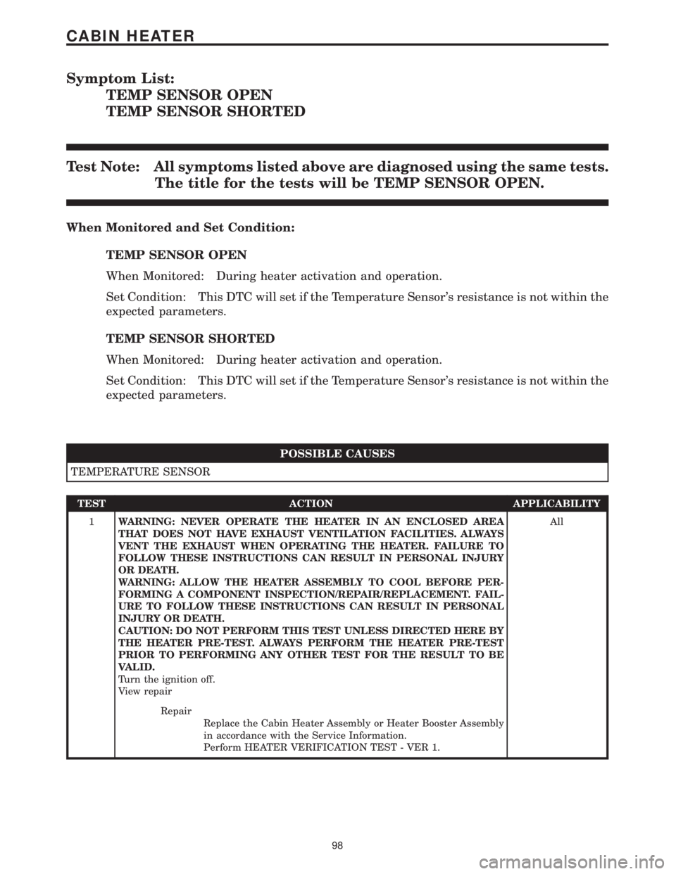
Symptom List:
TEMP SENSOR OPEN
TEMP SENSOR SHORTED
Test Note: All symptoms listed above are diagnosed using the same tests.
The title for the tests will be TEMP SENSOR OPEN.
When Monitored and Set Condition:
TEMP SENSOR OPEN
When Monitored: During heater activation and operation.
Set Condition: This DTC will set if the Temperature Sensor's resistance is not within the
expected parameters.
TEMP SENSOR SHORTED
When Monitored: During heater activation and operation.
Set Condition: This DTC will set if the Temperature Sensor's resistance is not within the
expected parameters.
POSSIBLE CAUSES
TEMPERATURE SENSOR
TEST ACTION APPLICABILITY
1WARNING: NEVER OPERATE THE HEATER IN AN ENCLOSED AREA
THAT DOES NOT HAVE EXHAUST VENTILATION FACILITIES. ALWAYS
VENT THE EXHAUST WHEN OPERATING THE HEATER. FAILURE TO
FOLLOW THESE INSTRUCTIONS CAN RESULT IN PERSONAL INJURY
OR DEATH.
WARNING: ALLOW THE HEATER ASSEMBLY TO COOL BEFORE PER-
FORMING A COMPONENT INSPECTION/REPAIR/REPLACEMENT. FAIL-
URE TO FOLLOW THESE INSTRUCTIONS CAN RESULT IN PERSONAL
INJURY OR DEATH.
CAUTION: DO NOT PERFORM THIS TEST UNLESS DIRECTED HERE BY
THE HEATER PRE-TEST. ALWAYS PERFORM THE HEATER PRE-TEST
PRIOR TO PERFORMING ANY OTHER TEST FOR THE RESULT TO BE
VALID.
Turn the ignition off.
View repairAll
Repair
Replace the Cabin Heater Assembly or Heater Booster Assembly
in accordance with the Service Information.
Perform HEATER VERIFICATION TEST - VER 1.
98
CABIN HEATER
Page 112 of 2305
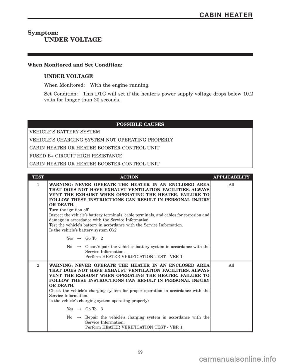
Symptom:
UNDER VOLTAGE
When Monitored and Set Condition:
UNDER VOLTAGE
When Monitored: With the engine running.
Set Condition: This DTC will set if the heater's power supply voltage drops below 10.2
volts for longer than 20 seconds.
POSSIBLE CAUSES
VEHICLE'S BATTERY SYSTEM
VEHICLE'S CHARGING SYSTEM NOT OPERATING PROPERLY
CABIN HEATER OR HEATER BOOSTER CONTROL UNIT
FUSED B+ CIRCUIT HIGH RESISTANCE
CABIN HEATER OR HEATER BOOSTER CONTROL UNIT
TEST ACTION APPLICABILITY
1WARNING: NEVER OPERATE THE HEATER IN AN ENCLOSED AREA
THAT DOES NOT HAVE EXHAUST VENTILATION FACILITIES. ALWAYS
VENT THE EXHAUST WHEN OPERATING THE HEATER. FAILURE TO
FOLLOW THESE INSTRUCTIONS CAN RESULT IN PERSONAL INJURY
OR DEATH.
Turn the ignition off.
Inspect the vehicle's battery terminals, cable terminals, and cables for corrosion and
damage in accordance with the Service Information.
Test the vehicle's battery in accordance with the Service Information.
Is the vehicle's battery system Ok?All
Ye s!Go To 2
No!Clean/repair the vehicle's battery system in accordance with the
Service Information.
Perform HEATER VERIFICATION TEST - VER 1.
2WARNING: NEVER OPERATE THE HEATER IN AN ENCLOSED AREA
THAT DOES NOT HAVE EXHAUST VENTILATION FACILITIES. ALWAYS
VENT THE EXHAUST WHEN OPERATING THE HEATER. FAILURE TO
FOLLOW THESE INSTRUCTIONS CAN RESULT IN PERSONAL INJURY
OR DEATH.
Check the vehicle's charging system for proper operation in accordance with the
Service Information.
Is the vehicle's charging system operating properly?All
Ye s!Go To 3
No!Repair the vehicle's charging system in accordance with the
Service Information.
Perform HEATER VERIFICATION TEST - VER 1.
99
CABIN HEATER
Page 113 of 2305
TEST ACTION APPLICABILITY
3WARNING: NEVER OPERATE THE HEATER IN AN ENCLOSED AREA
THAT DOES NOT HAVE EXHAUST VENTILATION FACILITIES. ALWAYS
VENT THE EXHAUST WHEN OPERATING THE HEATER. FAILURE TO
FOLLOW THESE INSTRUCTIONS CAN RESULT IN PERSONAL INJURY
OR DEATH.
WARNING: ALLOW THE HEATER ASSEMBLY TO COOL BEFORE PER-
FORMING A COMPONENT INSPECTION/REPAIR/REPLACEMENT. FAIL-
URE TO FOLLOW THESE INSTRUCTIONS CAN RESULT IN PERSONAL
INJURY OR DEATH.
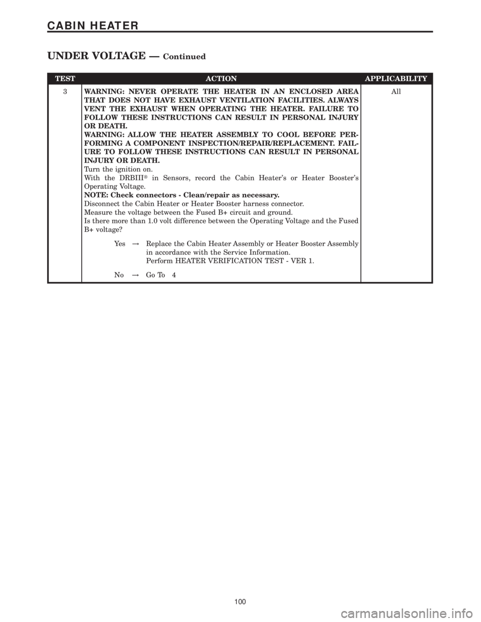
Turn the ignition on.
With the DRBIIItin Sensors, record the Cabin Heater's or Heater Booster's
Operating Voltage.
NOTE: Check connectors - Clean/repair as necessary.
Disconnect the Cabin Heater or Heater Booster harness connector.
Measure the voltage between the Fused B+ circuit and ground.
Is there more than 1.0 volt difference between the Operating Voltage and the Fused
B+ voltage?All
Ye s!Replace the Cabin Heater Assembly or Heater Booster Assembly
in accordance with the Service Information.
Perform HEATER VERIFICATION TEST - VER 1.
No!Go To 4
100
CABIN HEATER
UNDER VOLTAGE ÐContinued
Page 114 of 2305
TEST ACTION APPLICABILITY
4WARNING: NEVER OPERATE THE HEATER IN AN ENCLOSED AREA
THAT DOES NOT HAVE EXHAUST VENTILATION FACILITIES. ALWAYS
VENT THE EXHAUST WHEN OPERATING THE HEATER. FAILURE TO
FOLLOW THESE INSTRUCTIONS CAN RESULT IN PERSONAL INJURY
OR DEATH.
WARNING: ALLOW THE HEATER ASSEMBLY TO COOL BEFORE PER-
FORMING A COMPONENT INSPECTION/REPAIR/REPLACEMENT. FAIL-
URE TO FOLLOW THESE INSTRUCTIONS CAN RESULT IN PERSONAL
INJURY OR DEATH.
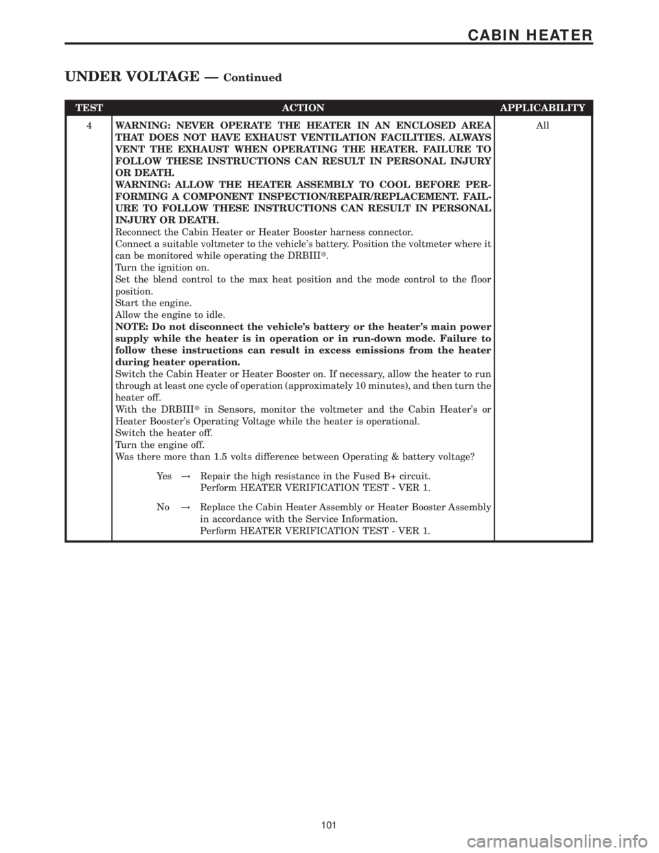
Reconnect the Cabin Heater or Heater Booster harness connector.
Connect a suitable voltmeter to the vehicle's battery. Position the voltmeter where it
can be monitored while operating the DRBIIIt.
Turn the ignition on.
Set the blend control to the max heat position and the mode control to the floor
position.
Start the engine.
Allow the engine to idle.
NOTE: Do not disconnect the vehicle's battery or the heater's main power
supply while the heater is in operation or in run-down mode. Failure to
follow these instructions can result in excess emissions from the heater
during heater operation.
Switch the Cabin Heater or Heater Booster on. If necessary, allow the heater to run
through at least one cycle of operation (approximately 10 minutes), and then turn the
heater off.
With the DRBIIItin Sensors, monitor the voltmeter and the Cabin Heater's or
Heater Booster's Operating Voltage while the heater is operational.
Switch the heater off.
Turn the engine off.
Was there more than 1.5 volts difference between Operating & battery voltage?All
Ye s!Repair the high resistance in the Fused B+ circuit.
Perform HEATER VERIFICATION TEST - VER 1.
No!Replace the Cabin Heater Assembly or Heater Booster Assembly
in accordance with the Service Information.
Perform HEATER VERIFICATION TEST - VER 1.
101
CABIN HEATER
UNDER VOLTAGE ÐContinued
Page 115 of 2305
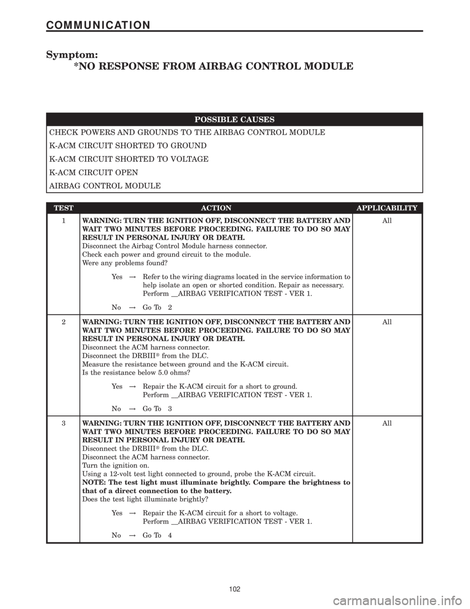
Symptom:
*NO RESPONSE FROM AIRBAG CONTROL MODULE
POSSIBLE CAUSES
CHECK POWERS AND GROUNDS TO THE AIRBAG CONTROL MODULE
K-ACM CIRCUIT SHORTED TO GROUND
K-ACM CIRCUIT SHORTED TO VOLTAGE
K-ACM CIRCUIT OPEN
AIRBAG CONTROL MODULE
TEST ACTION APPLICABILITY
1WARNING: TURN THE IGNITION OFF, DISCONNECT THE BATTERY AND
WAIT TWO MINUTES BEFORE PROCEEDING. FAILURE TO DO SO MAY
RESULT IN PERSONAL INJURY OR DEATH.
Disconnect the Airbag Control Module harness connector.
Check each power and ground circuit to the module.
Were any problems found?All
Ye s!Refer to the wiring diagrams located in the service information to
help isolate an open or shorted condition. Repair as necessary.
Perform __AIRBAG VERIFICATION TEST - VER 1.
No!Go To 2
2WARNING: TURN THE IGNITION OFF, DISCONNECT THE BATTERY AND
WAIT TWO MINUTES BEFORE PROCEEDING. FAILURE TO DO SO MAY
RESULT IN PERSONAL INJURY OR DEATH.
Disconnect the ACM harness connector.
Disconnect the DRBIIItfrom the DLC.
Measure the resistance between ground and the K-ACM circuit.
Is the resistance below 5.0 ohms?All
Ye s!Repair the K-ACM circuit for a short to ground.
Perform __AIRBAG VERIFICATION TEST - VER 1.
No!Go To 3
3WARNING: TURN THE IGNITION OFF, DISCONNECT THE BATTERY AND
WAIT TWO MINUTES BEFORE PROCEEDING. FAILURE TO DO SO MAY
RESULT IN PERSONAL INJURY OR DEATH.
Disconnect the DRBIIItfrom the DLC.
Disconnect the ACM harness connector.
Turn the ignition on.
Using a 12-volt test light connected to ground, probe the K-ACM circuit.
NOTE: The test light must illuminate brightly. Compare the brightness to
that of a direct connection to the battery.
Does the test light illuminate brightly?All
Ye s!Repair the K-ACM circuit for a short to voltage.
Perform __AIRBAG VERIFICATION TEST - VER 1.
No!Go To 4
102
COMMUNICATION
Page 116 of 2305
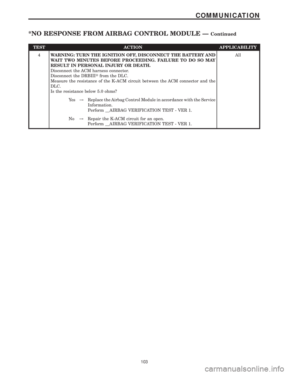
TEST ACTION APPLICABILITY
4WARNING: TURN THE IGNITION OFF, DISCONNECT THE BATTERY AND
WAIT TWO MINUTES BEFORE PROCEEDING. FAILURE TO DO SO MAY
RESULT IN PERSONAL INJURY OR DEATH.
Disconnect the ACM harness connector.
Disconnect the DRBIIItfrom the DLC.
Measure the resistance of the K-ACM circuit between the ACM connector and the
DLC.
Is the resistance below 5.0 ohms?All
Ye s!Replace the Airbag Control Module in accordance with the Service
Information.
Perform __AIRBAG VERIFICATION TEST - VER 1.
No!Repair the K-ACM circuit for an open.
Perform __AIRBAG VERIFICATION TEST - VER 1.
103
COMMUNICATION
*NO RESPONSE FROM AIRBAG CONTROL MODULE ÐContinued
Page 117 of 2305
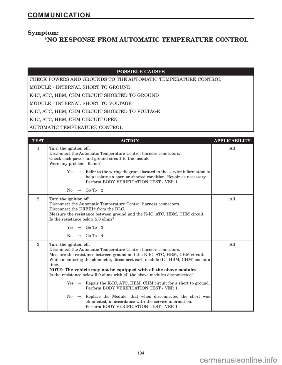
Symptom:
*NO RESPONSE FROM AUTOMATIC TEMPERATURE CONTROL
POSSIBLE CAUSES
CHECK POWERS AND GROUNDS TO THE AUTOMATIC TEMPERATURE CONTROL
MODULE - INTERNAL SHORT TO GROUND
K-IC, ATC, HBM, CHM CIRCUIT SHORTED TO GROUND
MODULE - INTERNAL SHORT TO VOLTAGE
K-IC, ATC, HBM, CHM CIRCUIT SHORTED TO VOLTAGE
K-IC, ATC, HBM, CHM CIRCUIT OPEN
AUTOMATIC TEMPERATURE CONTROL
TEST ACTION APPLICABILITY
1 Turn the ignition off.
Disconnect the Automatic Temperature Control harness connectors.
Check each power and ground circuit to the module.
Were any problems found?All
Ye s!Refer to the wiring diagrams located in the service information to
help isolate an open or shorted condition. Repair as necessary.
Perform BODY VERIFICATION TEST - VER 1.
No!Go To 2
2 Turn the ignition off.
Disconnect the Automatic Temperature Control harness connectors.
Disconnect the DRBIIItfrom the DLC.
Measure the resistance between ground and the K-IC, ATC, HBM, CHM circuit.
Is the resistance below 5.0 ohms?All
Ye s!Go To 3
No!Go To 4
3 Turn the ignition off.
Disconnect the Automatic Temperature Control harness connectors.
Measure the resistance between ground and the K-IC, ATC, HBM, CHM circuit.
While monitoring the ohmmeter, disconnect each module (IC, HBM, CHM) one at a
time.
NOTE: The vehicle may not be equipped with all the above modules.
Is the resistance below 5.0 ohms with all the above modules disconnected?All
Ye s!Repair the K-IC, ATC, HBM, CHM circuit for a short to ground.
Perform BODY VERIFICATION TEST - VER 1.
No!Replace the Module, that when disconnected the short was
eliminated, in accordance with the service information.
Perform BODY VERIFICATION TEST - VER 1.
104
COMMUNICATION
Page 118 of 2305
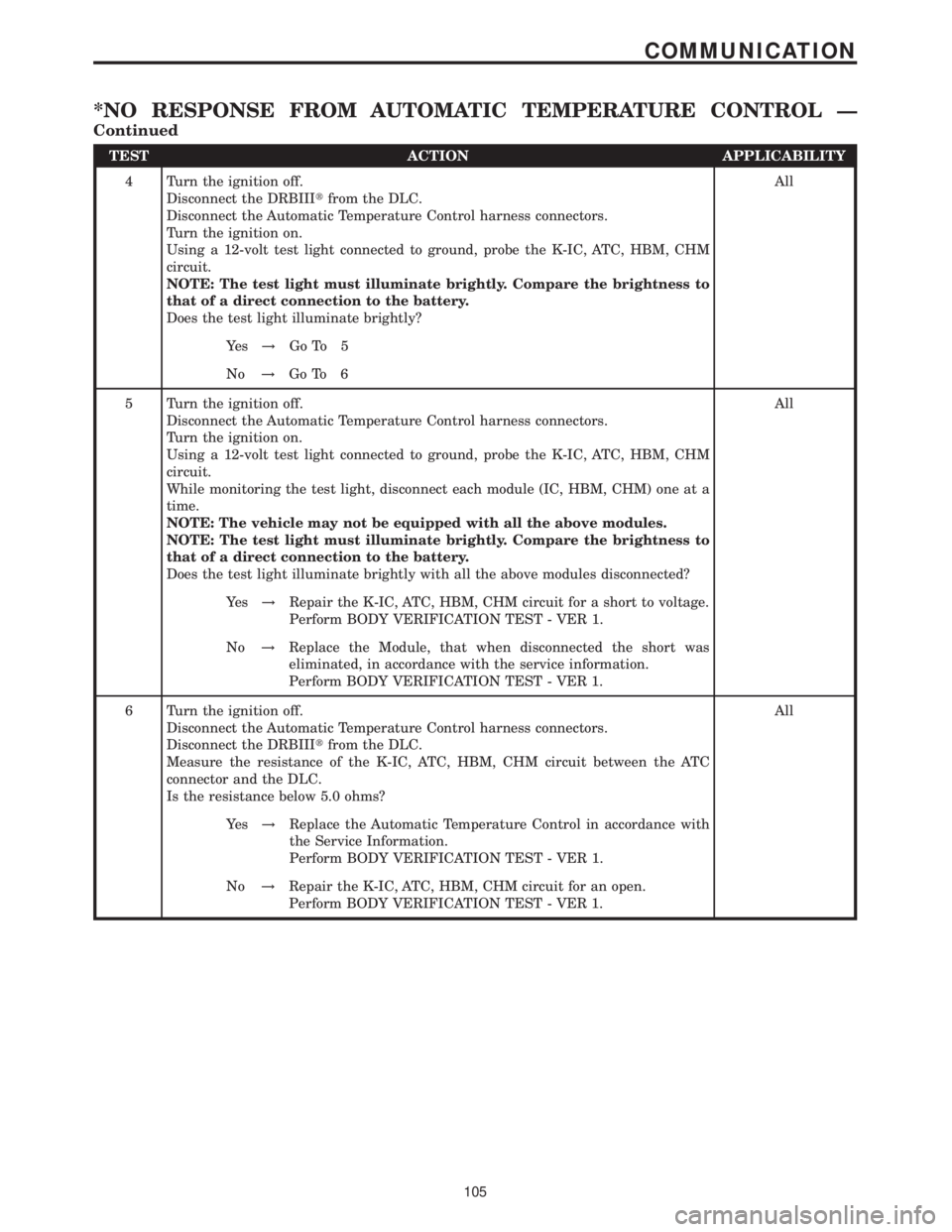
TEST ACTION APPLICABILITY
4 Turn the ignition off.
Disconnect the DRBIIItfrom the DLC.
Disconnect the Automatic Temperature Control harness connectors.
Turn the ignition on.
Using a 12-volt test light connected to ground, probe the K-IC, ATC, HBM, CHM
circuit.
NOTE: The test light must illuminate brightly. Compare the brightness to
that of a direct connection to the battery.
Does the test light illuminate brightly?All
Ye s!Go To 5
No!Go To 6
5 Turn the ignition off.
Disconnect the Automatic Temperature Control harness connectors.
Turn the ignition on.
Using a 12-volt test light connected to ground, probe the K-IC, ATC, HBM, CHM
circuit.
While monitoring the test light, disconnect each module (IC, HBM, CHM) one at a
time.
NOTE: The vehicle may not be equipped with all the above modules.
NOTE: The test light must illuminate brightly. Compare the brightness to
that of a direct connection to the battery.
Does the test light illuminate brightly with all the above modules disconnected?All
Ye s!Repair the K-IC, ATC, HBM, CHM circuit for a short to voltage.
Perform BODY VERIFICATION TEST - VER 1.
No!Replace the Module, that when disconnected the short was
eliminated, in accordance with the service information.
Perform BODY VERIFICATION TEST - VER 1.
6 Turn the ignition off.
Disconnect the Automatic Temperature Control harness connectors.
Disconnect the DRBIIItfrom the DLC.
Measure the resistance of the K-IC, ATC, HBM, CHM circuit between the ATC
connector and the DLC.
Is the resistance below 5.0 ohms?All
Ye s!Replace the Automatic Temperature Control in accordance with
the Service Information.
Perform BODY VERIFICATION TEST - VER 1.
No!Repair the K-IC, ATC, HBM, CHM circuit for an open.
Perform BODY VERIFICATION TEST - VER 1.
105
COMMUNICATION
*NO RESPONSE FROM AUTOMATIC TEMPERATURE CONTROL Ð
Continued
Page 119 of 2305
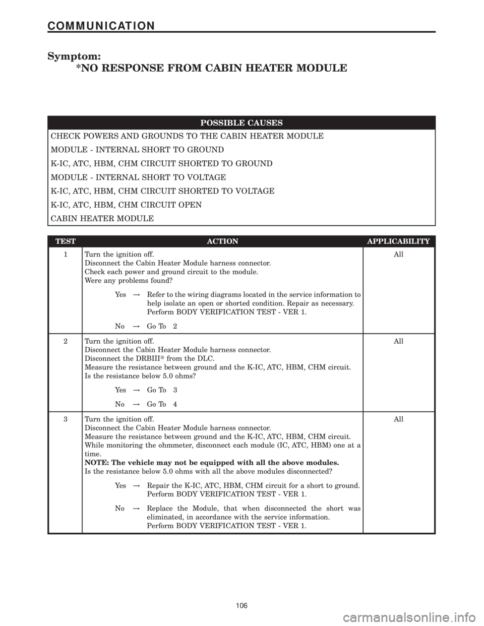
Symptom:
*NO RESPONSE FROM CABIN HEATER MODULE
POSSIBLE CAUSES
CHECK POWERS AND GROUNDS TO THE CABIN HEATER MODULE
MODULE - INTERNAL SHORT TO GROUND
K-IC, ATC, HBM, CHM CIRCUIT SHORTED TO GROUND
MODULE - INTERNAL SHORT TO VOLTAGE
K-IC, ATC, HBM, CHM CIRCUIT SHORTED TO VOLTAGE
K-IC, ATC, HBM, CHM CIRCUIT OPEN
CABIN HEATER MODULE
TEST ACTION APPLICABILITY
1 Turn the ignition off.
Disconnect the Cabin Heater Module harness connector.
Check each power and ground circuit to the module.
Were any problems found?All
Ye s!Refer to the wiring diagrams located in the service information to
help isolate an open or shorted condition. Repair as necessary.
Perform BODY VERIFICATION TEST - VER 1.
No!Go To 2
2 Turn the ignition off.
Disconnect the Cabin Heater Module harness connector.
Disconnect the DRBIIItfrom the DLC.
Measure the resistance between ground and the K-IC, ATC, HBM, CHM circuit.
Is the resistance below 5.0 ohms?All
Ye s!Go To 3
No!Go To 4
3 Turn the ignition off.
Disconnect the Cabin Heater Module harness connector.
Measure the resistance between ground and the K-IC, ATC, HBM, CHM circuit.
While monitoring the ohmmeter, disconnect each module (IC, ATC, HBM) one at a
time.
NOTE: The vehicle may not be equipped with all the above modules.
Is the resistance below 5.0 ohms with all the above modules disconnected?All
Ye s!Repair the K-IC, ATC, HBM, CHM circuit for a short to ground.
Perform BODY VERIFICATION TEST - VER 1.
No!Replace the Module, that when disconnected the short was
eliminated, in accordance with the service information.
Perform BODY VERIFICATION TEST - VER 1.
106
COMMUNICATION
Page 120 of 2305
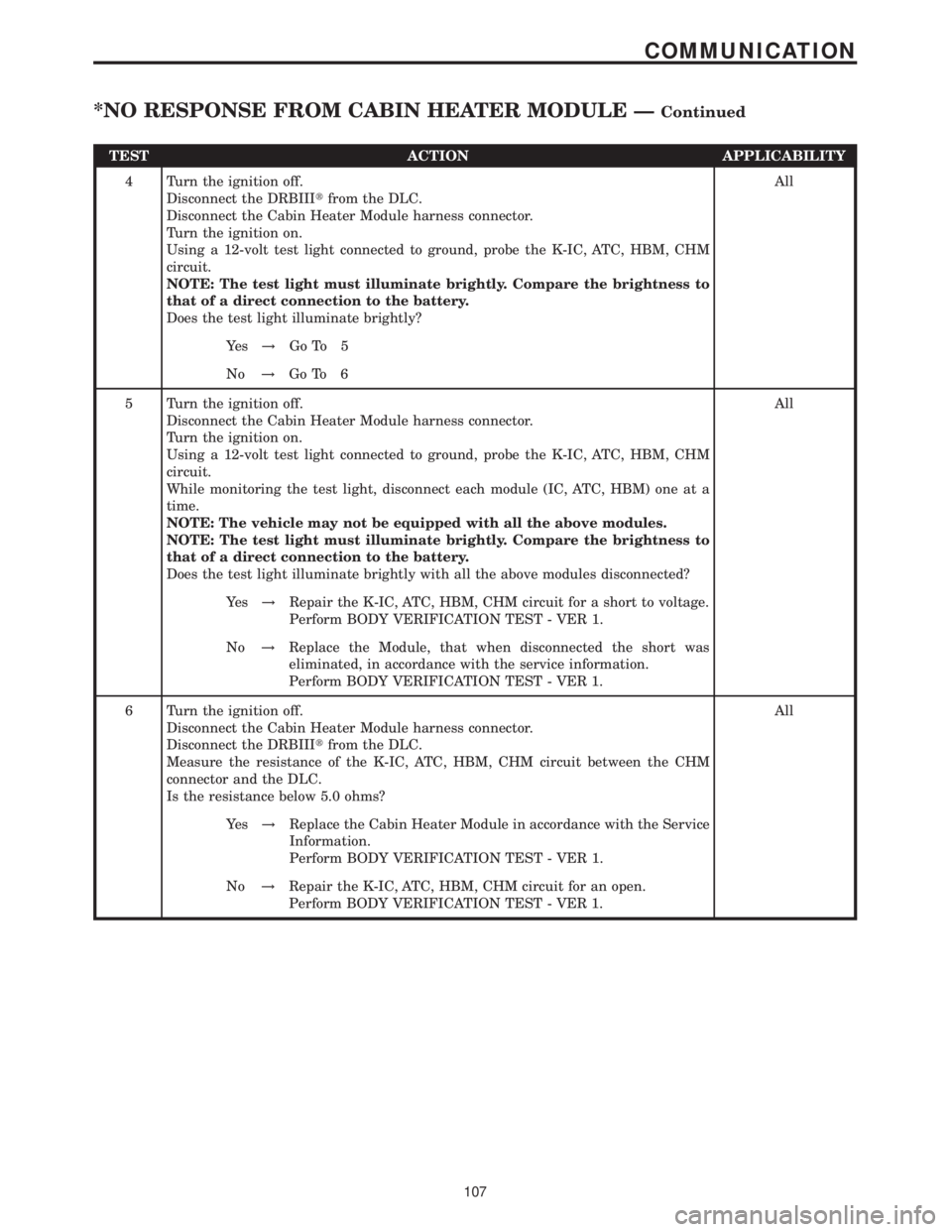
TEST ACTION APPLICABILITY
4 Turn the ignition off.
Disconnect the DRBIIItfrom the DLC.
Disconnect the Cabin Heater Module harness connector.
Turn the ignition on.
Using a 12-volt test light connected to ground, probe the K-IC, ATC, HBM, CHM
circuit.
NOTE: The test light must illuminate brightly. Compare the brightness to
that of a direct connection to the battery.
Does the test light illuminate brightly?All
Ye s!Go To 5
No!Go To 6
5 Turn the ignition off.
Disconnect the Cabin Heater Module harness connector.
Turn the ignition on.
Using a 12-volt test light connected to ground, probe the K-IC, ATC, HBM, CHM
circuit.
While monitoring the test light, disconnect each module (IC, ATC, HBM) one at a
time.
NOTE: The vehicle may not be equipped with all the above modules.
NOTE: The test light must illuminate brightly. Compare the brightness to
that of a direct connection to the battery.
Does the test light illuminate brightly with all the above modules disconnected?All
Ye s!Repair the K-IC, ATC, HBM, CHM circuit for a short to voltage.
Perform BODY VERIFICATION TEST - VER 1.
No!Replace the Module, that when disconnected the short was
eliminated, in accordance with the service information.
Perform BODY VERIFICATION TEST - VER 1.
6 Turn the ignition off.
Disconnect the Cabin Heater Module harness connector.
Disconnect the DRBIIItfrom the DLC.
Measure the resistance of the K-IC, ATC, HBM, CHM circuit between the CHM
connector and the DLC.
Is the resistance below 5.0 ohms?All
Ye s!Replace the Cabin Heater Module in accordance with the Service
Information.
Perform BODY VERIFICATION TEST - VER 1.
No!Repair the K-IC, ATC, HBM, CHM circuit for an open.
Perform BODY VERIFICATION TEST - VER 1.
107
COMMUNICATION
*NO RESPONSE FROM CABIN HEATER MODULE ÐContinued