MERCEDES-BENZ SPRINTER 2006 Service Manual
Manufacturer: MERCEDES-BENZ, Model Year: 2006, Model line: SPRINTER, Model: MERCEDES-BENZ SPRINTER 2006Pages: 2305, PDF Size: 48.12 MB
Page 821 of 2305
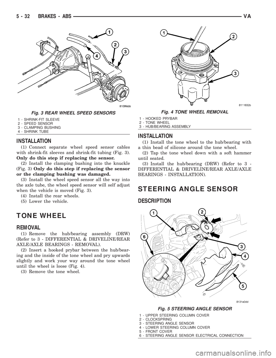
INSTALLATION
(1) Connect separate wheel speed sensor cables
with shrink-fit sleeves and shrink-fit tubing (Fig. 3).
Only do this step if replacing the sensor.
(2) Install the clamping bushing into the knuckle
(Fig. 3)Only do this step if replacing the sensor
or the clamping bushing was damaged.
(3) Install the wheel speed sensor all the way into
the axle tube, the wheel speed sensor will self adjust
when the vehicle is moved (Fig. 3).
(4) Install the rear wheels.
(5) Lower the vehicle.
TONE WHEEL
REMOVAL
(1) Remove the hub/bearing assembly (DRW)
(Refer to 3 - DIFFERENTIAL & DRIVELINE/REAR
AXLE/AXLE BEARINGS - REMOVAL).
(2) Insert a hooked prybar between the hub/bear-
ing and the inside of the tone wheel and pry upwards
slightly and work your way around the tone wheel
until the wheel is loose (Fig. 4).
(3) Remove the tone wheel.
INSTALLATION
(1) Install the tone wheel to the hub/bearing with
a thin bead of silicone around the tone wheel.
(2) Tap the tone wheel down with a soft hammer
until seated.
(3) Install the hub/bearing (DRW) (Refer to 3 -
DIFFERENTIAL & DRIVELINE/REAR AXLE/AXLE
BEARINGS - INSTALLATION).
STEERING ANGLE SENSOR
DESCRIPTION
Fig. 3 REAR WHEEL SPEED SENSORS
1 - SHRINK-FIT SLEEVE
2 - SPEED SENSOR
3 - CLAMPING BUSHING
4 - SHRINK TUBE
Fig. 4 TONE WHEEL REMOVAL
1 - HOOKED PRYBAR
2 - TONE WHEEL
3 - HUB/BEARING ASSEMBLY
Fig. 5 STEERING ANGLE SENSOR
1 - UPPER STEERING COLUMN COVER
2 - CLOCKSPRING
3 - STEERING ANGLE SENSOR
4 - LOWER STEERING COLUMN COVER
5 - FRONT COVER
6 - STEERING ANGLE SENSOR ELECTRICAL CONNECTION
5 - 32 BRAKES - ABSVA
Page 822 of 2305
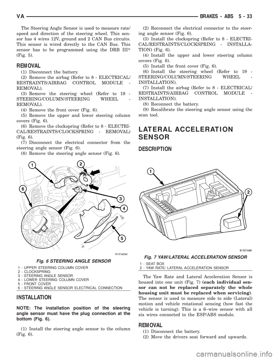
The Steering Angle Sensor is used to measure rate/
speed and direction of the steering wheel. This sen-
sor has 4 wires 12V, ground and 2 CAN Bus circuits.
This sensor is wired directly to the CAN Bus. This
sensor has to be programmed using the DRB IIIt
(Fig. 5).
REMOVAL
(1) Disconnect the battery.
(2) Remove the airbag (Refer to 8 - ELECTRICAL/
RESTRAINTS/AIRBAG CONTROL MODULE -
REMOVAL).
(3) Remove the steering wheel (Refer to 19 -
STEERING/COLUMN/STEERING WHEEL -
REMOVAL).
(4) Remove the front cover (Fig. 6).
(5) Remove the upper and lower steering column
covers (Fig. 6).
(6) Remove the clockspring (Refer to 8 - ELECTRI-
CAL/RESTRAINTS/CLOCKSPRING - REMOVAL)
(Fig. 6).
(7) Disconnect the electrical connector from the
steering angle sensor (Fig. 6).
(8) Remove the steering angle sensor (Fig. 6).
INSTALLATION
NOTE: The installation position of the steering
angle sensor must have the plug connection at the
bottom (Fig. 6).
(1) Install the steering angle sensor to the column
(Fig. 6).(2) Reconnect the electrical connector to the steer-
ing angle sensor (Fig. 6).
(3) Install the clockspring (Refer to 8 - ELECTRI-
CAL/RESTRAINTS/CLOCKSPRING - INSTALLA-
TION) (Fig. 6).
(4) Install the upper and lower steering column
covers (Fig. 6).
(5) Install the front cover (Fig. 6).
(6) Install the steering wheel (Refer to 19 -
STEERING/COLUMN/STEERING WHEEL -
INSTALLATION).
(7) Install the airbag (Refer to 8 - ELECTRICAL/
RESTRAINTS/AIRBAG CONTROL MODULE -
INSTALLATION).
(8) Reconnect the battery.
(9) Recalibrate the steering angle sensor using the
scan tool.
LATERAL ACCELERATION
SENSOR
DESCRIPTION
The Yaw Rate and Lateral Acceleration Sensor is
housed into one unit (Fig. 7)(each individual sen-
sor can not be replaced separately the whole
housing unit must be replaced when servicing).
The sensor is used to measure side to side (Lateral)
motion and vehicle rotational sensing (how fast the
vehicle is turning). This is a 6±wire sensor with all
six wires connected to the ESP/ABS module.
REMOVAL
(1) Disconnect the battery.
(2) Move the drivers seat forward and upwards.
Fig. 6 STEERING ANGLE SENSOR
1 - UPPER STEERING COLUMN COVER
2 - CLOCKSPRING
3 - STEERING ANGLE SENSOR
4 - LOWER STEERING COLUMN COVER
5 - FRONT COVER
6 - STEERING ANGLE SENSOR ELECTRICAL CONNECTION
Fig. 7 YAW/LATERAL ACCELERATION SENSOR
1 - SEAT BOX
2 - YAW RATE/ LATERAL ACCELERATION SENSOR
VABRAKES - ABS 5 - 33
Page 823 of 2305
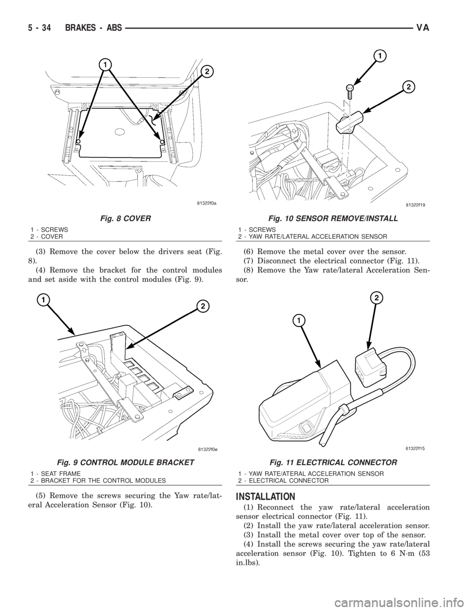
(3) Remove the cover below the drivers seat (Fig.
8).
(4) Remove the bracket for the control modules
and set aside with the control modules (Fig. 9).
(5) Remove the screws securing the Yaw rate/lat-
eral Acceleration Sensor (Fig. 10).(6) Remove the metal cover over the sensor.
(7) Disconnect the electrical connector (Fig. 11).
(8) Remove the Yaw rate/lateral Acceleration Sen-
sor.
INSTALLATION
(1) Reconnect the yaw rate/lateral acceleration
sensor electrical connector (Fig. 11).
(2) Install the yaw rate/lateral acceleration sensor.
(3) Install the metal cover over top of the sensor.
(4) Install the screws securing the yaw rate/lateral
acceleration sensor (Fig. 10). Tighten to 6 N´m (53
in.lbs).
Fig. 8 COVER
1 - SCREWS
2 - COVER
Fig. 9 CONTROL MODULE BRACKET
1 - SEAT FRAME
2 - BRACKET FOR THE CONTROL MODULES
Fig. 10 SENSOR REMOVE/INSTALL
1 - SCREWS
2 - YAW RATE/LATERAL ACCELERATION SENSOR
Fig. 11 ELECTRICAL CONNECTOR
1 - YAW RATE/ATERAL ACCELERATION SENSOR
2 - ELECTRICAL CONNECTOR
5 - 34 BRAKES - ABSVA
Page 824 of 2305
(5) Install the bracket with the control modules
(Fig. 9).
(6) Install the cover for the drivers seat (Fig. 8).
(7) Return the drivers seat to normal position.
(8) Reconnect the battery.
(9) Perform diagnosis quick check and road test
the vehicle.
YAW RATE SENSOR
DESCRIPTION
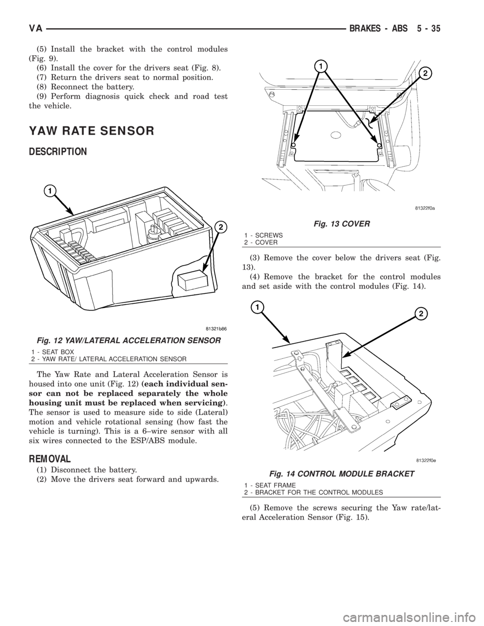
The Yaw Rate and Lateral Acceleration Sensor is
housed into one unit (Fig. 12)(each individual sen-
sor can not be replaced separately the whole
housing unit must be replaced when servicing).
The sensor is used to measure side to side (Lateral)
motion and vehicle rotational sensing (how fast the
vehicle is turning). This is a 6±wire sensor with all
six wires connected to the ESP/ABS module.
REMOVAL
(1) Disconnect the battery.
(2) Move the drivers seat forward and upwards.(3) Remove the cover below the drivers seat (Fig.
13).
(4) Remove the bracket for the control modules
and set aside with the control modules (Fig. 14).
(5) Remove the screws securing the Yaw rate/lat-
eral Acceleration Sensor (Fig. 15).
Fig. 12 YAW/LATERAL ACCELERATION SENSOR
1 - SEAT BOX
2 - YAW RATE/ LATERAL ACCELERATION SENSOR
Fig. 13 COVER
1 - SCREWS
2 - COVER
Fig. 14 CONTROL MODULE BRACKET
1 - SEAT FRAME
2 - BRACKET FOR THE CONTROL MODULES
VABRAKES - ABS 5 - 35
Page 825 of 2305
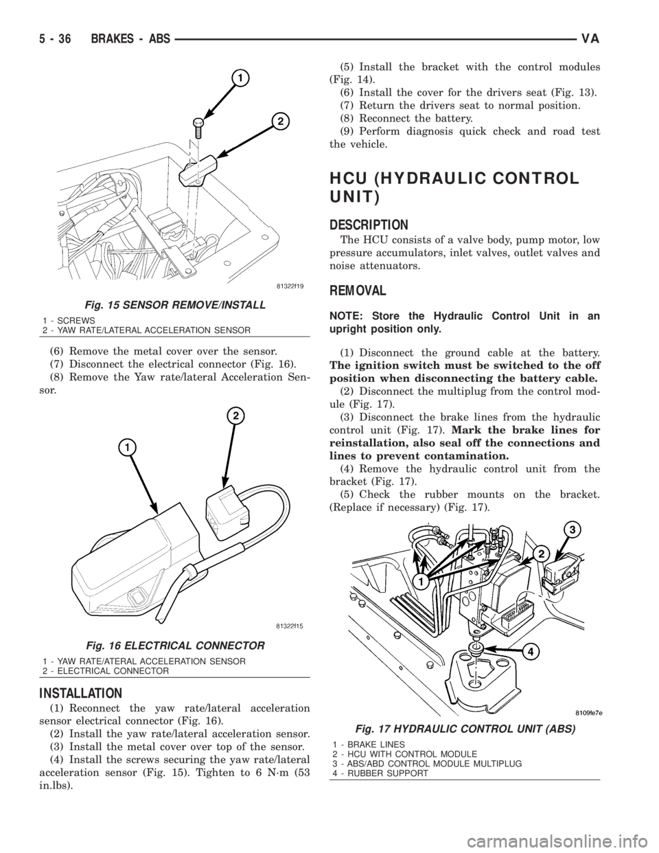
(6) Remove the metal cover over the sensor.
(7) Disconnect the electrical connector (Fig. 16).
(8) Remove the Yaw rate/lateral Acceleration Sen-
sor.
INSTALLATION
(1) Reconnect the yaw rate/lateral acceleration
sensor electrical connector (Fig. 16).
(2) Install the yaw rate/lateral acceleration sensor.
(3) Install the metal cover over top of the sensor.
(4) Install the screws securing the yaw rate/lateral
acceleration sensor (Fig. 15). Tighten to 6 N´m (53
in.lbs).(5) Install the bracket with the control modules
(Fig. 14).
(6) Install the cover for the drivers seat (Fig. 13).
(7) Return the drivers seat to normal position.
(8) Reconnect the battery.
(9) Perform diagnosis quick check and road test
the vehicle.
HCU (HYDRAULIC CONTROL
UNIT)
DESCRIPTION
The HCU consists of a valve body, pump motor, low
pressure accumulators, inlet valves, outlet valves and
noise attenuators.
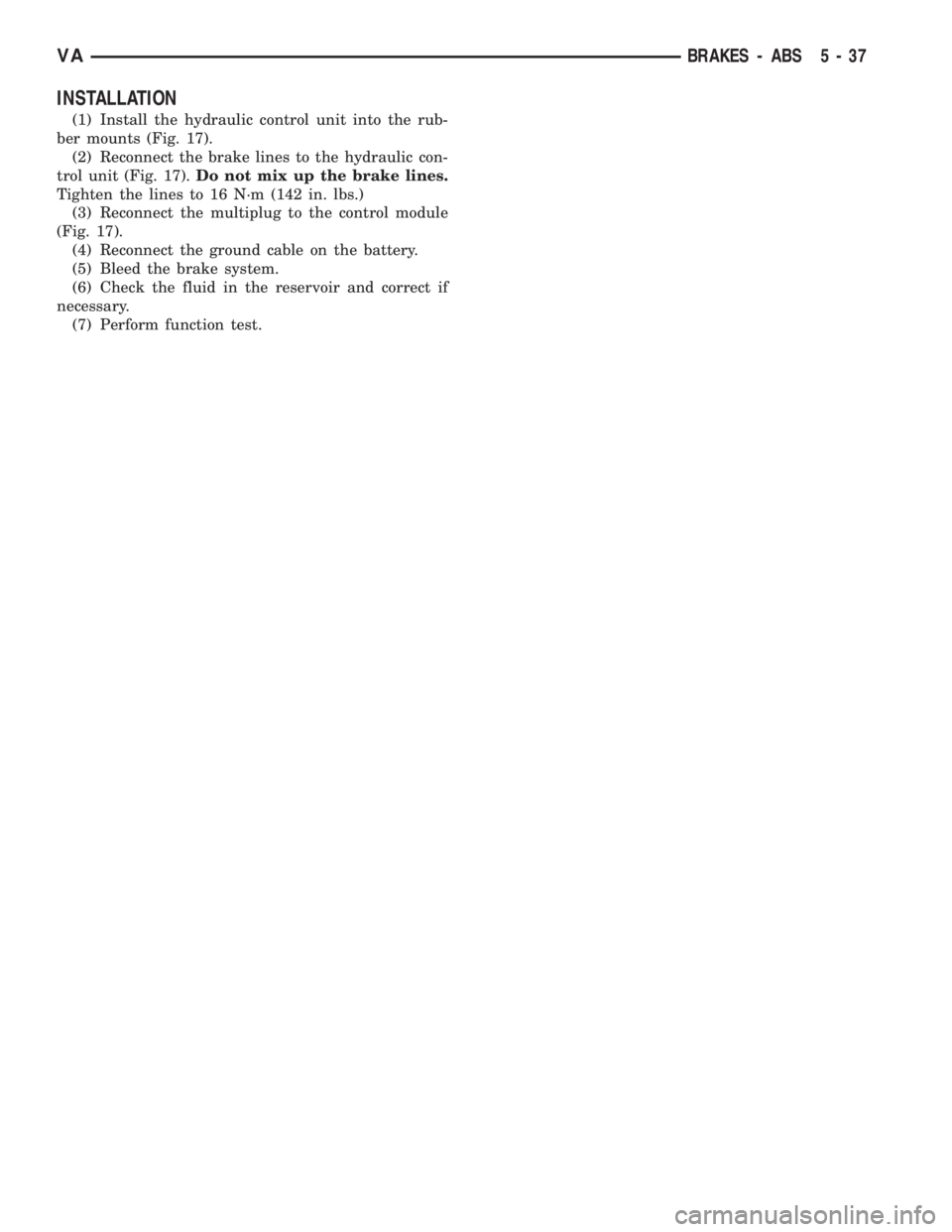
REMOVAL
NOTE: Store the Hydraulic Control Unit in an
upright position only.
(1) Disconnect the ground cable at the battery.
The ignition switch must be switched to the off
position when disconnecting the battery cable.
(2) Disconnect the multiplug from the control mod-
ule (Fig. 17).
(3) Disconnect the brake lines from the hydraulic
control unit (Fig. 17).Mark the brake lines for
reinstallation, also seal off the connections and
lines to prevent contamination.
(4) Remove the hydraulic control unit from the
bracket (Fig. 17).
(5) Check the rubber mounts on the bracket.
(Replace if necessary) (Fig. 17).
Fig. 15 SENSOR REMOVE/INSTALL
1 - SCREWS
2 - YAW RATE/LATERAL ACCELERATION SENSOR
Fig. 16 ELECTRICAL CONNECTOR
1 - YAW RATE/ATERAL ACCELERATION SENSOR
2 - ELECTRICAL CONNECTOR
Fig. 17 HYDRAULIC CONTROL UNIT (ABS)
1 - BRAKE LINES
2 - HCU WITH CONTROL MODULE
3 - ABS/ABD CONTROL MODULE MULTIPLUG
4 - RUBBER SUPPORT
5 - 36 BRAKES - ABSVA
Page 826 of 2305
INSTALLATION
(1) Install the hydraulic control unit into the rub-
ber mounts (Fig. 17).
(2) Reconnect the brake lines to the hydraulic con-
trol unit (Fig. 17).Do not mix up the brake lines.
Tighten the lines to 16 N´m (142 in. lbs.)
(3) Reconnect the multiplug to the control module
(Fig. 17).
(4) Reconnect the ground cable on the battery.
(5) Bleed the brake system.
(6) Check the fluid in the reservoir and correct if
necessary.
(7) Perform function test.
VABRAKES - ABS 5 - 37
Page 827 of 2305

Page 828 of 2305
COOLING
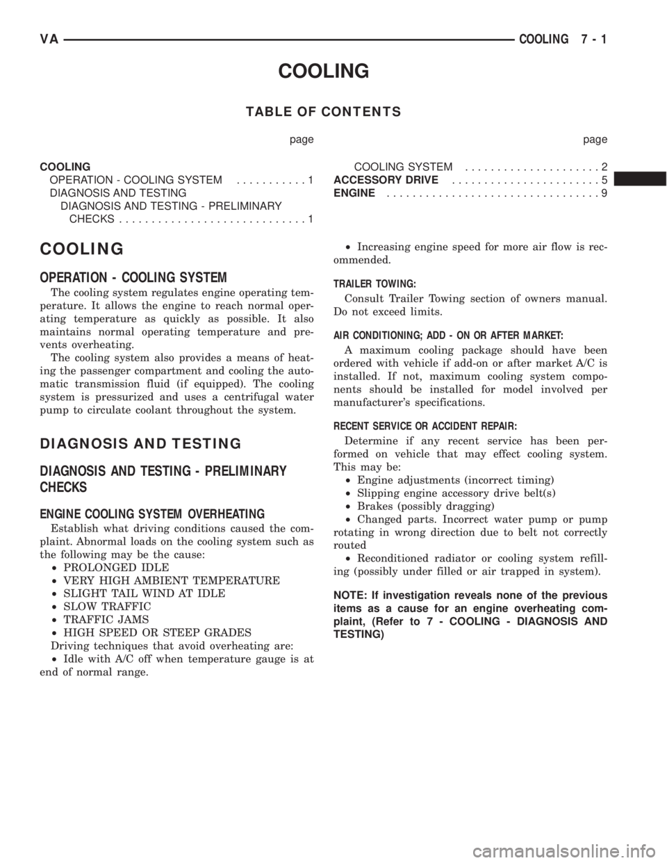
TABLE OF CONTENTS
page page
COOLING
OPERATION - COOLING SYSTEM...........1
DIAGNOSIS AND TESTING
DIAGNOSIS AND TESTING - PRELIMINARY
CHECKS.............................1COOLING SYSTEM.....................2
ACCESSORY DRIVE.......................5
ENGINE.................................9
COOLING
OPERATION - COOLING SYSTEM
The cooling system regulates engine operating tem-
perature. It allows the engine to reach normal oper-
ating temperature as quickly as possible. It also
maintains normal operating temperature and pre-
vents overheating.
The cooling system also provides a means of heat-
ing the passenger compartment and cooling the auto-
matic transmission fluid (if equipped). The cooling
system is pressurized and uses a centrifugal water
pump to circulate coolant throughout the system.
DIAGNOSIS AND TESTING
DIAGNOSIS AND TESTING - PRELIMINARY
CHECKS
ENGINE COOLING SYSTEM OVERHEATING
Establish what driving conditions caused the com-
plaint. Abnormal loads on the cooling system such as
the following may be the cause:
²PROLONGED IDLE
²VERY HIGH AMBIENT TEMPERATURE
²SLIGHT TAIL WIND AT IDLE
²SLOW TRAFFIC
²TRAFFIC JAMS
²HIGH SPEED OR STEEP GRADES
Driving techniques that avoid overheating are:
²Idle with A/C off when temperature gauge is at
end of normal range.²Increasing engine speed for more air flow is rec-
ommended.
TRAILER TOWING:
Consult Trailer Towing section of owners manual.
Do not exceed limits.
AIR CONDITIONING; ADD - ON OR AFTER MARKET:
A maximum cooling package should have been
ordered with vehicle if add-on or after market A/C is
installed. If not, maximum cooling system compo-
nents should be installed for model involved per
manufacturer's specifications.
RECENT SERVICE OR ACCIDENT REPAIR:
Determine if any recent service has been per-
formed on vehicle that may effect cooling system.
This may be:
²Engine adjustments (incorrect timing)
²Slipping engine accessory drive belt(s)
²Brakes (possibly dragging)
²Changed parts. Incorrect water pump or pump
rotating in wrong direction due to belt not correctly
routed
²Reconditioned radiator or cooling system refill-
ing (possibly under filled or air trapped in system).
NOTE: If investigation reveals none of the previous
items as a cause for an engine overheating com-
plaint, (Refer to 7 - COOLING - DIAGNOSIS AND
TESTING)
VACOOLING 7 - 1
Page 829 of 2305
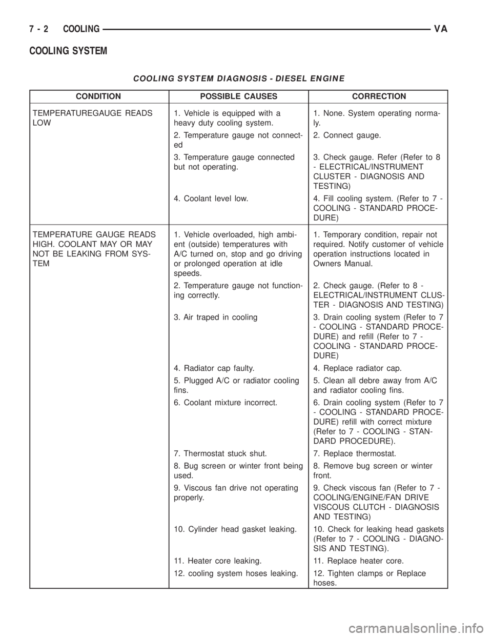
COOLING SYSTEM
COOLING SYSTEM DIAGNOSIS - DIESEL ENGINE
CONDITION POSSIBLE CAUSES CORRECTION
TEMPERATUREGAUGE READS
LOW1. Vehicle is equipped with a
heavy duty cooling system.1. None. System operating norma-
ly.
2. Temperature gauge not connect-
ed2. Connect gauge.
3. Temperature gauge connected
but not operating.3. Check gauge. Refer (Refer to 8
- ELECTRICAL/INSTRUMENT
CLUSTER - DIAGNOSIS AND
TESTING)
4. Coolant level low. 4. Fill cooling system. (Refer to 7 -
COOLING - STANDARD PROCE-
DURE)
TEMPERATURE GAUGE READS
HIGH. COOLANT MAY OR MAY
NOT BE LEAKING FROM SYS-
TEM1. Vehicle overloaded, high ambi-
ent (outside) temperatures with
A/C turned on, stop and go driving
or prolonged operation at idle
speeds.1. Temporary condition, repair not
required. Notify customer of vehicle
operation instructions located in
Owners Manual.
2. Temperature gauge not function-
ing correctly.2. Check gauge. (Refer to 8 -
ELECTRICAL/INSTRUMENT CLUS-
TER - DIAGNOSIS AND TESTING)
3. Air traped in cooling 3. Drain cooling system (Refer to 7
- COOLING - STANDARD PROCE-
DURE) and refill (Refer to 7 -
COOLING - STANDARD PROCE-
DURE)
4. Radiator cap faulty. 4. Replace radiator cap.
5. Plugged A/C or radiator cooling
fins.5. Clean all debre away from A/C
and radiator cooling fins.
6. Coolant mixture incorrect. 6. Drain cooling system (Refer to 7
- COOLING - STANDARD PROCE-
DURE) refill with correct mixture
(Refer to 7 - COOLING - STAN-
DARD PROCEDURE).
7. Thermostat stuck shut. 7. Replace thermostat.
8. Bug screen or winter front being
used.8. Remove bug screen or winter
front.
9. Viscous fan drive not operating
properly.9. Check viscous fan (Refer to 7 -
COOLING/ENGINE/FAN DRIVE
VISCOUS CLUTCH - DIAGNOSIS
AND TESTING)
10. Cylinder head gasket leaking. 10. Check for leaking head gaskets
(Refer to 7 - COOLING - DIAGNO-
SIS AND TESTING).
11. Heater core leaking. 11. Replace heater core.
12. cooling system hoses leaking. 12. Tighten clamps or Replace
hoses.
7 - 2 COOLINGVA
Page 830 of 2305
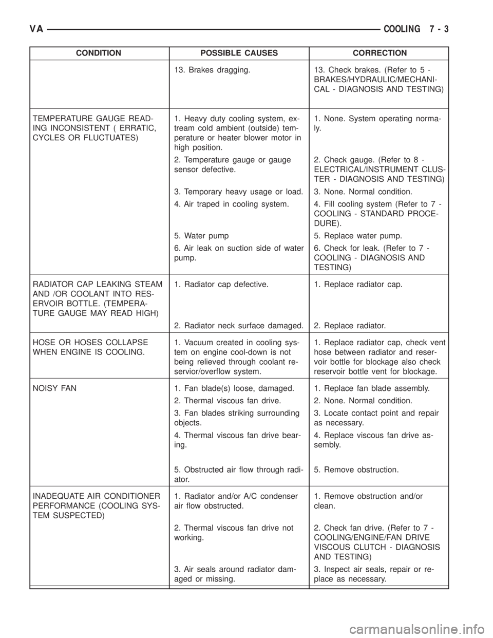
CONDITION POSSIBLE CAUSES CORRECTION
13. Brakes dragging. 13. Check brakes. (Refer to 5 -
BRAKES/HYDRAULIC/MECHANI-
CAL - DIAGNOSIS AND TESTING)
TEMPERATURE GAUGE READ-
ING INCONSISTENT ( ERRATIC,
CYCLES OR FLUCTUATES)1. Heavy duty cooling system, ex-
tream cold ambient (outside) tem-
perature or heater blower motor in
high position.1. None. System operating norma-
ly.
2. Temperature gauge or gauge
sensor defective.2. Check gauge. (Refer to 8 -
ELECTRICAL/INSTRUMENT CLUS-
TER - DIAGNOSIS AND TESTING)
3. Temporary heavy usage or load. 3. None. Normal condition.
4. Air traped in cooling system. 4. Fill cooling system (Refer to 7 -
COOLING - STANDARD PROCE-
DURE).
5. Water pump 5. Replace water pump.
6. Air leak on suction side of water
pump.6. Check for leak. (Refer to 7 -
COOLING - DIAGNOSIS AND
TESTING)
RADIATOR CAP LEAKING STEAM
AND /OR COOLANT INTO RES-
ERVOIR BOTTLE. (TEMPERA-
TURE GAUGE MAY READ HIGH)1. Radiator cap defective. 1. Replace radiator cap.
2. Radiator neck surface damaged. 2. Replace radiator.
HOSE OR HOSES COLLAPSE
WHEN ENGINE IS COOLING.1. Vacuum created in cooling sys-
tem on engine cool-down is not
being relieved through coolant re-
servior/overflow system.1. Replace radiator cap, check vent
hose between radiator and reser-
voir bottle for blockage also check
reservoir bottle vent for blockage.
NOISY FAN 1. Fan blade(s) loose, damaged. 1. Replace fan blade assembly.
2. Thermal viscous fan drive. 2. None. Normal condition.
3. Fan blades striking surrounding
objects.3. Locate contact point and repair
as necessary.
4. Thermal viscous fan drive bear-
ing.4. Replace viscous fan drive as-
sembly.
5. Obstructed air flow through radi-
ator.5. Remove obstruction.
INADEQUATE AIR CONDITIONER
PERFORMANCE (COOLING SYS-
TEM SUSPECTED)1. Radiator and/or A/C condenser
air flow obstructed.1. Remove obstruction and/or
clean.
2. Thermal viscous fan drive not
working.2. Check fan drive. (Refer to 7 -
COOLING/ENGINE/FAN DRIVE
VISCOUS CLUTCH - DIAGNOSIS
AND TESTING)
3. Air seals around radiator dam-
aged or missing.3. Inspect air seals, repair or re-
place as necessary.
VACOOLING 7 - 3