MERCEDES-BENZ SPRINTER 2006 Service Manual
Manufacturer: MERCEDES-BENZ, Model Year: 2006, Model line: SPRINTER, Model: MERCEDES-BENZ SPRINTER 2006Pages: 2305, PDF Size: 48.12 MB
Page 841 of 2305
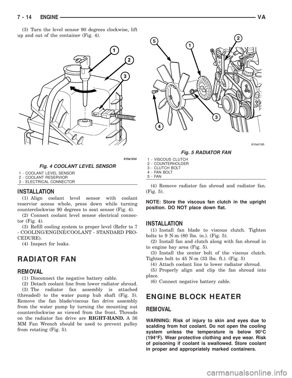
(3) Turn the level sensor 90 degrees clockwise, lift
up and out of the container (Fig. 4).
INSTALLATION
(1) Align coolant level sensor with coolant
reservior access whole, press down while turning
counterclockwise 90 degrees to seat sensor (Fig. 4).
(2) Connect coolant level sensor electrical connec-
tor (Fig. 4).
(3) Refill cooling system to proper level (Refer to 7
- COOLING/ENGINE/COOLANT - STANDARD PRO-
CEDURE).
(4) Inspect for leaks.
RADIATOR FAN
REMOVAL
(1) Disconnect the negative battery cable.
(2) Detach coolant line from lower radiator shroud.
(3) The radiator fan assembly is attached
(threaded) to the water pump hub shaft (Fig. 5).
Remove the fan blade/viscous fan drive assembly
from the water pump by turning the mounting nut
counterclockwise as viewed from the front. Threads
on the radiator fan drive areRIGHT-HAND.A36
MM Fan Wrench should be used to prevent pulley
from rotating (Fig. 5).(4) Remove radiator fan shroud and radiator fan.
(Fig. 5).
NOTE: Store the viscous fan clutch in the upright
position. DO NOT place down flat.
INSTALLATION
(1) Install fan blade to viscous clutch. Tighten
bolts to 9 N´m (80 lbs. in.). (Fig. 5).
(2) Install fan and clutch along with fan shroud in
to engine bay area (Fig. 5).
(3) Install the center bolt of the viscous clutch.
Tighten bolt to 45 N´m (33 lbs. ft.). (Fig. 5)
(4) Attach coolant line to lower radiator shroud.
(5) Properly align and clip the fan shroud into
place.
(6) Connect negative battery cable.
ENGINE BLOCK HEATER
REMOVAL
WARNING: Risk of injury to skin and eyes due to
scalding from hot coolant. Do not open the cooling
system unless the temperature is below 90ÉC
(194ÉF). Wear protective clothing and eye wear. Risk
of poisoning if coolant is swallowed. Store coolant
in proper and appropriately marked containers.
Fig. 4 COOLANT LEVEL SENSOR
1 - COOLANT LEVEL SENSOR
2 - COOLANT RESERVIOR
3 - ELECTRICAL CONNECTOR
Fig. 5 RADIATOR FAN
1 - VISCOUS CLUTCH
2 - COUNTERHOLDER
3 - CLUTCH BOLT
4 - FAN BOLT
5-FAN
7 - 14 ENGINEVA
Page 842 of 2305
(1) Disconnect the negative battery cable.
(2) Drain the cooling system.
(3) Record the location and snip the wire ties.
(4) Unscrew the engine block heater from the core
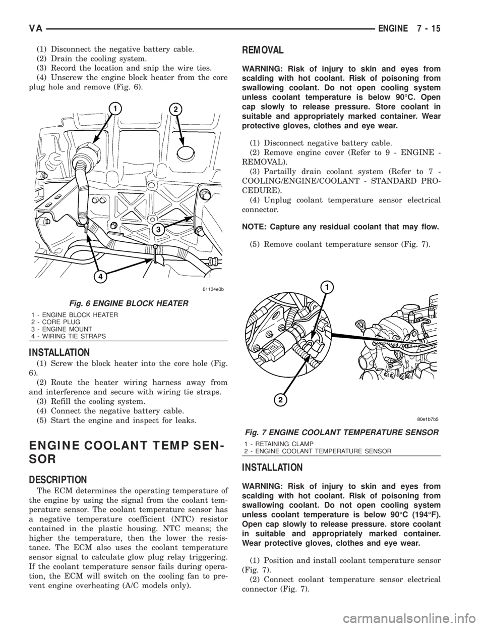
plug hole and remove (Fig. 6).
INSTALLATION
(1) Screw the block heater into the core hole (Fig.
6).
(2) Route the heater wiring harness away from
and interference and secure with wiring tie straps.
(3) Refill the cooling system.
(4) Connect the negative battery cable.
(5) Start the engine and inspect for leaks.
ENGINE COOLANT TEMP SEN-
SOR
DESCRIPTION
The ECM determines the operating temperature of
the engine by using the signal from the coolant tem-
perature sensor. The coolant temperature sensor has
a negative temperature coefficient (NTC) resistor
contained in the plastic housing. NTC means; the
higher the temperature, then the lower the resis-
tance. The ECM also uses the coolant temperature
sensor signal to calculate glow plug relay triggering.
If the coolant temperature sensor fails during opera-
tion, the ECM will switch on the cooling fan to pre-
vent engine overheating (A/C models only).
REMOVAL
WARNING: Risk of injury to skin and eyes from
scalding with hot coolant. Risk of poisoning from
swallowing coolant. Do not open cooling system
unless coolant temperature is below 90ÉC. Open
cap slowly to release pressure. Store coolant in
suitable and appropriately marked container. Wear
protective gloves, clothes and eye wear.
(1) Disconnect negative battery cable.
(2) Remove engine cover (Refer to 9 - ENGINE -
REMOVAL).
(3) Partailly drain coolant system (Refer to 7 -
COOLING/ENGINE/COOLANT - STANDARD PRO-
CEDURE).
(4) Unplug coolant temperature sensor electrical
connector.
NOTE: Capture any residual coolant that may flow.
(5) Remove coolant temperature sensor (Fig. 7).
INSTALLATION
WARNING: Risk of injury to skin and eyes from
scalding with hot coolant. Risk of poisoning from
swallowing coolant. Do not open cooling system
unless coolant temperature is below 90ÉC (194ÉF).
Open cap slowly to release pressure. store coolant
in suitable and appropriately marked container.
Wear protective gloves, clothes and eye wear.
(1) Position and install coolant temperature sensor
(Fig. 7).
(2) Connect coolant temperature sensor electrical
connector (Fig. 7).
Fig. 6 ENGINE BLOCK HEATER
1 - ENGINE BLOCK HEATER
2 - CORE PLUG
3 - ENGINE MOUNT
4 - WIRING TIE STRAPS
Fig. 7 ENGINE COOLANT TEMPERATURE SENSOR
1 - RETAINING CLAMP
2 - ENGINE COOLANT TEMPERATURE SENSOR
VAENGINE 7 - 15
Page 843 of 2305
(3) Refill coolant system to proper level with
proper mixture of coolant (Refer to 7 - COOLING/
ENGINE/COOLANT - STANDARD PROCEDURE).
(4) Install engine cover (Refer to 9 - ENGINE -
INSTALLATION).
(5) Connect negative battery cable.
WARNING: Use extreme caution when engine is
operating. Do not stand in a direct line with fan. do
not put your hands near pulleys, belts or fan. Do
not wear loose clothes.
(6) Start engine and inspect for leaks.
ENGINE COOLANT THERMO-
STAT
REMOVAL
WARNING: RISK OF INJURY TO SKIN AND EYES
FROM SCALDING WITH HOT COOLANT. RISK OF
POISONING FROM SWALLOWING COOLANT. DO
NOT OPEN COOLING SYSTEM UNLESS COOLANT
TEMPERATURE IS BELOW 90ÉC (194ÉF). OPEN CAP
SLOWLY TO RELEASE PRESSURE. STORE COOL-
ANT IN SUITABLE AND APPROPRIATELY MARKED
CONTAINER. WEAR PROTECTIVE GLOVES,
CLOTHES AND EYE WEAR.
NOTE: Inspect condition of all clamps and hoses,
replace as necessary.
(1) Disconnect negative battery cable.
(2) Partially drain engine coolant (Refer to 7 -
COOLING/ENGINE/COOLANT - STANDARD PRO-
CEDURE).
(3) Unplug connector, pull off locking element and
pull out coolant temperature sensor.
(4) Detach air intake hose at charge air distribu-
tion pipe.
(5) Detach coolant hoses at thermostat housing.
(6) Unscrew cap at oil filter housing.
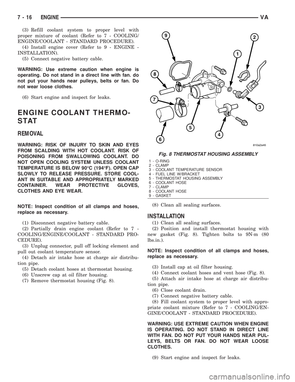
(7) Remove thermostat housing (Fig. 8).(8) Clean all sealing surfaces.
INSTALLATION
(1) Clean all sealing surfaces.
(2) Position and install thermostat housing with
new gasket (Fig. 8). Tighten bolts to 9N´m (80
lbs.in.).
NOTE: Inspect condition of all clamps and hoses,
replace as necessary.
(3) Install cap at oil filter housing.
(4) Connect coolant hoses and vent hose (Fig. 8).
(5) Attach air intake hose at charge air distribu-
tion pipe.
(6) Close coolant drain.
(7) Connect negative battery cable.
(8) Fill coolant system to proper level with appro-
priate coolant mixture (Refer to 7 - COOLING/EN-
GINE/COOLANT - STANDARD PROCEDURE).
WARNING: USE EXTREME CAUTION WHEN ENGINE
IS OPERATING. DO NOT STAND IN DIRECT LINE
WITH FAN. DO NOT PUT YOUR HANDS NEAR PUL-
LEYS, BELTS OR FAN. DO NOT WEAR LOOSE
CLOTHES.
(9) Start engine and inspect for leaks.
Fig. 8 THERMOSTAT HOUSING ASSEMBLY
1 - O-RING
2 - CLAMP
3 - COOLANT TEMPERATURE SENSOR
4 - FUEL LINE W/BRACKET
5 - THERMOSTAT HOUSING ASSEMBLY
6 - COOLANT HOSE
7 - CLAMP
8 - COOLANT HOSE
9 - GASKET
7 - 16 ENGINEVA
Page 844 of 2305
FAN DRIVE VISCOUS CLUTCH
REMOVAL
(1) For fan drive viscous clutch removal refer to
(Refer to 7 - COOLING/ENGINE/RADIATOR FAN -
REMOVAL).
INSTALLATION
(1) For fan drive viscous clutch installation refer to
(Refer to 7 - COOLING/ENGINE/RADIATOR FAN -
INSTALLATION).
RADIATOR
REMOVAL
WARNING: RISK OF INJURY TO SKIN AND EYES
FROM SCALDING WITH HOT COOLANT. RISK OF
POISONING FROM SWALLOWING COOLANT. DO
NOT OPEN COOLING SYSTEM UNLESS COOLANT
TEMPERATURE IS BELOW 90ÉC (194ÉF). OPEN CAP
SLOWLY TO RELEASE PRESSURE. STORE COOL-
ANT IN SUITABLE AND APPROPRIATELY MARKED
CONTAINER. WEAR PROTECTIVE GLOVES,
CLOTHES AND EYE WEAR.
NOTE: Capture all residual fluid spillage and store
in suitably marked containers. Inspect condition of
all clamps and hoses, replace as necessary.
(1) Drain coolant from radiator only (Refer to 7 -
COOLING/ENGINE/COOLANT - STANDARD PRO-
CEDURE).
(2) Remove headlamps.
(3) Remove front cross member together with front
grille.
(4) Remove front bumper.
(5) Remove bolts holding air charge hose to sheet
metal and intercooler.
(6) Detach air intake pipe at the body (Fig. 9).
(7) Detach both coolant hoses at the coolant reser-
voir (Fig. 9).
VAENGINE 7 - 17
Page 845 of 2305
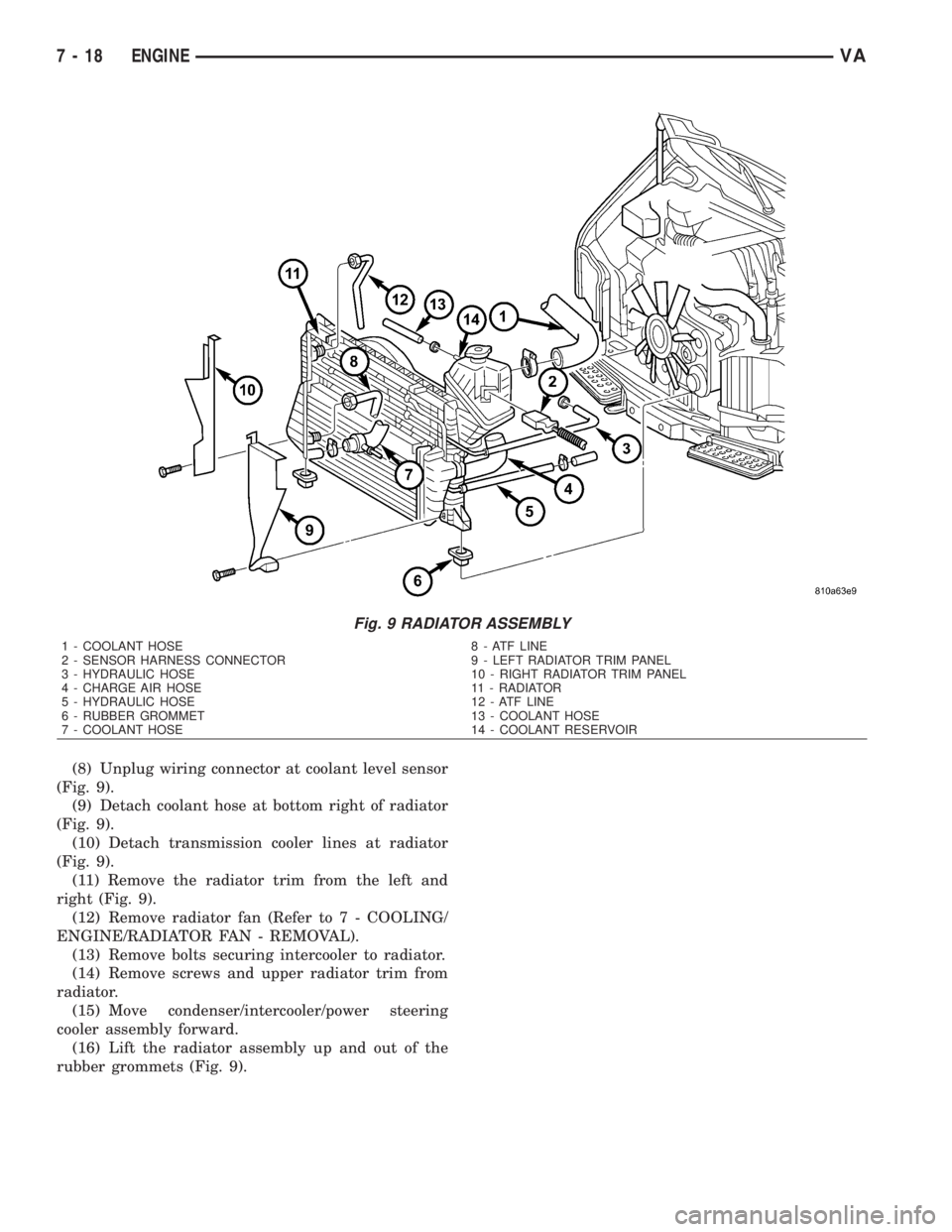
(8) Unplug wiring connector at coolant level sensor
(Fig. 9).
(9) Detach coolant hose at bottom right of radiator
(Fig. 9).
(10) Detach transmission cooler lines at radiator
(Fig. 9).
(11) Remove the radiator trim from the left and
right (Fig. 9).
(12) Remove radiator fan (Refer to 7 - COOLING/
ENGINE/RADIATOR FAN - REMOVAL).
(13) Remove bolts securing intercooler to radiator.
(14) Remove screws and upper radiator trim from
radiator.
(15) Move condenser/intercooler/power steering
cooler assembly forward.
(16) Lift the radiator assembly up and out of the
rubber grommets (Fig. 9).
Fig. 9 RADIATOR ASSEMBLY
1 - COOLANT HOSE 8 - ATF LINE
2 - SENSOR HARNESS CONNECTOR 9 - LEFT RADIATOR TRIM PANEL
3 - HYDRAULIC HOSE 10 - RIGHT RADIATOR TRIM PANEL
4 - CHARGE AIR HOSE 11 - RADIATOR
5 - HYDRAULIC HOSE 12 - ATF LINE
6 - RUBBER GROMMET 13 - COOLANT HOSE
7 - COOLANT HOSE 14 - COOLANT RESERVOIR
7 - 18 ENGINEVA
Page 846 of 2305
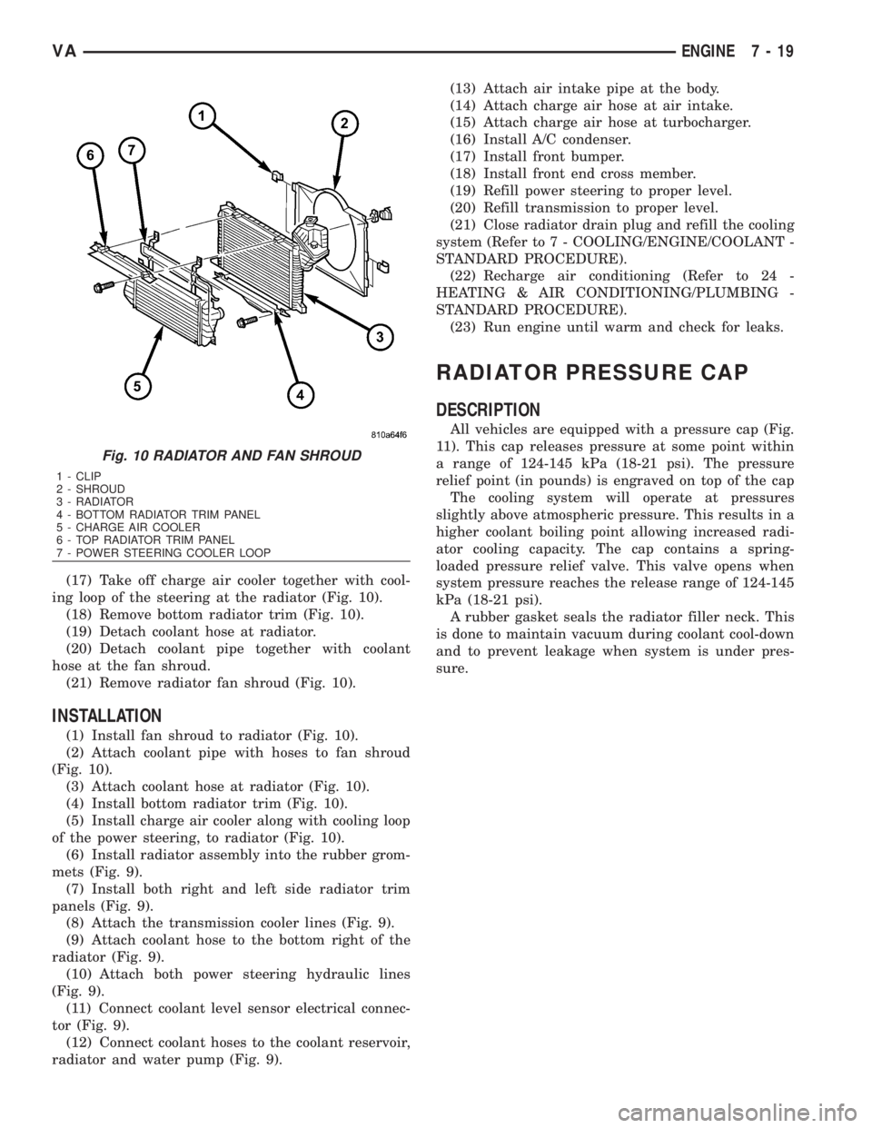
(17) Take off charge air cooler together with cool-
ing loop of the steering at the radiator (Fig. 10).
(18) Remove bottom radiator trim (Fig. 10).
(19) Detach coolant hose at radiator.
(20) Detach coolant pipe together with coolant
hose at the fan shroud.
(21) Remove radiator fan shroud (Fig. 10).
INSTALLATION
(1) Install fan shroud to radiator (Fig. 10).
(2) Attach coolant pipe with hoses to fan shroud
(Fig. 10).
(3) Attach coolant hose at radiator (Fig. 10).
(4) Install bottom radiator trim (Fig. 10).
(5) Install charge air cooler along with cooling loop
of the power steering, to radiator (Fig. 10).
(6) Install radiator assembly into the rubber grom-
mets (Fig. 9).
(7) Install both right and left side radiator trim
panels (Fig. 9).
(8) Attach the transmission cooler lines (Fig. 9).
(9) Attach coolant hose to the bottom right of the
radiator (Fig. 9).
(10) Attach both power steering hydraulic lines
(Fig. 9).
(11) Connect coolant level sensor electrical connec-
tor (Fig. 9).
(12) Connect coolant hoses to the coolant reservoir,
radiator and water pump (Fig. 9).(13) Attach air intake pipe at the body.
(14) Attach charge air hose at air intake.
(15) Attach charge air hose at turbocharger.
(16) Install A/C condenser.
(17) Install front bumper.
(18) Install front end cross member.
(19) Refill power steering to proper level.
(20) Refill transmission to proper level.
(21) Close radiator drain plug and refill the cooling
system (Refer to 7 - COOLING/ENGINE/COOLANT -
STANDARD PROCEDURE).
(22) Recharge air conditioning (Refer to 24 -
HEATING & AIR CONDITIONING/PLUMBING -
STANDARD PROCEDURE).
(23) Run engine until warm and check for leaks.
RADIATOR PRESSURE CAP
DESCRIPTION
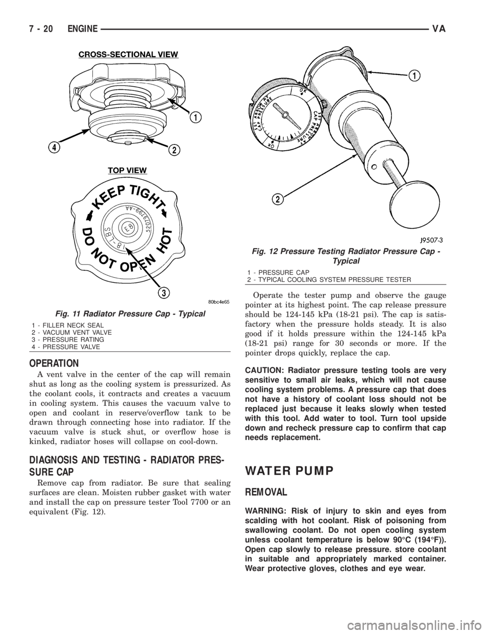
All vehicles are equipped with a pressure cap (Fig.
11). This cap releases pressure at some point within
a range of 124-145 kPa (18-21 psi). The pressure
relief point (in pounds) is engraved on top of the cap
The cooling system will operate at pressures
slightly above atmospheric pressure. This results in a
higher coolant boiling point allowing increased radi-
ator cooling capacity. The cap contains a spring-
loaded pressure relief valve. This valve opens when
system pressure reaches the release range of 124-145
kPa (18-21 psi).
A rubber gasket seals the radiator filler neck. This
is done to maintain vacuum during coolant cool-down
and to prevent leakage when system is under pres-
sure.
Fig. 10 RADIATOR AND FAN SHROUD
1 - CLIP
2 - SHROUD
3 - RADIATOR
4 - BOTTOM RADIATOR TRIM PANEL
5 - CHARGE AIR COOLER
6 - TOP RADIATOR TRIM PANEL
7 - POWER STEERING COOLER LOOP
VAENGINE 7 - 19
Page 847 of 2305
OPERATION
A vent valve in the center of the cap will remain
shut as long as the cooling system is pressurized. As
the coolant cools, it contracts and creates a vacuum
in cooling system. This causes the vacuum valve to
open and coolant in reserve/overflow tank to be
drawn through connecting hose into radiator. If the
vacuum valve is stuck shut, or overflow hose is
kinked, radiator hoses will collapse on cool-down.
DIAGNOSIS AND TESTING - RADIATOR PRES-
SURE CAP
Remove cap from radiator. Be sure that sealing
surfaces are clean. Moisten rubber gasket with water
and install the cap on pressure tester Tool 7700 or an
equivalent (Fig. 12).Operate the tester pump and observe the gauge
pointer at its highest point. The cap release pressure
should be 124-145 kPa (18-21 psi). The cap is satis-
factory when the pressure holds steady. It is also
good if it holds pressure within the 124-145 kPa
(18-21 psi) range for 30 seconds or more. If the
pointer drops quickly, replace the cap.
CAUTION: Radiator pressure testing tools are very
sensitive to small air leaks, which will not cause
cooling system problems. A pressure cap that does
not have a history of coolant loss should not be
replaced just because it leaks slowly when tested
with this tool. Add water to tool. Turn tool upside
down and recheck pressure cap to confirm that cap
needs replacement.
WATER PUMP
REMOVAL
WARNING: Risk of injury to skin and eyes from
scalding with hot coolant. Risk of poisoning from
swallowing coolant. Do not open cooling system
unless coolant temperature is below 90ÉC (194ÉF)).
Open cap slowly to release pressure. store coolant
in suitable and appropriately marked container.
Wear protective gloves, clothes and eye wear.
Fig. 11 Radiator Pressure Cap - Typical
1 - FILLER NECK SEAL
2 - VACUUM VENT VALVE
3 - PRESSURE RATING
4 - PRESSURE VALVE
Fig. 12 Pressure Testing Radiator Pressure Cap -
Typical
1 - PRESSURE CAP
2 - TYPICAL COOLING SYSTEM PRESSURE TESTER
7 - 20 ENGINEVA
Page 848 of 2305
NOTE: Inspect condition of all clamps and hoses,
replace as necessary.
(1) Disconnect the negative battery cable.
(2) Drain cooling system (Refer to 7 - COOLING/
ENGINE/COOLANT - STANDARD PROCEDURE).
(3) Remove viscous fan clutch.
(4) Detach fuel lines from the brackets at the
water pump.
(5) Detach the coolant hoses at the water pump
(Fig. 13).
VAENGINE 7 - 21
Page 849 of 2305
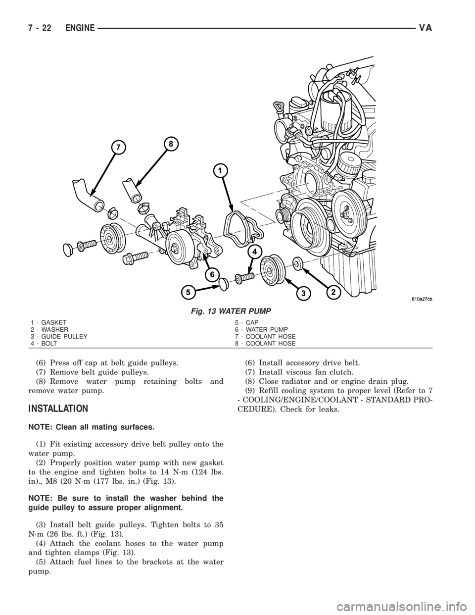
(6) Press off cap at belt guide pulleys.
(7) Remove belt guide pulleys.
(8) Remove water pump retaining bolts and
remove water pump.
INSTALLATION
NOTE: Clean all mating surfaces.
(1) Fit existing accessory drive belt pulley onto the
water pump.
(2) Properly position water pump with new gasket
to the engine and tighten bolts to 14 N´m (124 lbs.
in)., M8 (20 N´m (177 lbs. in.) (Fig. 13).
NOTE: Be sure to install the washer behind the
guide pulley to assure proper alignment.
(3) Install belt guide pulleys. Tighten bolts to 35
N´m (26 lbs. ft.) (Fig. 13).
(4) Attach the coolant hoses to the water pump
and tighten clamps (Fig. 13).
(5) Attach fuel lines to the brackets at the water
pump.(6) Install accessory drive belt.
(7) Install viscous fan clutch.
(8) Close radiator and or engine drain plug.
(9) Refill cooling system to proper level (Refer to 7
- COOLING/ENGINE/COOLANT - STANDARD PRO-
CEDURE). Check for leaks.
Fig. 13 WATER PUMP
1 - GASKET 5 - CAP
2 - WASHER 6 - WATER PUMP
3 - GUIDE PULLEY 7 - COOLANT HOSE
4 - BOLT 8 - COOLANT HOSE
7 - 22 ENGINEVA
Page 850 of 2305
AUDIO / VIDEO
TABLE OF CONTENTS
page page
AUDIO
SPECIAL TOOLS
AUDIO...............................1
ANTENNA BODY & CABLE
REMOVAL.............................1
INSTALLATION..........................1
INSTRUMENT PANEL ANTENNA CABLE
REMOVAL.............................2INSTALLATION..........................2
RADIO
REMOVAL.............................2
INSTALLATION..........................2
SPEAKER
REMOVAL.............................2
INSTALLATION..........................3
AUDIO
SPECIAL TOOLS
AUDIO
SPECIAL TOOL CROSS REFERENCE CHART
MB
TOOL #MILLER
TOOL #DESCRIPTION
000 589
88 63 009241 RADIO EXTRACTION
TOOL
ANTENNA BODY & CABLE
REMOVAL
(1) Disconnect and isolate the battery negative
cable.
(2) Remove the portion of the headliner over the
front seat passengers (Refer to 23 - BODY/INTERI-
OR/HEADLINER - REMOVAL).
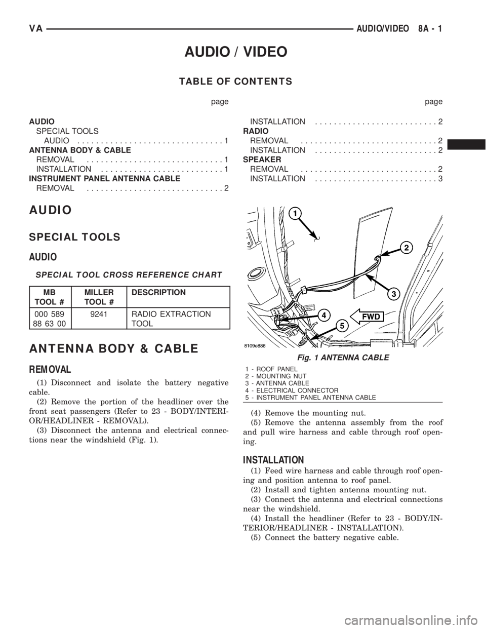
(3) Disconnect the antenna and electrical connec-
tions near the windshield (Fig. 1).(4) Remove the mounting nut.
(5) Remove the antenna assembly from the roof
and pull wire harness and cable through roof open-
ing.
INSTALLATION
(1) Feed wire harness and cable through roof open-
ing and position antenna to roof panel.
(2) Install and tighten antenna mounting nut.
(3) Connect the antenna and electrical connections
near the windshield.
(4) Install the headliner (Refer to 23 - BODY/IN-
TERIOR/HEADLINER - INSTALLATION).
(5) Connect the battery negative cable.
Fig. 1 ANTENNA CABLE
1 - ROOF PANEL
2 - MOUNTING NUT
3 - ANTENNA CABLE
4 - ELECTRICAL CONNECTOR
5 - INSTRUMENT PANEL ANTENNA CABLE
VAAUDIO/VIDEO 8A - 1