sensor MERCEDES-BENZ SPRINTER 2015 MY15 Operator’s Manual
[x] Cancel search | Manufacturer: MERCEDES-BENZ, Model Year: 2015, Model line: SPRINTER, Model: MERCEDES-BENZ SPRINTER 2015Pages: 334, PDF Size: 5.94 MB
Page 313 of 334

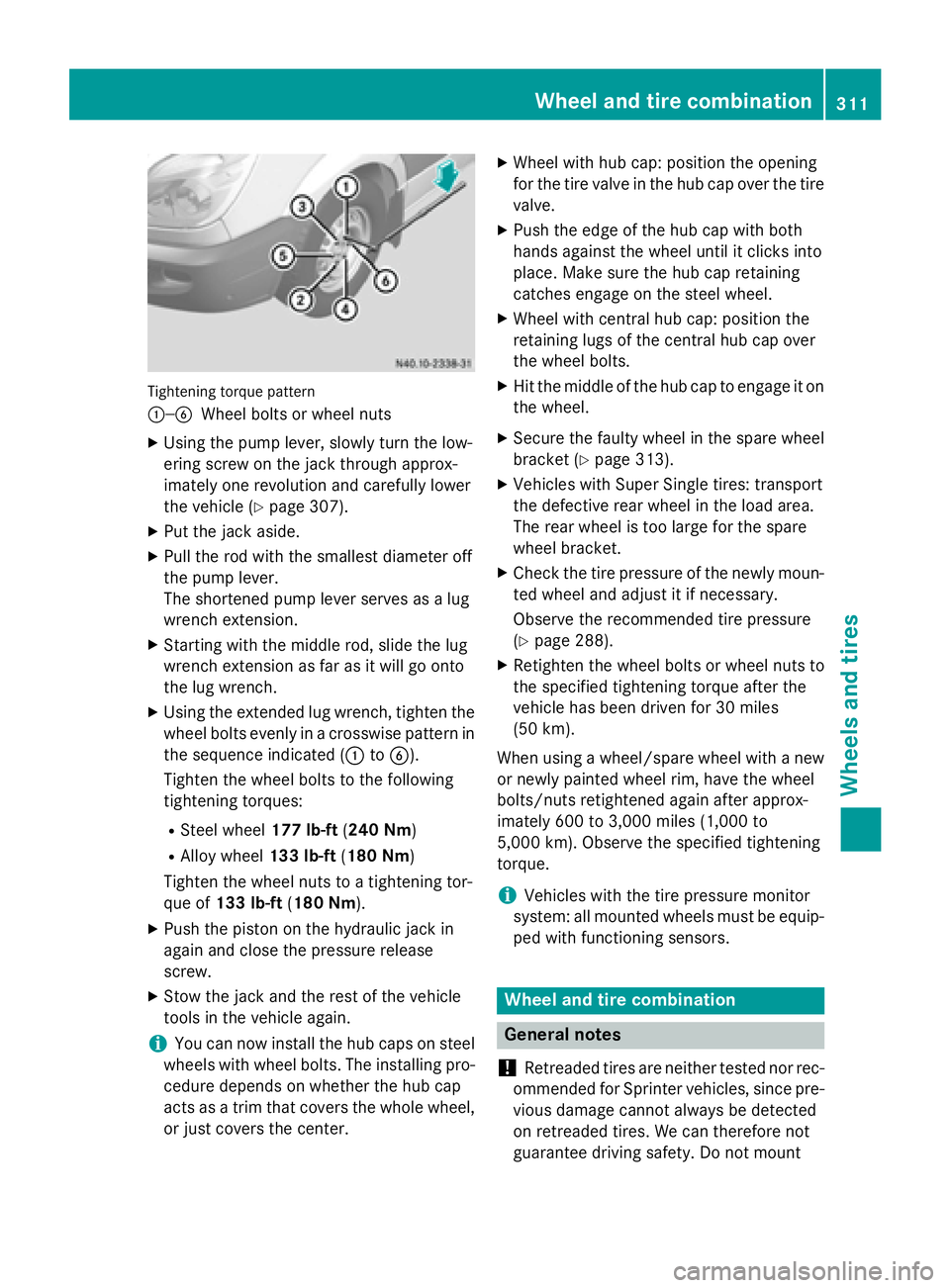
Tightening torque pattern
0043—0084
Wheel bolts or wheel nuts
X Using the pump lever, slowly turn the low-
ering screw on the jack through approx-
imately one revolution and carefully lower
the vehicle (Y page 307).
X Put the jack aside.
X Pull the rod with the smallest diameter off
the pump lever.
The shortened pump lever serves as a lug
wrench extension.
X Starting with the middle rod, slide the lug
wrench extension as far as it will go onto
the lug wrench.
X Using the extended lug wrench, tighten the
wheel bolts evenly in a crosswise pattern in the sequence indicated (0043 to0084).
Tighten the wheel bolts to the following
tightening torques:
R Steel wheel 177 lb-ft(240 Nm)
R Alloy wheel 133 lb-ft(180 Nm)
Tighten the wheel nuts to a tightening tor-
que of 133 lb-ft (180 Nm).
X Push the piston on the hydraulic jack in
again and close the pressure release
screw.
X Stow the jack and the rest of the vehicle
tools in the vehicle again.
i You can now install the hub caps on steel
wheels with wheel bolts. The installing pro-
cedure depends on whether the hub cap
acts as a trim that covers the whole wheel,
or just covers the center. X
Wheel with hub cap: position the opening
for the tire valve in the hub cap over the tire
valve.
X Push the edge of the hub cap with both
hands against the wheel until it clicks into
place. Make sure the hub cap retaining
catches engage on the steel wheel.
X Wheel with central hub cap: position the
retaining lugs of the central hub cap over
the wheel bolts.
X Hit the middle of the hub cap to engage it on
the wheel.
X Secure the faulty wheel in the spare wheel
bracket (Y page 313).
X Vehicles with Super Single tires: transport
the defective rear wheel in the load area.
The rear wheel is too large for the spare
wheel bracket.
X Check the tire pressure of the newly moun-
ted wheel and adjust it if necessary.
Observe the recommended tire pressure
(Y page 288).
X Retighten the wheel bolts or wheel nuts to
the specified tightening torque after the
vehicle has been driven for 30 miles
(50 km).
When using a wheel/spare wheel with a new
or newly painted wheel rim, have the wheel
bolts/nuts retightened again after approx-
imately 600 to 3,000 miles (1,000 to
5,000 km). Observe the specified tightening
torque.
i Vehicles with the tire pressure monitor
system: all mounted wheels must be equip- ped with functioning sensors. Wheel and tire combination
General notes
! Retreaded tires are neither tested nor rec-
ommended for Sprinter vehicles, since pre-
vious damage cannot always be detected
on retreaded tires. We can therefore not
guarantee driving safety. Do not mount Wheel and tire combination
311Wheels and tires Z
Page 315 of 334

i
If you have mounted a spare wheel, the
tire pressure monitor (Y page 291) will not
function for this wheel. The spare wheel is
not equipped with a sensor for monitoring
tire pressure. Removing and installing the spare
wheel
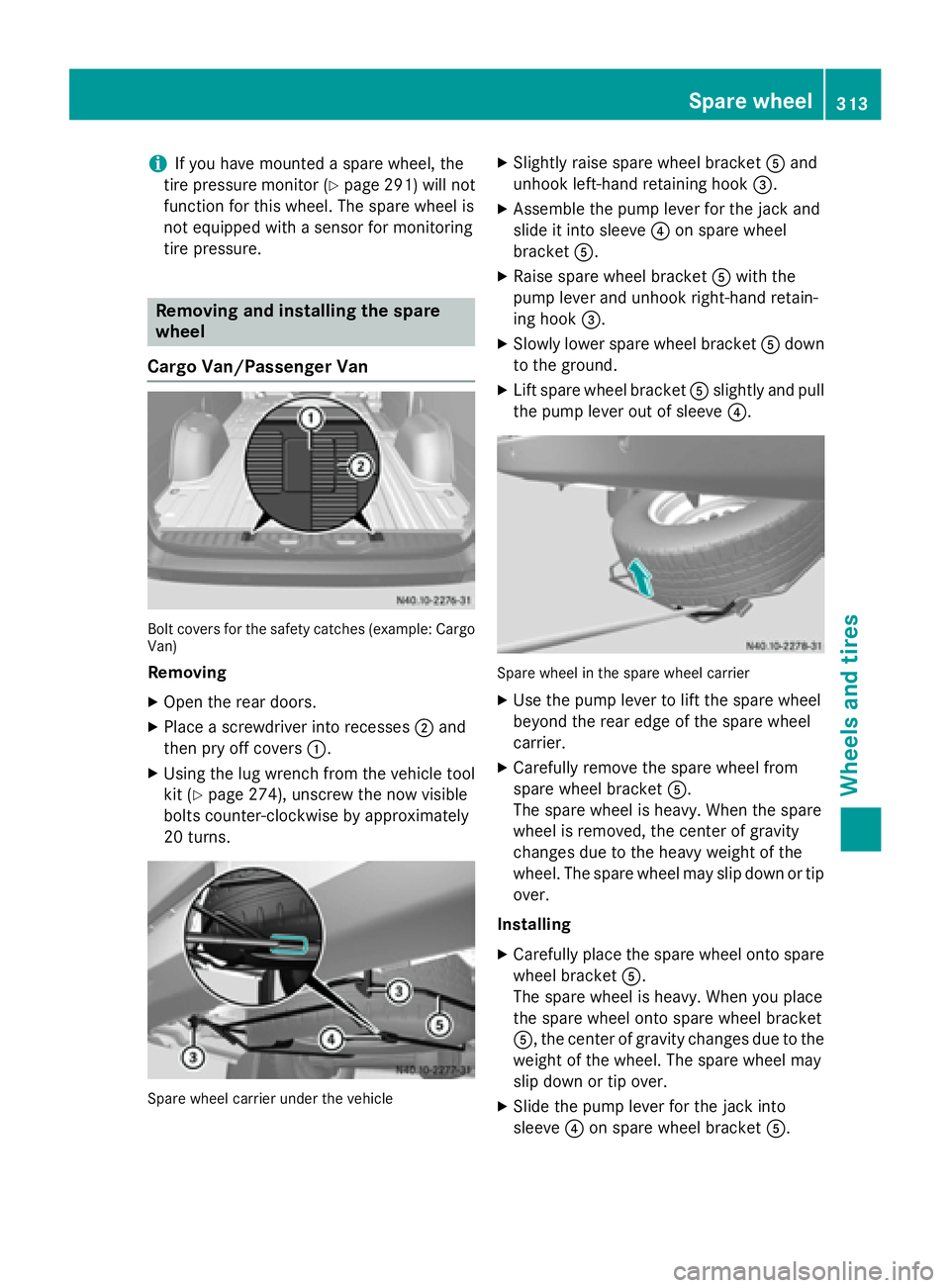
Cargo Van/Passenger Van Bolt covers for the safety catches (example: Cargo
Van)
Removing
X Open the rear doors.
X Place a screwdriver into recesses 0044and
then pry off covers 0043.
X Using the lug wrench from the vehicle tool
kit (Y page 274), unscrew the now visible
bolts counter-clockwise by approximately
20 turns. Spare wheel carrier under the vehicle X
Slightly raise spare wheel bracket 0083and
unhook left-hand retaining hook 0087.
X Assemble the pump lever for the jack and
slide it into sleeve 0085on spare wheel
bracket 0083.
X Raise spare wheel bracket 0083with the
pump lever and unhook right-hand retain-
ing hook 0087.
X Slowly lower spare wheel bracket 0083down
to the ground.
X Lift spare wheel bracket 0083slightly and pull
the pump lever out of sleeve 0085. Spare wheel in the spare wheel carrier
X Use the pump lever to lift the spare wheel
beyond the rear edge of the spare wheel
carrier.
X Carefully remove the spare wheel from
spare wheel bracket 0083.
The spare wheel is heavy. When the spare
wheel is removed, the center of gravity
changes due to the heavy weight of the
wheel. The spare wheel may slip down or tip over.
Installing X Carefully place the spare wheel onto spare
wheel bracket 0083.
The spare wheel is heavy. When you place
the spare wheel onto spare wheel bracket
0083, the center of gravity changes due to the
weight of the wheel. The spare wheel may
slip down or tip over.
X Slide the pump lever for the jack into
sleeve 0085on spare wheel bracket 0083. Spare wheel
313Wheels and tires Z
Page 318 of 334

Vehicle electronics
Tampering with the engine electron-
ics G
WARNING
Always have work on the engine electronics
and related components carried out at a quali- fied specialist workshop. Otherwise, the vehi-cle's operating safety could be affected.
! Only have engine electronics and the cor-
responding parts, such as control units,
sensors or connector leads, serviced in a
qualified specialist workshop. Otherwise,
the vehicle parts may wear more quickly.
This can lead to loss of the New Vehicle
Limited Warranty. Installing electrical or electronic
equipment
G
WARNING
You and others may damage your health due
to excessive electromagnetic radiation. By
using an external antenna, the possible health risks of electromagnetic fields, which are
under discussion among the scientific com-
munity, should be largely prevented.
Therefore, only have the exterior antenna
installed at a qualified specialist workshop.
Electrical and electronic devices may have a
detrimental effect on both the comfort and
the operating safety of the vehicle. If equip-
ment of this kind is installed, its electromag-
netic compatibility must be checked and veri-
fied.
If these devices are linked to functions asso-
ciated with resistance to interference, they
must have type approval. This applies to the
device or its interfaces to the vehicle elec-
tronics, e.g. charging brackets.
A telephone or two-way radio to be installed in
the vehicle must be approved. Further infor-
mation can be obtained from any Sprinter
Dealer. For operation of mobile phones and two-way
radios, Mercedes Benz recommends connec- tion to an approved exterior antenna. This is
the only way to ensure optimum reception
quality inside the vehicle and to minimize
mutual interference between the vehicle elec-
tronics, mobile phones and two-way radios.
The transmission output of the mobile phone
or two-way radio may not exceed the follow-
ing maximum transmission output (PEAK): Frequency range Maximum trans-
mission output
(PEAK) Shortwave
(f < 50 MHz) 100 W
4 m waveband 30 W
2 m waveband 50 W
Trunked radio/Tetra 35 W
70 cm waveband 35 W
GSM/UMTS/LTE 10 W
Identification plates
Vehicle identification plate with vehi-
cle identification number (VIN)
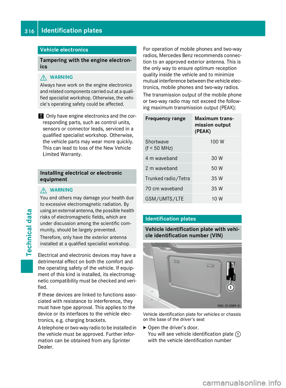
Vehicle identification plate for vehicles or chassis
on the base of the driver's seat
X Open the driver’s door.
You will see vehicle identification plate 0043
with the vehicle identification number 316
Identification platesTechnical data