clock MERCEDES-BENZ SPRINTER 2019 MY19 with 7” screen
[x] Cancel search | Manufacturer: MERCEDES-BENZ, Model Year: 2019, Model line: SPRINTER, Model: MERCEDES-BENZ SPRINTER 2019Pages: 354, PDF Size: 6.15 MB
Page 73 of 354

#
Tounlo ck:pull lo cking pin 2upwards man‐
ually or use the cent ral locking button to
unlo ckthe sliding door (/ page44). #
Press button 1or pull outside handle 3.
The sliding door opens or closes. #
Press button 1again or pull outside handle
3.
The sliding door stops moving. Un
locking the electric sliding door manually If
th ere has been a malfunction or if the battery
has been disconnected, you can use release
cat ch2 todisconnect the sliding door from the
electric mo tor.Then, you can open or close the
door manually. #
Vehicles with comple tesliding door trim:
re mo vethe co ver from release cat ch2.
Service ope ration is accessible. #
Todisconnect the sliding door from the
electric mo tor:turn release cat ch2 180°
clockwise.
The "MAN" position is set. #
Tounlo ck:pull lo cking pin 3upwards man‐
ually or use the cent ral locking button to
unlo ckthe sliding door (/ page44). #
Press button 1. #
Open or close the sliding door with the out‐
side/inside door handle. #
Toconnect the sliding door tothe electric
mo tor:turn release cat ch2 180° counter-
clockwise.
The "AUTO" position is set. #
Adjust the sliding door (/ page 49).
If it is not possible to rectify the malfunction: #
Visit a qualified specialist workshop. Re
setting the electric sliding door Sliding door buttons on
the center console Sliding door button on
the door sill (B-pillar)
Yo u must reset the sliding door if there has been
a malfunction or a voltage supply inter ruption. Opening and closing
49
Page 75 of 354
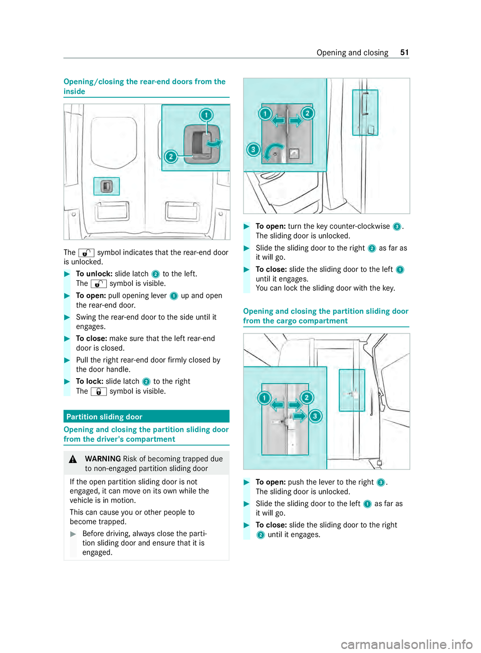
Opening/closing
there ar-end doors from the
inside The
0036 symbol indicates that there ar-end door
is unlo cked. #
Tounlo ck:slide latch 2tothe left.
The 0036 symbol is visible. #
Toopen: pull opening le ver1 up and open
th ere ar-end door. #
Swing there ar-end door tothe side until it
engages. #
Toclose: make sure that the left rear-end
door is closed. #
Pull theright rear-end door firm ly closed by
th e door handle. #
Tolock: slide latch 2totheright
The 0037 symbol is visible. Pa
rtition sliding door Opening and closing
the pa rtition sliding door
from the driver's compa rtment &
WARNING Risk of becoming trapped due
to non-engaged pa rtition sliding door
If th e open partition sliding door is not
engaged, it can mo veon its own while the
ve hicle is in motion.
This can cause you or other people to
become trapped. #
Before driving, alw ays close the parti‐
tion sliding door and ensure that it is
engaged. #
Toopen: turntheke y counter-clockwise 3.
The sliding door is unloc ked. #
Slide the sliding door totheright 2asfar as
it will go. #
Toclose: slidethe sliding door tothe left 1
until it engages.
Yo u can lock the sliding door with thekey. Opening and closing
the pa rtition sliding door
from the cargo compa rtment #
Toopen: pushthe le verto theright 3.
The sliding door is unloc ked. #
Slide the sliding door tothe left 1asfar as
it will go. #
Toclose: slidethe sliding door totheright
2 until it engages. Opening and closing
51
Page 109 of 354
#
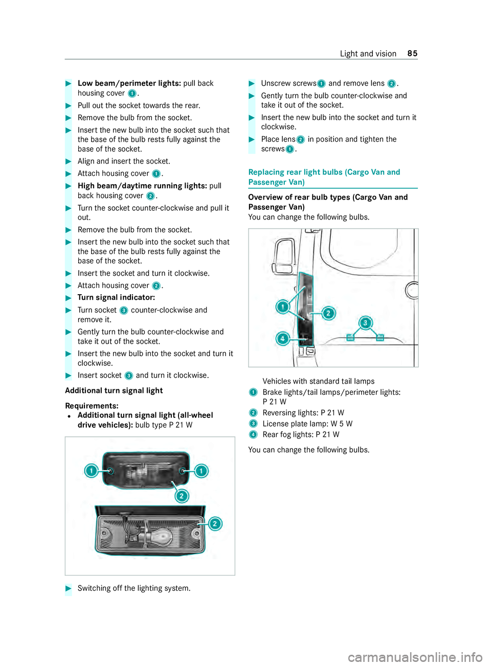
Low beam/perime ter lights: pull back
housing co ver1. #
Pull out the soc ketto wa rdsth ere ar. #
Remo vethe bulb from the soc ket. #
Inse rtthe new bulb into the soc ket su chthat
th e base of the bulb rests fully against the
base of the soc ket. #
Align and insert the soc ket. #
Attach housing co ver1. #
High beam/daytime running lights: pull
back housing co ver2. #
Turn the soc ket counter-clo ckwise and pull it
out. #
Remo vethe bulb from the soc ket. #
Inse rtthe new bulb into the soc ket su chthat
th e base of the bulb rests fully against the
base of the soc ket. #
Inse rtthe soc ket and turn it clo ckwise. #
Attach housing co ver2. #
Turn signal indicator: #
Turn soc ket3 counter-clo ckwise and
re mo veit. #
Gently turn the bulb counter-clockwise and
ta ke it out of the soc ket. #
Inse rtthe new bulb into the soc ket and turn it
clo ckwise. #
Insert soc ket3 and turn it clo ckwise.
Ad ditional turn signal light
Re quirements:
R Ad
ditional turn signal light (all-wheel
drive vehicles): bulb type P 21 W #
Switching off the lighting sy stem. #
Unscr ewscrews 1and remo velens 2. #
Gently turn the bulb counter-clockwise and
ta ke it out of the soc ket. #
Inse rtthe new bulb into the soc ket and turn it
clo ckwise. #
Place lens 2in position and tigh tenthe
scr ews 1. Re
placing rear light bulbs (Cargo Van and
Pa ssenger Van) Overview of
rear bulb types (Cargo Van and
Pa ssenger Van)
Yo u can change thefo llowing bulbs. Ve
hicles with standard tail lamps
1 Brake lights/tail lamps/pe rime ter lights:
P 21 W
2 Reversing lights: P 21 W
3 License plate lamp: W 5 W
4 Rear fog lights: P 21 W
Yo u can change thefo llowing bulbs. Light and vision
85
Page 110 of 354
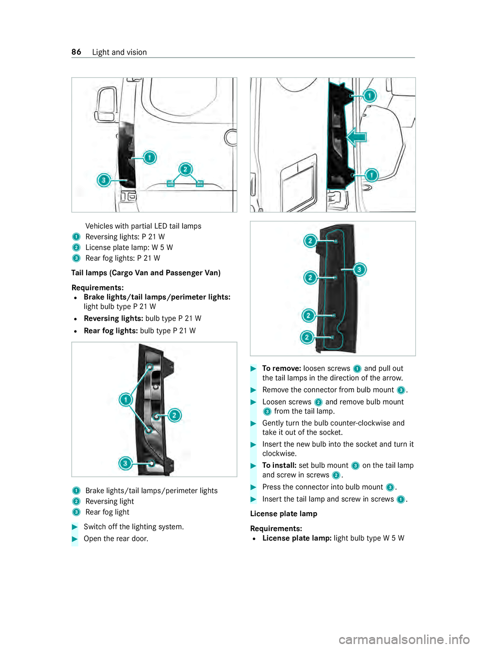
Ve
hicles with partial LED tail lamps
1 Reversing lights: P 21 W
2 License plate lamp: W 5 W
3 Rear fog lights: P 21 W
Ta il lamps (Cargo Van and Passenger Van)
Re quirements:
R Brake lights/tail lamps/perime
ter lights:
light bulb type P 21 W
R Reversing lights: bulb type P 21 W
R Rear fog lights: bulb type P 21 W 1
Brake lights/tail la mps/perime ter lights
2 Reversing light
3 Rear fog light #
Switch off the lighting sy stem. #
Open there ar door. #
Toremo ve:loosen scr ews1 and pull out
th eta il lamps in the direction of the ar row. #
Remo vethe connector from bulb mount 3. #
Loosen scr ews2 and remo vebulb mount
3 from theta il lamp. #
Gently turn the bulb counter-clockwise and
ta ke it out of the soc ket. #
Inse rtthe new bulb into the soc ket and turn it
clo ckwise. #
Toinstall: set bulb mount 3ontheta il lamp
and scr ewin scr ews2. #
Press the connector into bulb mount 3. #
Insert theta il lamp and scr ewin scr ews1.
License plate lamp
Re quirements:
R License plate lamp: light bulb type W 5 W86
Light and vision
Page 111 of 354
#
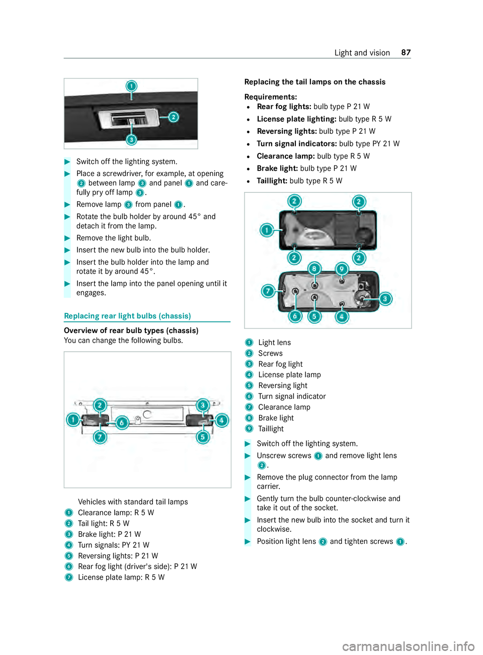
Switch off the lighting sy stem. #
Place a scr ewdriver, forex ample, at opening
2 between lamp 3and panel 1and care‐
fully pry off lamp 3. #
Remo velamp 3from panel 1. #
Rotate the bulb holder byaround 45° and
de tach it from the lamp. #
Remo vethe light bulb. #
Insert the new bulb into the bulb holder. #
Insert the bulb holder into the lamp and
ro tate itby around 45°. #
Insert the lamp into the panel opening until it
engages. Re
placing rear light bulbs (chassis) Overview of
rear bulb types (chassis)
Yo u can change thefo llowing bulbs. Ve
hicles with standard tail lamps
1 Clearance lamp: R 5 W
2 Tail light: R 5 W
3 Brake light: P 21 W
4 Turn signals: PY 21 W
5 Reversing lights: P 21 W
6 Rear fog light (driver's side): P 21 W
7 License plate lamp: R 5 W Re
placing the tail lamps on the chassis
Re quirements:
R Rear fog lights: bulb type P 21 W
R License pla telighting: bulb type R 5 W
R Reversing lights: bulb type P 21 W
R Turn signal indicators: bulb type PY21 W
R Clearance lamp: bulb type R 5 W
R Brake light: bulb type P21 W
R Taillight: bulb type R 5 W 1
Light lens
2 Screws
3 Rear fog light
4 License plate lamp
5 Reversing light
6 Turn signal indicator
7 Cleara nce lamp
8 Brake light
9 Taillight #
Swit choff the lighting sy stem. #
Unscr ewscrews1 and remo velight lens
2. #
Remo vethe plug connector from the lamp
car rier. #
Gently turn the bulb counter-clockwise and
ta ke it out of the soc ket. #
Inse rtthe new bulb into the soc ket and turn it
clo ckwise. #
Position light lens 2and tighten scr ews1. Light and vision
87
Page 150 of 354
*
NO
TEDo not use diesel torefuel vehicles
with a gasoline engine. If
yo u acciden tally refuel with the wrong fuel:
R Do not switch the ignition on. Otherwise
fuel can enter the engine.
Even small amounts of the wrong fuel
could result in damage tothe fuel sy stem
and the engine. The repair costs are high. #
Consult a qualified specialist workshop. #
Have the fuel tank and fuel lines drained
comple tely. *
NO
TEDo not use gasoline torefuel vehi‐
cles with a diesel engine. If
yo u acciden tally refuel with the wrong fuel:
R Do not switch the ignition on. Otherwise,
fuel can enter the fuel sy stem.
Even small amounts of the wrong fuel
could result in damage tothe fuel sy stem
and the engine. The repair costs are high. #
Consult a qualified specialist workshop. #
Have the fuel tank and fuel lines drained
comple tely. *
NO
TEDama getothe fuel sy stem caused
by ove rfilled fuel tanks. #
Only fill th e fuel tank until the pump
nozzle switches off. *
NO
TEFuel may spr ayout when you
re mo vethe fuel pump nozzle. #
Only fill th e fuel tank until the pump
nozzle switches off. *
NO
TEDama getopainted sur faces due to
fuel #
Do not spill any fuel on painted sur fa‐
ces. +
ENVI
RONMENTAL NOTEEnvironmental
damage due toimproper handling of fuel If fuels are handled improperly,
they pose a
danger topersons and the environment. #
Do not allow fuels torun into the sew‐
age sy stem, the sur face wate rs,the
ground water or into the ground. Re
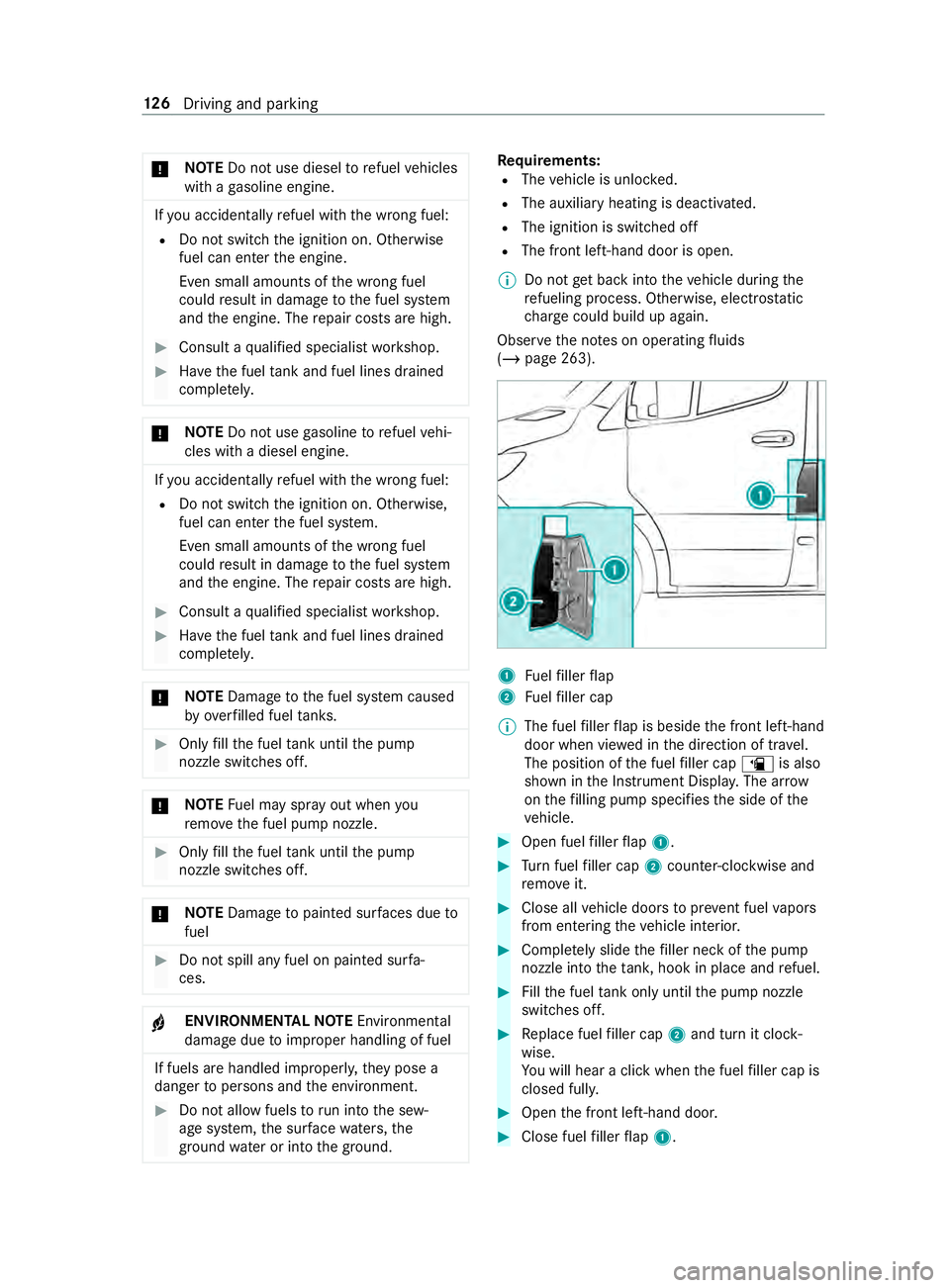
quirements:
R The vehicle is unloc ked.
R The auxiliary heating is deactivated.
R The ignition is switched off
R The front left-hand door is open.
% Do not
get ba ckinto theve hicle during the
re fueling process. Otherwise, electros tatic
ch arge could build up again.
Obser vethe no tes on operating fluids
(/ page 263). 1
Fuelfiller flap
2 Fuelfiller cap
% The fuel
filler flap is beside the front left-hand
door when vie wed in the direction of tr avel.
The position of the fuel filler cap 00D4is also
shown in the Instrument Displa y.The ar row
on thefilling pump specifies the side of the
ve hicle. #
Open fuel filler flap 1. #
Turn fuel filler cap 2coun ter-clockwise and
re mo veit. #
Close all vehicle doors topreve nt fuel vapors
from entering theve hicle interior. #
Comple tely slide thefiller neck of the pump
nozzle into theta nk, hook in place and refuel. #
Fillthe fuel tank only until the pump nozzle
switches off. #
Replace fuel filler cap 2and turn it clock‐
wise.
Yo u will hear a click when the fuel filler cap is
closed full y. #
Open the front left-hand door. #
Close fuel filler flap 1. 12 6
Driving and pa rking
Page 153 of 354
Ad
ding DEF
* NO
TEEngine damage due toDEF being
in the fuel #
DEF must not be used tofill th e fuel
ta nk. #
Only use DEF tofill th e DEF tank. #
Do not overfill the DEF tank. *
NO
TEContamination of theve hicle inte‐
ri or due toDEF leakage #
After adding, careful lyclose the DEF
re fill con tainer. #
Avoid car rying DEF refill con tainers per‐
manently in theve hicle. Re
quirements:
R The ignition is switched off
The following messages that appear in succes‐
sion in the multifunction display indicate that you
need torefill th e DEF tank:
R Refill Additive See Operator's Manual
The DEF tank has fallen below thefirs twa rn‐
ing thre shold.
R Refill Additive Starts until Emerg. Op.: XXX
See Operator's Manual
The DEF supply has fallen below there ser ve
mar k.
Af terth e message appears forth efirs t time,
th ere maining DEF supp lywill last for appro x‐
ima tely 1,200 miles (1,900 km). The engine
can then only be star ted ano ther 16 times.
The number of remaining engine starts XX(16
to 1) is shown in the message everytime the
engine is star ted.
R Refill Additive Emergency Op.: XXX mph See
Operator's Manual
You can only drive theve hicle at a maximum
speed of 5 mph (8 km/h).
Yo u can also ha vethe DEF fill le vel and the DEF
ra nge displ ayed (/ page128). Opening
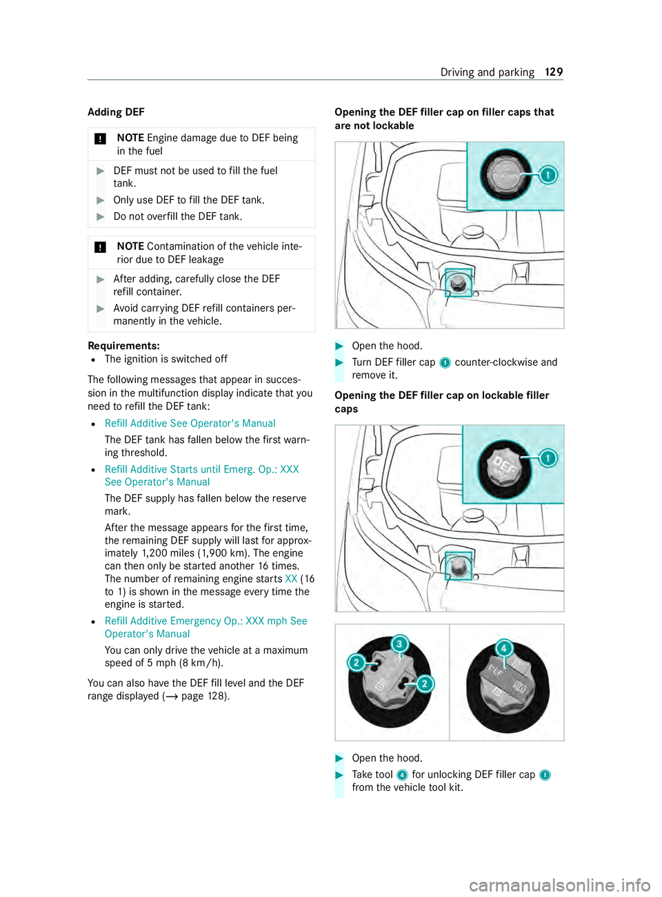
the DEF filler cap on filler caps that
are not loc kable #
Open the hood. #
Turn DEF filler cap 1coun ter-clockwise and
re mo veit.
Opening the DEF filler cap on loc kable filler
caps #
Open the hood. #
Take tool 4 for unlocking DEF filler cap 1
from theve hicle tool kit. Driving and parking
12 9
Page 154 of 354
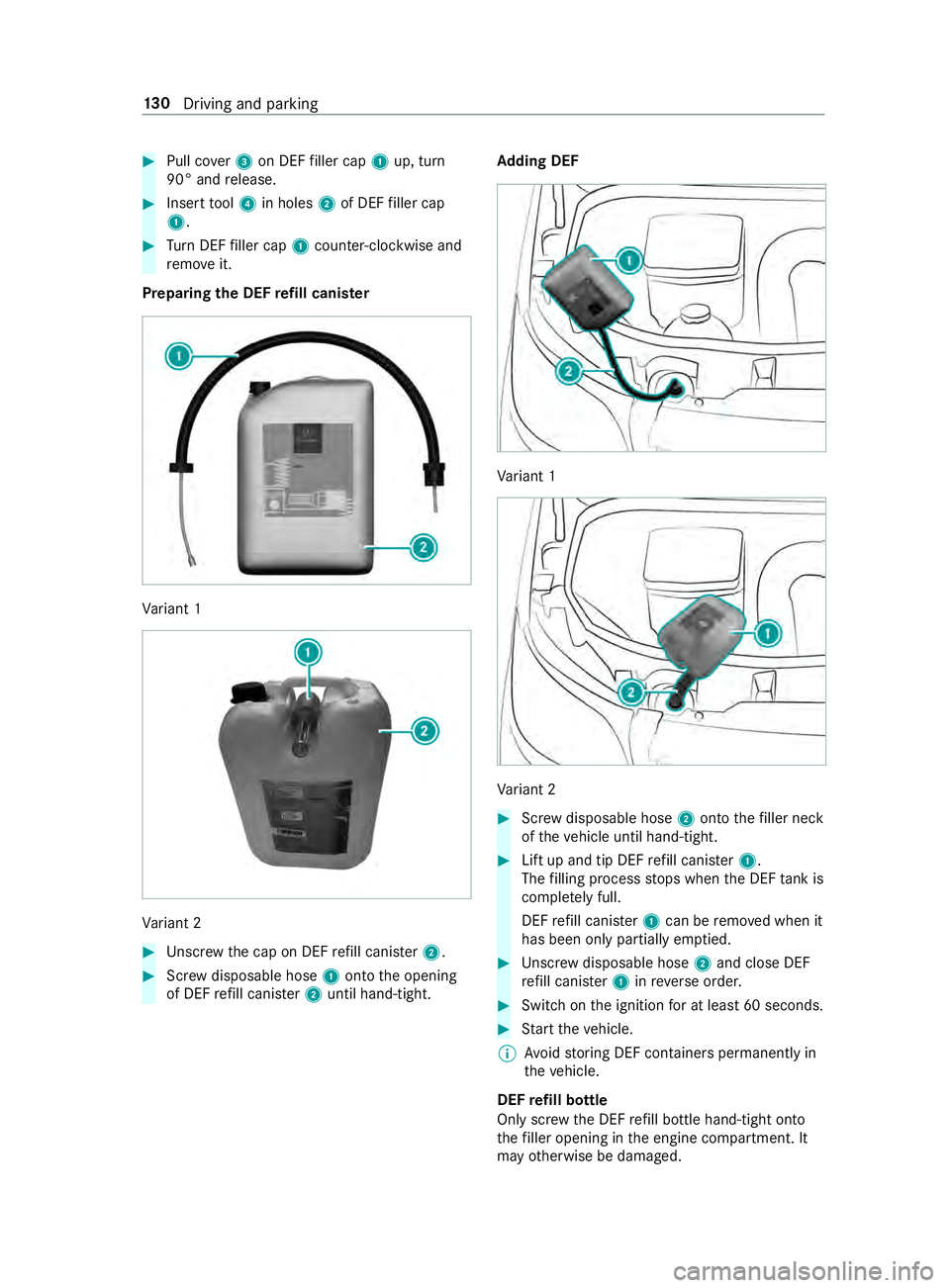
#
Pull co ver3 on DEF filler cap 1up, turn
90° and release. #
Insert tool 4 in holes 2of DEF filler cap
1. #
Turn DEF filler cap 1coun ter-clockwise and
re mo veit.
Preparing the DEF refill canis ter Va
riant 1 Va
riant 2 #
Unscr ewthe cap on DEF refill canis ter2. #
Screw disposable hose 1onto the opening
of DEF refill canis ter2 until hand-tight. Ad
ding DEF Va
riant 1 Va
riant 2 #
Screw disposable hose 2onto thefiller neck
of theve hicle until hand-tight. #
Lift up and tip DEF refill canis ter1.
The filling process stops when the DEF tank is
comple tely full.
DEF refill canis ter1 can be remo ved when it
has been only partially em ptied. #
Unscr ewdisposable hose 2and close DEF
re fill canis ter1 inreve rse order. #
Switch on the ignition for at least 60 seconds. #
Start theve hicle.
% Av
oid storing DEF containers permanent lyin
th eve hicle.
DEF refill bottle
Only scr ewthe DEF refill bottle hand-tight onto
th efiller opening in the engine compartment. It
may otherwise be damaged. 13 0
Driving and pa rking
Page 155 of 354
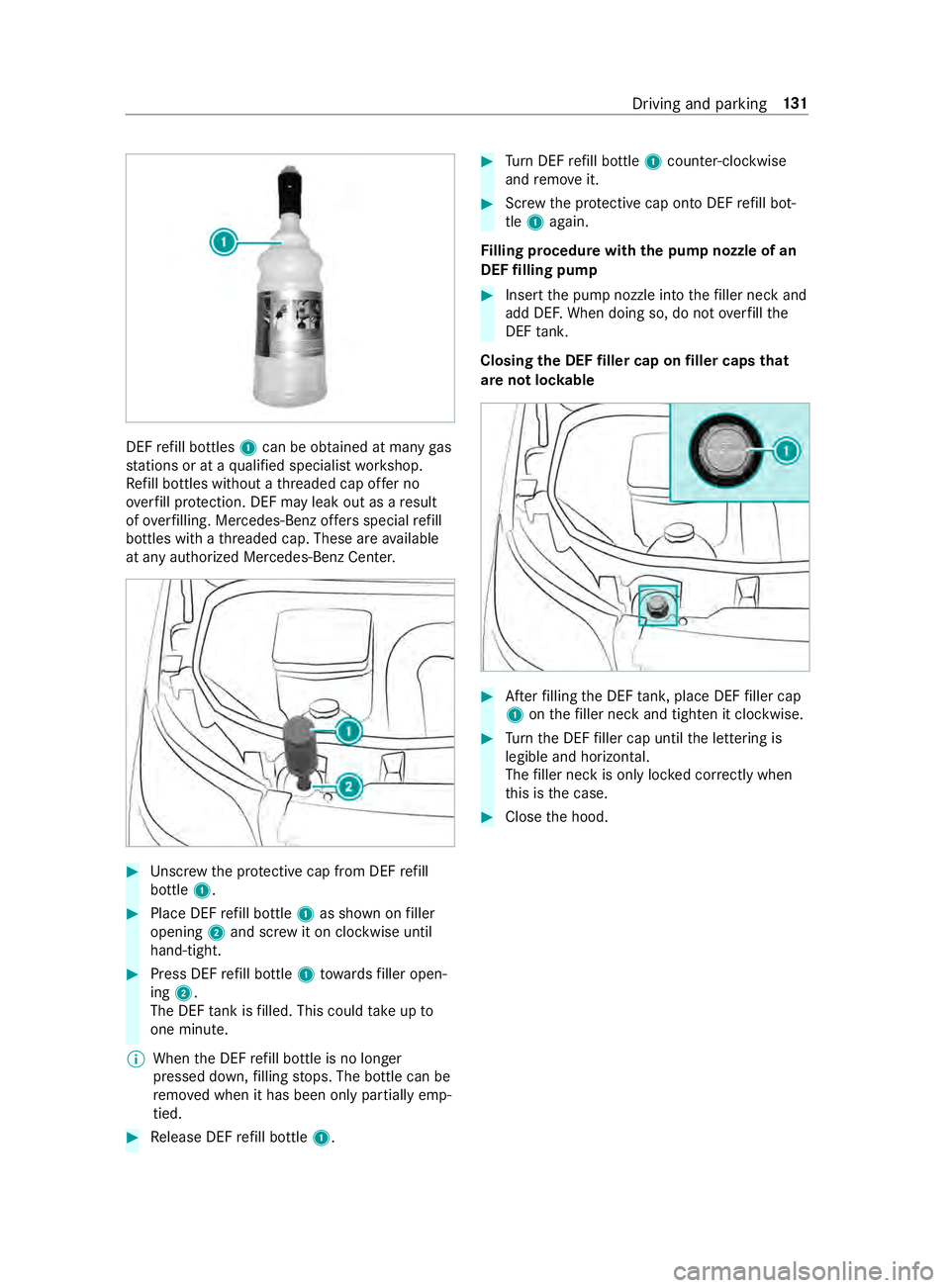
DEF
refill bottles 1can be obtained at many gas
st ations or at a qualified specialist workshop.
Re fill bottles without a thre aded cap of fer no
ove rfill pr otection. DEF may leak out as a result
of ove rfilling. Mercedes-Benz of fers special refill
bottles with a thre aded cap. These are available
at any authorized Mercedes-Benz Center. #
Unscr ewthe pr otective cap from DEF refill
bottle 1. #
Place DEF refill bottle 1as shown on filler
opening 2and scr ewit on clockwise until
hand-tight. #
Press DEF refill bottle 1towa rdsfiller open‐
ing 2.
The DEF tank is filled. This could take up to
one minute.
% When
the DEF refill bottle is no longer
pressed down, filling stops. The bottle can be
re mo ved when it has been only partially emp‐
tied. #
Release DEF refill bottle 1. #
Turn DEF refill bottle 1coun ter-clockwise
and remo veit. #
Screw the pr otective cap onto DEF refill bot‐
tle 1 again.
Fi lling procedure with the pu mpnozzle of an
DEF filling pump #
Insert the pump nozzle into thefiller neck and
add DE F.When doing so, do not overfill the
DEF tank.
Closing the DEF filler cap on filler caps that
are not loc kable #
Afterfilling the DEF tank, place DEF filler cap
1 onthefiller neck and tigh ten it clo ckwise. #
Turn the DEF filler cap until the lettering is
legible and horizontal.
The filler neck is only loc ked cor rectly when
th is is the case. #
Close the hood. Driving and parking
131
Page 189 of 354
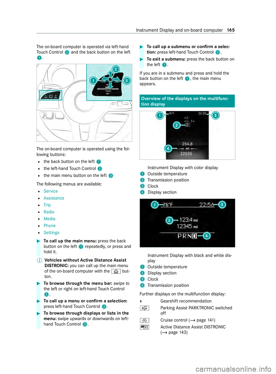
The on-board computer is operated via left-hand
To uch Control 2and the back button on the left
1. The on-board computer is operated using
thefo l‐
lowing buttons:
R the back button on the left 1
R the left-hand Touch Control 2
R the main menu button on the left 3
The following menus are available:
R Service
R Assistance
R Trip
R Radio
R Media
R Phone
R Settings #
Tocall up the main menu: pressthe back
button on the left 1repeatedly, or press and
hold it.
% Ve
hicles without Active Di stance Assist
DISTRO NIC:you can call up the main menu
of the on-board computer with the00E2 but‐
to n. #
Tobrows eth rough the menu bar: swipeto
th e left or right on left-hand Touch Control
2. #
Tocall up a menu or confirm a selection:
press left-hand Touch Control 2. #
Tobrows eth rough displa ysor lists in the
menu: swipe upwards or down wards on left-
hand Touch Control 2. #
Tocall up a submenu or confirm a selec‐
tion: press left-hand Touch Control 2. #
Toexit a submenu: pressthe back button on
th e left 1.
If yo u are in a submenu and press and hold the
back button on the left 1,the main menu
appears. Overview of
the displa yson the multifunc‐
tion display In
stru ment Display with color display
1 Outside temp erature
2 Transmission position
3 Clock
4 Display section In
stru ment Display with black and white dis‐
play
1 Outside temp erature
2 Display section
3 Clock
4 Transmission position
Fu rther displa yson the multifunction display:
0097 Gearshift
recommendation
é Parking Assist PARKTRONIC swit ched
off
00B2 Cruise cont
rol (/ page 141)
ç Active Dis tance Assi stDISTRONIC
(/ page 143) In
stru ment Display and on-board computer 16 5