ESP MITSUBISHI 3000GT 1991 Repair Manual
[x] Cancel search | Manufacturer: MITSUBISHI, Model Year: 1991, Model line: 3000GT, Model: MITSUBISHI 3000GT 1991Pages: 1146, PDF Size: 76.68 MB
Page 1082 of 1146
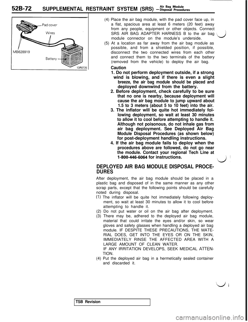
52B-72SUPPLEMENTAL RESTRAINT SYSTEM (SRS) - &%~~~~~ures(4) Place the air bag module, with the pad cover face up, in
a flat, spacious area at least 6 meters (20 feet) away
from any people, equipment or other objects. Connect
SRS AIR BAG ADAPTER HARNESS B to the air bag
mdmodule connector on the module’s underside.
(5) At a location as far away from the air bag module as
possible, and from a shielded position, if possible,
disconnect the two connected wires from each other
and connect them to the two terminals of the battery
(removed from the vehicle) to deploy the air bag.
Caution1. Do not perform deployment outside, if a strong
wind is blowing, and if there is even a slight
breeze, the air bag module should be placed anddeployed downwind from the battery.
2. Before deployment, check carefully to be sure
that no one is nearby, because deployment will
cause the air bag module to jump upward about
1.5 to 3 meters (about 5 to 10 feet) into the air.3. The inflator will be quite hot immediately fol-
lowing deployment, so wait at least 30 minutes
to allow it to cool before attempting to handle it.
Although not poisonous, do not inhale gas fromair bag deployment. See Deployed Air Bag
Module Disposal Procedures (as shown below)for post-deployment handling instructions.
4. If the air bag module fails to deploy when the
procedures above are followed, do not go near
the module. Contact your regional Tech Line at
l-800-446-6064 for instructions.\J’
DEPLOYED AIR BAG MODULE DISPOSAL PROCE-
DURESAfter deployment, the air bag module should be placed in a
plastic bag and disposed of in the same manner as any other
scrap parts, except that the following points should be carefully
noted during disposal.
(1) The inflator will be quite hot immediately following deploy-
ment, so wait at least 30 minutes to allow it to cool before
attempting to handle it.
(2) Do not put water or oil on the air bag after deployment.
(3) There may be, adhered to the deployed air bag module,
material that could irritate the eyes and/or skin, so wear
gloves and safety glasses when handling a deployed air bag
module. IF DESPITE THESE PRECAUTIONS, THE MATE-
RIAL DOES, GET INTO THE EYES OR ON THE SKIN,
IMMEDIATELY RINSE THE AFFECTED AREA WITH A
LARGE AMOUNT OF CLEAN WATER.
IF ANY IRRITATION DEVELOPS, SEEK MEDICAL
A-I-TEN-TION.
(4) Put the deployed air bag in a hermetically sealed container
and discarded it.
‘LJ i
TSB Revision
Page 1083 of 1146
55-1
HEATER, AIR
CONDITIONER
AND VENTILATION
CONTENTSM55AA- -
HEATERS AND AIR CONDITIONING................3HEATER UNIT*........................................................................22
SPECIFICATIONS
....................................................................3REFRIGERANT LINE................................................................35General Specifications
........................................................3RESISTOR................................................................................20Lubricants
............................................................................4SAFETY PRECAUTIONS........................................................9Sealant and Adhesive............................................................4
Service Specifications3SERVICE ADJUSTMENT PROCEDURES............................10........................................................
SPECIAL TOOLS4Charging Procedures............................................................11
i
........................................................................Charging the Refrigerant....................................................12Compressor Drive Belt Adjustment....................................11
HEATERS AND MANUAL AIR CONDITIONER5Compressor Noise................................................................16
................................................16
AIR CONDITIONER SWITCH................................................21Handling Tubing andFittings
Idle-up Operation Check....................................................17
BELT LOCK CONTROLLER20Performance Test................................................................15....................................................
BLOWER ASSEMBLYPower Relay Check............................................................17............................................................23Refrigerant Leak Repair Procedure....................................15COMPRESSOR........................................................................
27TestProcedures....................................................................10
CONDENSER AND CONDENSER FAN MOTOR................33TROUBLESHOOTING............................................................5
ENGINE COOLANT TEMPERATURE SWITCH....................
39VENTILATORS (AIR INLET AND AIR OUTLET)................38
EVAPORATOR
........................................................................
25VENTILATORS (INSTRUMENT PANEL)*............................36
HEATER CONTROL ASSEMBLY*
........................................18CONTINUED ON NEXT PAGE
SUPPLEMENTAL RESTRAINT SYSTEM (SRS)
(1)A Supplemental Restraint System (SRS), which uses a driver-side air bag, has been installed in the 3000GT.(2)The SRS includes the following components: impact sensors, SRS diagnosis unit: SRS warning light, air bagmodule, clock spring, interconnecting wiring. Other SRS-related components (that may have to be
removed/installed in connection with SRS service or maintenance) are indicated in the table of contents byan asterisk (*).
WARNING!(1)Improper service or maintenance of any component of the SRS, or any SRS-related component, can lead to
personal injury or death to service personnel (from inadvertent firing of the air bag) or to the driver (fromrendering the
SRS inoperative).(2) Service or maintenance of any SRS component or SRS-related component must be performed only at anauthorized MITSUBISHI dealer.
(3) MITSUBISHI dealer personnel must thoroughly review this manual, and especially its GROUP 52B
-Supplemental Restraint System (SRS), before beginning any service or maintenance of any component of theSRS or any SRS-related component.
Page 1091 of 1146
HEATERS AND MANUAL AIR CONDITIONER - safety Pre=utm55-9
SAFETY PRECAUTIONSR-12 refrigerant is a chlorofluoro-carbon
(CFC) that
can contribute to the depletion of the ozone layer in
the upper atmosphere.
Ozone filters out harmful radiation from the sun.
To assist in protecting the ozone layer, Mitsubishi
Motor Sales of America recommends that a R-12
refrigerant recycling device that meets SAE stan-
dard
J1991 be used.
Contact an automotive service equipment supplier
for refrigerant recycling equipment that is available
in your area.
The refrigerant used in all air conditioner is R-l 2. It is
transparent and colorless in both the liquid and
vapor state. Since it has a boiling point of
-29.8”C(-21.7”F), at atmospheric pressure, it will be a vapor
at all normal temperatures and pressures. The vapor
is heavier than air, non-flammable, and nonexplo-
sive. It is nonpoisonous except when it is in direct
contact with open flame. It is noncorrosive except
when combined with water. The following precau-
tions must be observed when handling R-12.
CautionWear safety goggles when servicing the refri-
geration system.R-12 evaporates so rapidly at normal atmospheric
pressures and temperatures that it tends to freeze
anything it contacts. For this reason, extreme care
must be taken to prevent any liquid refrigerant from
contacting the skin and especially the eyes. Always
wear safety goggles when servicing the refrigera-
tion part of the air conditioning system. Keep a
bottle of sterile mineral oil handy when working on
the refrigeration system. Should any liquid re-
frigerant get into the eyes, use a few drops of
mineral oil to wash them out. R-12 is rapidly
absorbed by the oil. Next splash the eyes with
plenty of cold water. Call your doctor immediately
even though irritation has ceased after treatment.
CautionDo not heat R-12 above 52°C
(125.6”F).
M55PAAFIn most instances, moderate heat is required to
bring the pressure of the refrigerant in its container
above the pressure of the system when charging or
adding refrigerant. A bucket or large pan of hot
water not over 52°C
(125.6”F) is all the heat required
for this purpose. Do not heat the refrigerant contain-
er with a blow torch or any other means that would
raise temperature and pressure above this tempera-
ture. Do not weld or steam clean on or near the
system components or refrigerant lines.
Caution
Keep R-12 containers upright when charging the
system.When metering R-12 into the refrigeration system,
keep the supply tank or cans in an upright position. If
the refrigerant container is on its side or upside
down, liquid refrigerant will enter the system and
damage the compressor.
CautionAlways work in a well-ventilated room.
Good ventilation is vital in the working area.
Although R-12 vapor is normally nonpoisonous,
contact with an open flame can cause the vapor to
become very poisonous. A poisonous gas is pro-
duced when using the flame-type leak detector.
Avoid inhaling the fumes from the leak detector.
CautionDo not allow liquid refrigerant to touch bright
metal.Refrigerant will tarnish bright metal and chrome
surfaces, and in combination with moisture can
severely corrode all metal surfaces.
1 TSB Revision
Page 1093 of 1146
HEATERS AND MANUAL AIR CONDITIONER -Service Adjustment Procedures 55 1 1
lr In et sensor
UC03xD:c.-;am$2lYXSC0x.x
xa0:: :,:::25 cc,ii 77h>Temperature20A043F
argqse
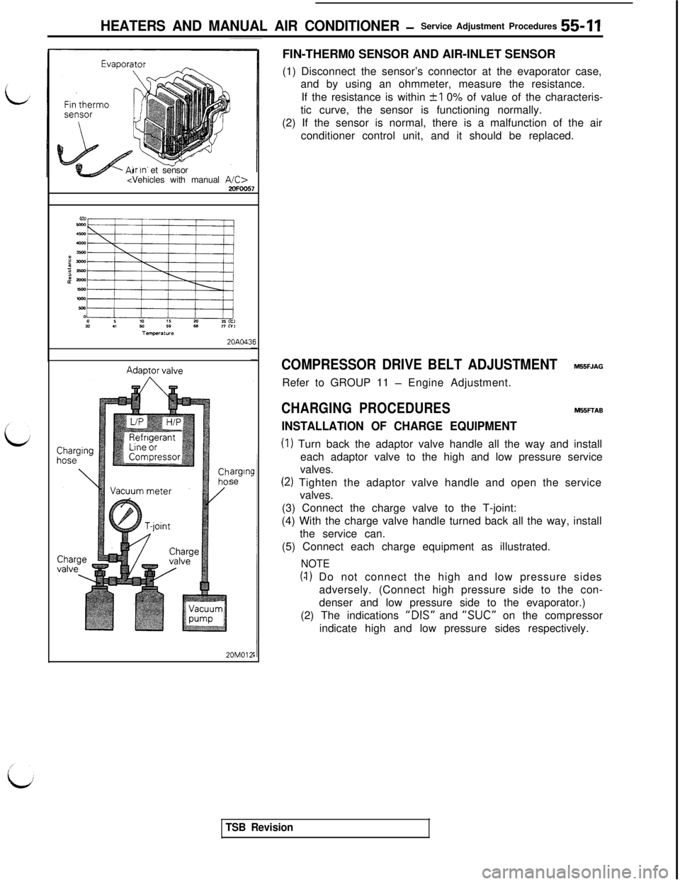
20M012FIN-THERM0 SENSOR AND AIR-INLET SENSOR
(1) Disconnect the sensor’s connector at the evaporator case,
and by using an ohmmeter, measure the resistance.
If the resistance is within
+I 0% of value of the characteris-
tic curve, the sensor is functioning normally.
(2) If the sensor is normal, there is a malfunction of the air
conditioner control unit, and it should be replaced.
COMPRESSOR DRIVE BELT ADJUSTMENTM55FJAGRefer to GROUP 11
- Engine Adjustment.
CHARGING PROCEDURESM55FTAB
INSTALLATION OF CHARGE EQUIPMENT
(I) Turn back the adaptor valve handle all the way and install
each adaptor valve to the high and low pressure service
valves.
(2) Tighten the adaptor valve handle and open the service
valves.
(3) Connect the charge valve to the T-joint:
(4) With the charge valve handle turned back all the way, install
the service can.
(5) Connect each charge equipment as illustrated.
NOTE
(4) Do not connect the high and low pressure sides
adversely. (Connect high pressure side to the con-
denser and low pressure side to the evaporator.)
(2) The indications
“DIS” and “SUC” on the compressor
indicate high and low pressure sides respectively.
TSB Revision
Page 1098 of 1146
55-16 HEATERS AND MANUAL AIR CONDITIONER -Service Adjustment Procedures
LOW CHARGE~
If the system has not lost all of its refrigerant charge; locate and
repair all leaks. If it is necessary to increase the system
pressure to find the leak (because of an especially low charge)
‘iaadd of refrigerant. If it is oossible to reoair the leak without
discharging-the refrigerant system, use the procedure for
correcting low refrigerant level.
HANDLING TUBING AND FITTINGSM55FlAFKinks in the refrigerant tubing or sharp bends in the refrigerant
hose lines will greatly reduce the capacity of the entire system.
High pressures are produced in the system when it is
operating. Extreme care must be exercised to make sure that
all connections are pressure tight. Dirt and moisture can enter
the system when it is opened for repair or replacement of lines
or components. The following precautions must be observed.
The system must be completely discharged before opening
any fitting of connection in the refrigeration system. Open
fittings with caution even after the system has been dis-
charged. If any pressure is noticed as a fitting is loosened, allow
trapped pressure to bleed off very slowly.
Never attempt to rebend formed lines to fit. Use the correct
line for the installation you are servicing.
A good rule for the flexible hose lines is keep the radius of all
bends at least 10 times the diameter of the hose.
Sharper bends will reduce the flow of refrigerant. The flexible
hose lines should be routed so that they are at least 80 mm (3
in.) from the exhaust manifold. It is good practice to inspect all
flexible hose lines at least once a year to make sure they are in
good condition and properly routed.
\ Aj iUnified plumbing connections with O-rings. These O-rings are
-not reusable.
I
COMPRESSOR NOISEM55FlAD
When investigating an air conditioning related noise, you must
first know the conditions when the noise occurs. These
conditions are: weather, vehicle speed, in gear on neutral,
engine temperature or any other special conditions.
Noises that develop during air conditioning operation can often
be misleading. For example: what sounds like a failed front
bearing or connecting rod. may be caused by loose bolts, nuts,
mounting brackets, or a loose clutch assembly. Verify acces-
sory drive belt tension (power steering or alternator).
Improper accessory drive belt tension can cause a misleading
noise when the compressor is engaged and little or no noise
when the compressor is disengaged.
Drive belts are speed sensitive. That is, at different engine
speeds, and depending upon belt tension, belts can develop
unusual noises that are often mistaken for mechanical prob-
lems within the compressor.
TSB Revision
Page 1136 of 1146
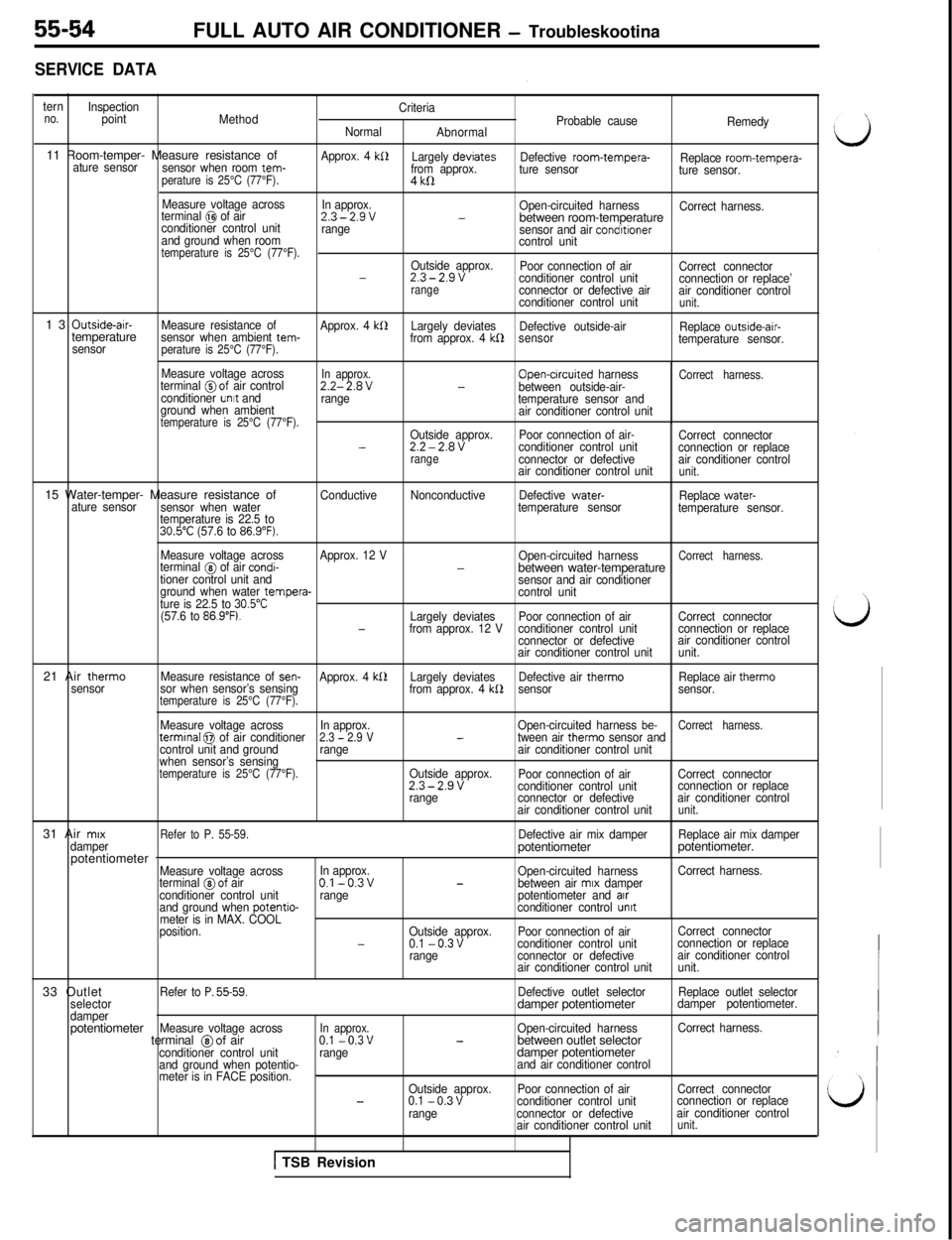
SERVICE DATA
ternno.Inspection
point
MethodCriteria
Probable cause
Normal
AbnormalRemedy11 Room-temper- Measure resistance of
sensor when room tem- ature sensorperature is 25°C (77°F).
Approx. 4 kS1Largely devrates
from approx.Defective room-tempera-
Replace room-tempera-
ture sensor
ture sensor.4
kll
Measure voltage across
In approx.
terminal @I of airOpen-circuited harness
Correct harness.2.3-2.9v-conditioner control unitbetween room-temperaturerange
sensor and air condrtionerand ground when room
control unittemperature is 25°C (77°F).Outside approx.
Poor connection of air
Correct connector-2.3-2.9vconditioner control unit
connection or replace’rangeconnector or defective air
air conditioner control
conditioner control unitunit.13
Outside-air-
Measure resistance of
Approx. 4 kllLargely deviates
Defective outside-air
Replace outside-air-temperaturesensor when ambient tem-
from approx. 4 kf2sensor
temperature sensor.
sensorperature is 25°C (77°F).
Measure voltage acrossIn approx.terminal @of air controlOpen-crrcuited harnessCorrect harness.2.2-2.8V-between outside-air-
conditioner unrt and
range
temperature sensor and
ground when ambient
air conditioner control unit
temperature is 25°C (77°F).Outside approx.Poor connection of air-
Correct connector-2.2-2.8Vconditioner control unit
connection or replacerangeconnector or defectiveair conditioner control
air conditioner control unitunit.15 Water-temper- Measure resistance of
ConductiveNonconductiveDefective water-
Replace water-
ature sensor
sensor when watertemperature sensor
temperature sensor.
temperature is 22.5 to
30.5”C (57.6 to 86.9”F).21 Air therm0
sensorMeasure voltage acrossApprox. 12 V
Open-circuited harness
Correct harness.terminal @ of air condi--between water-temperaturetioner control unit and
sensor and air conditioner
ground when water tempera-
control unit
ture is 22.5 to 30.5”C(57.6 to 86.9”F).Largely deviatesPoor connection of airCorrect connector-from approx. 12 Vconditioner control unitconnection or replace
connector or defectiveair conditioner control
air conditioner control unitunit.
Measure resistance of
sen-Approx. 4 kS2Largely deviatesDefective air therm0Replace air therm0
sor when sensor’s sensing
from approx. 4 kb2sensorsensor.temperature is 25°C (77°F).
Measure voltage acrossIn approx.Open-circuited harness be-Correct harness.termrnal 0 of air conditioner2.3 - 2.9 V-tween air therm0 sensor and
control unit and groundrangeair conditioner control unit
when sensor’s sensing
temperature is 25°C (77°F).Outside approx.
Poor connection of airCorrect connector2.3-2.9vconditioner control unitconnection or replace
rangeconnector or defectiveair conditioner control
air conditioner control unit
unit.31 Air
mrx
Refer to P. 55-59.Defective air mix damperReplace air mix damper
damperpotentiometerpotentiometer.
potentiometer
-Measure voltage acrossIn approx.
Open-circuited harnessCorrect harness.
terminal @of airO.l-0.3v-between air mrx damper
conditioner control unitrangepotentiometer and arrand ground when potentio-conditioner control unrtmeter is in MAX. COOL
position.Outside approx.Poor connection of airCorrect connector
-0.1 -0.3vconditioner control unitconnection or replace
rangeconnector or defectiveair conditioner control
air conditioner control unitunit.33 Outlet
Refer to P. 55-59.Defective outlet selectorReplace outlet selector
selectordamper potentiometerdamper potentiometer.
damperpotentiometer
Measure voltage acrossIn approx.Open-circuited harnessCorrect harness.terminal @of air0.1 -0.3v-between outlet selectorconditioner control unitrangedamper potentiometerand ground when potentio-and air conditioner control
meter is in FACE position._Outside approx.Poor connection of airCorrect connector-0.1 -0.3vconditioner control unitconnection or replace
rangeconnector or defectiveair conditioner control
air conditioner control unit
unit.FULL AUTO AIR CONDITIONER
- Troubleskootina
1 TSB Revision
Page 1143 of 1146

FULL AUTO AIR CONDITIONER - Sensors55-615. REMOVAL OF PHOTO SENSOR
Using a trim stick, remove the photo sensor from the
defroster garnishes.
Thermometer
2OAO19:
c
3
INSPECTIONM55OcALl
WATER TEMPERATURE SENSOR
(1) Dip the water-temperature sensor in hot water and, using astove, etc., raise the water temperature.
(2) Check that the water-temperature sensor is conductive
when the water temperature reaches the specified temper-
ature.Standard value: 26.5 + 4°C (79.7
+ 7.2”Fl
OUTSIDE-AIR-TEMPERATURE SENSOR
The condition can be considered normal if the resistances are
measured within the ranges of 3.98
- 4.12 kilohms and 2.21 -
2.35 kilohms, respectively, when the outside-air-temperature
sensor is submerged in warm water of 25°C (77°F) and 40°C(104°F) for one minute or longer each.
NOTE
The relationship between the outside-air-temperature and theresistance values is as shown below.
&$$nt temperatureI-10 /0110 / i01 25/ 301 40 /(14) (32) (50) (68) (77) (86) (104)
Resistance value(reference) k0
1 TSB Revision