roof rack MITSUBISHI 3000GT 1991 Service Manual
[x] Cancel search | Manufacturer: MITSUBISHI, Model Year: 1991, Model line: 3000GT, Model: MITSUBISHI 3000GT 1991Pages: 1146, PDF Size: 76.68 MB
Page 48 of 1146
00-44
GENERAL - Main Sealant and Adhesive Table
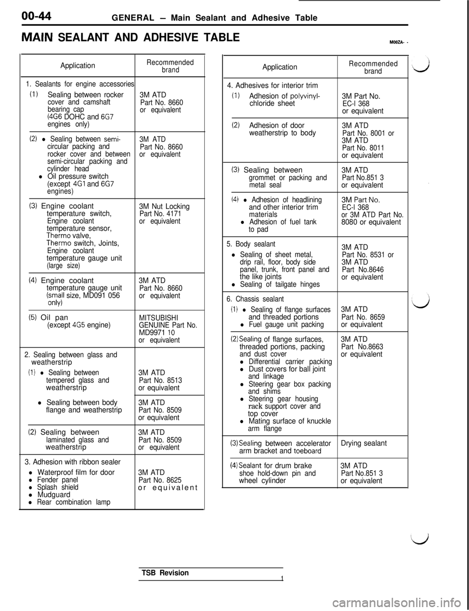
MAIN SEALANT AND ADHESIVE TABLEMWZA- -
ApplicationRecommendedbrand
1. Sealants for engine accessories
(I 1Sealing between rocker
3M ATDcover and camshaft
Part No. 8660
bearing cap
(4G6 DOHC and 6G7or equivalent
engines only)
(2) l Sealing between semi-3M ATD
circular packing and
Part No. 8660
rocker cover and between
semi-circular packing andor equivalent
cylinder head
l Oil pressure switch
(except 4Gl and 6G7engines)
(3) Engine coolanttemperature switch,Engine coolanttemperature sensor,Therm0 valve,Therm0 switch, Joints,Engine coolanttemperature gauge unit(large size)
3M Nut LockingPart No. 4171
or equivalent
(4) Engine coolanttemperature gauge unit(;.s;il size, MD091 0563M ATDPart No. 8660
or equivalent
(5) Oil pan(except 4G5 engine)MITSUBISHI
GENUINE Part No.
MD9971 10or equivalent
2. Sealing between glass and
weatherstrip
(I 1 l Sealing between
tempered glass and
weatherstrip
l Sealing between body
flange and weatherstrip3M ATD
Part No. 8513or equivalent
3M ATD
Part No. 8509or equivalent
(2) Sealing betweenlaminated glass andweatherstrip
3. Adhesion with ribbon sealer
l Waterproof film for doorl Fender panell Splash shieldl Mudguardl Rear combination lamp
3M ATDPart No. 8509
or equivalent
3M ATDPart No. 8625or equivalent
ApplicationRecommended
brand
4. Adhesives for interior trim
(1)Adhesion of polyvinyl-chloride sheet3M Part No.EC-l 368or equivalent
(2)Adhesion of door
3M ATD
weatherstrip to body
Part No. 8001 or3M ATDPart No. 8011or equivalent
(3) Sealing betweengrommet or packing and
metal seal
(4) l Adhesion of headliningand other interior trimmaterialsl Adhesion of fuel tank
to pad
3M ATDPart No.851 3or equivalent3M
Part-No.
EC-l 368
or 3M ATD Part No.
8080 or equivalent
5. Body sealant3M ATDl Sealing of sheet metal,
Part No. 8531 or
drip rail, floor, body side3M ATDpanel, trunk, front panel and
Part No.8646the like jointsl Sealing of tailgate hingesor equivalent
6. Chassis sealant
(I 1 l Sealing of flange surfaces3M ATD
and threaded portions
Part No. 8659l Fuel gauge unit packingor equivalent
(2)Sealing of flange surfaces,3M ATD
threaded portions, packingPart No.8663
and dust cover
l Differential carrier packingor equivalent
l Dust covers for ball jointand linkage
l Steering gear box packing
and shims
l Steering gear housingrack support cover andtop coverl Mating surface of knucklearm flange
(3)Sealing between accelerator
arm bracket and toeboardDrying sealant
(4)Sealant for drum brakeshoe hold-down pin andwheel cylinder3M ATDPart No.851 3or equivalent
TSB Revision1
Page 877 of 1146
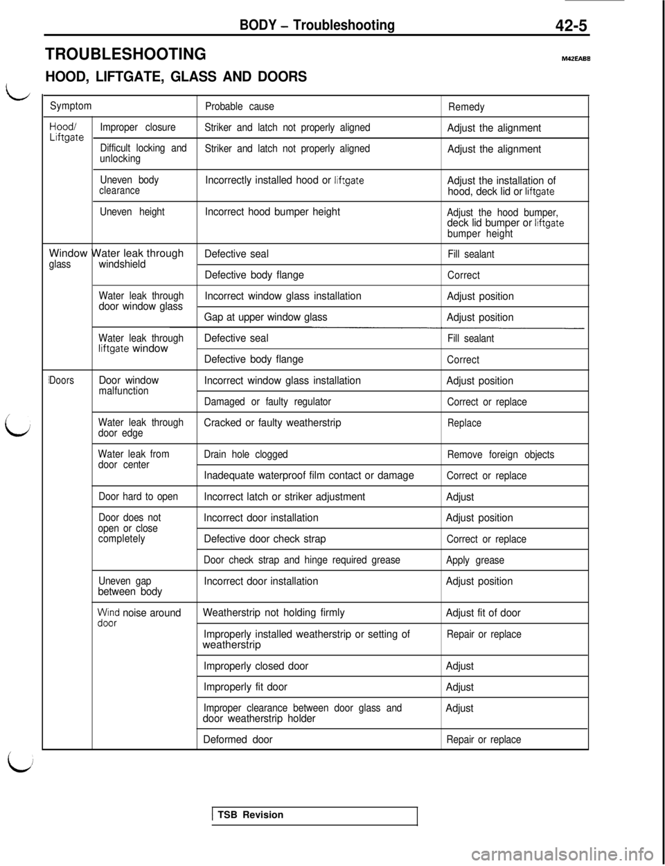
TROUBLESHOOTING
BODY - Troubleshooting42-5
M42EABE
HOOD, LIFTGATE, GLASS AND DOORS
LSymptom
Probable cause
Remedy
Hood/
Improper closureLiftgateStriker and latch not properly alignedAdjust the alignment
Difficult locking and
unlockingStriker and latch not properly alignedAdjust the alignment
Uneven bodyclearanceIncorrectly installed hood or liftgateAdjust the installation of
hood, deck lid or liftgate
Uneven height
Incorrect hood bumper heightAdjust the hood bumper,deck lid bumper or liftgate
bumper heightWindow Water leak through
Defective sealFill sealant
glasswindshield
Defective body flange
Correct
Water leak through
door window glassIncorrect window glass installation
Adjust position
Gap at upper window glass
Adjust position
Water leak throughDefective sealFill sealantliftgate windowDefective body flangeCorrect
DoorsDoor windowmalfunctionIncorrect window glass installation
Adjust position
Damaged or faulty regulator
Correct or replace
Water leak through
Cracked or faulty weatherstripdoor edgeReplace
Water leak from
door centerDrain hole clogged
Remove foreign objects
Inadequate waterproof film contact or damageCorrect or replace
Door hard to open
Incorrect latch or striker adjustment
Adjust
Door does notIncorrect door installationopen or closeAdjust position
completelyDefective door check strapCorrect or replace
Door check strap and hinge required grease
Apply grease
Uneven gap
Incorrect door installation
between bodyAdjust position
yoi$ noise aroundWeatherstrip not holding firmly
Adjust fit of door
Improperly installed weatherstrip or setting of
Repair or replaceweatherstrip
Improperly closed door
Improperly fit door
Improper clearance between door glass anddoor weatherstrip holder
Deformed doorAdjust
Adjust
Adjust
Repair or replace
1 TSB Revision
Page 886 of 1146
42-14BODY - Service Rdiustment ProceduresMB990834-0118A0381
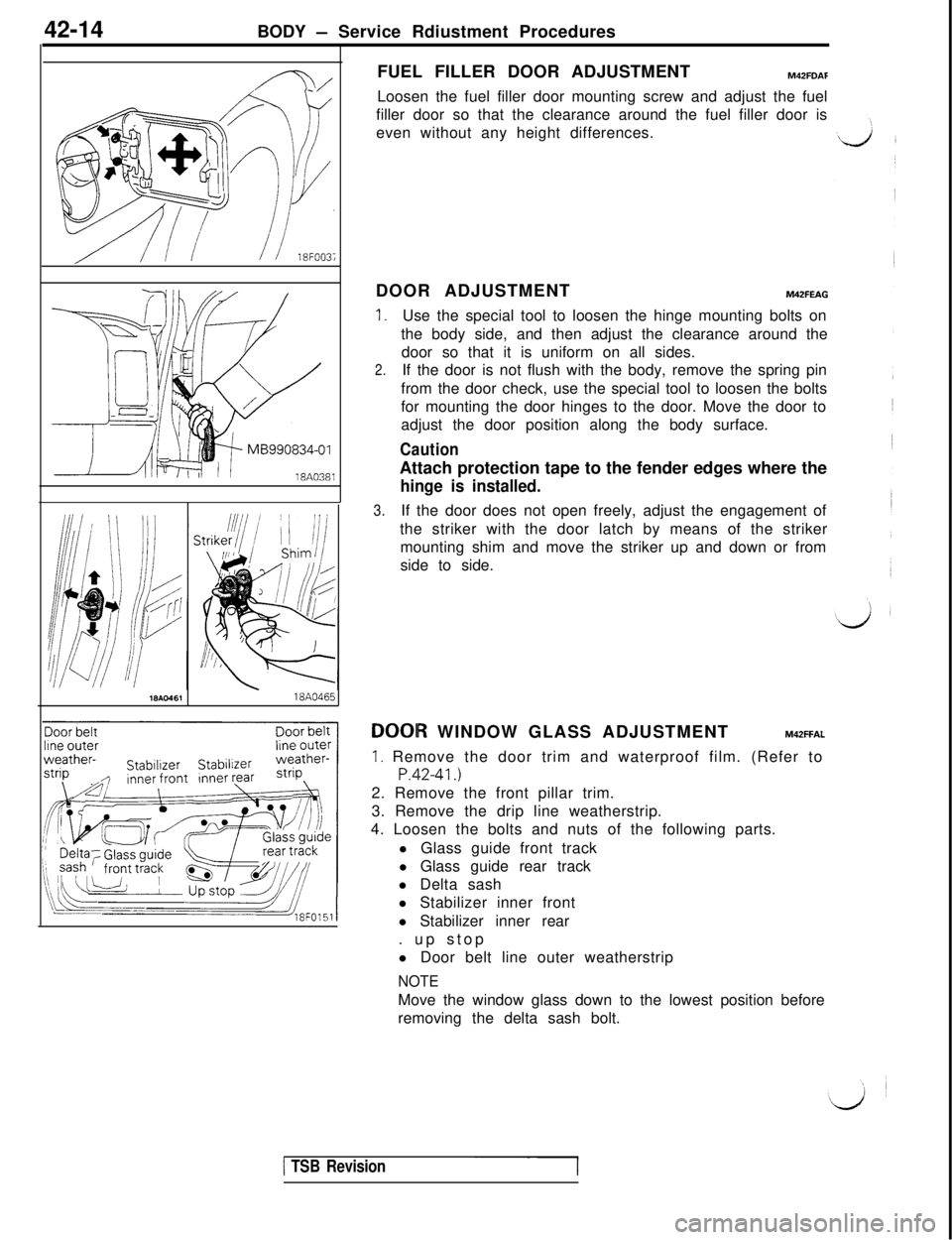
18Ac-46118A0465FUEL FILLER DOOR ADJUSTMENT
M42FDAFLoosen the fuel filler door mounting screw and adjust the fuel
filler door so that the clearance around the fuel filler door is
even without any height differences.
DOOR ADJUSTMENT
M42FEAG
1.Use the special tool to loosen the hinge mounting bolts on
the body side, and then adjust the clearance around the
door so that it is uniform on all sides.
2.If the door is not flush with the body, remove the spring pin
from the door check, use the special tool to loosen the bolts
for mounting the door hinges to the door. Move the door to
adjust the door position along the body surface.
CautionAttach protection tape to the fender edges where the
hinge is installed.
3.If the door does not open freely, adjust the engagement of
the striker with the door latch by means of the striker
mounting shim and move the striker up and down or from
side to side.DOOIR WINDOW GLASS ADJUSTMENT
M42FFAL
1. Remove the door trim and waterproof film. (Refer to
P.42-41.)2. Remove the front pillar trim.
3. Remove the drip line weatherstrip.
4. Loosen the bolts and nuts of the following parts.
l Glass guide front track
l Glass guide rear track
l Delta sash
l Stabilizer inner front
l Stabilizer inner rear
. up stop
l Door belt line outer weatherstrip
NOTEMove the window glass down to the lowest position before
removing the delta sash bolt.
1 TSB Revision-1
Page 888 of 1146
42-16
BODY - Service Adjustment Procedures
StabtlizerInner front18FO15:
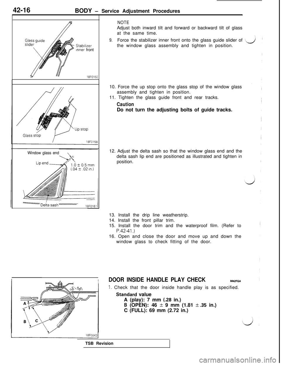
Window glass end
NOTEAdjust both inward tilt and forward or backward tilt of glass
at the same time.
9.Force the stabilizer inner front onto the glass guide slider of
the window glass assembly and tighten in position.
10. Force the up stop onto the glass stop of the window glass
assembly and tighten in position.
11. Tighten the glass guide front and rear tracks.
CautionDo not turn the adjusting bolts of guide tracks.
12. Adjust the delta sash so that the window glass end and the
delta sash lip end are positioned as illustrated and tighten in
position.
13. Install the drip line weatherstrip.
14. Install the front pillar trim.
15. Install the door trim and the waterproof film. (Refer to
P.42-41.)16. Open and close the door and move up and down the
window glass to check fitting of the door.
1DOOR INSIDE HANDLE PLAY CHECKM42FGA
1. Check that the door inside handle play is as specified.
Staindard value
A (play): 7 mm
(.28 in.)
B (OPEN): 46 & 9 mm (1.81 i .35 in.)
C (FULL): 69 mm (2.72 in.)
TSB Revision
Page 914 of 1146
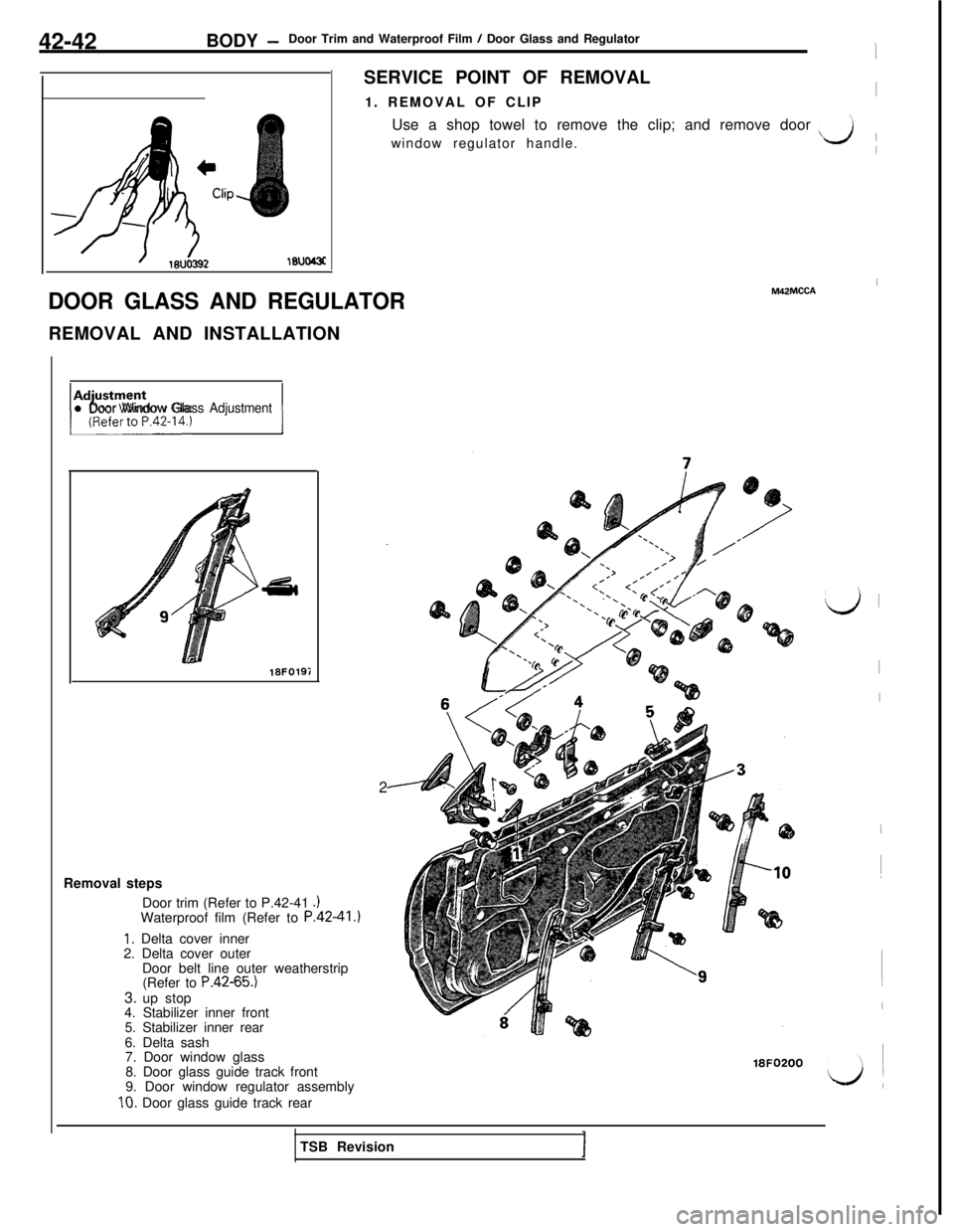
42-42BODY -Door Trim and Waterproof Film / Door Glass and Regulator
ISERVICE POINT OF REMOVAL
1. REMOVAL OF CLIP
IUse a shop towel to remove the clip; and remove door
window regulator handle.
\L.J II
DOOR GLASS AND REGULATORREMOVAL AND INSTALLATION
~;:;zL4., 1l Door Window Glass Adjustment
18FOlQi2
Removal steps
Door trim (Refer to P.42-41
.IWaterproof film (Refer to P.42-41 .I
1. Delta cover inner
2. Delta cover outer
Door belt line outer weatherstrip
(Refer to
P.42-65.)3. up stop
4. Stabilizer inner front
5. Stabilizer inner rear
6. Delta sash
7. Door window glass
8. Door glass guide track front
9. Door window regulator assemblyIO. Door glass guide track rear
IM42MCCA
18FO200
d
I
I
I
!
(
I
L&lTSB Revision
Page 923 of 1146
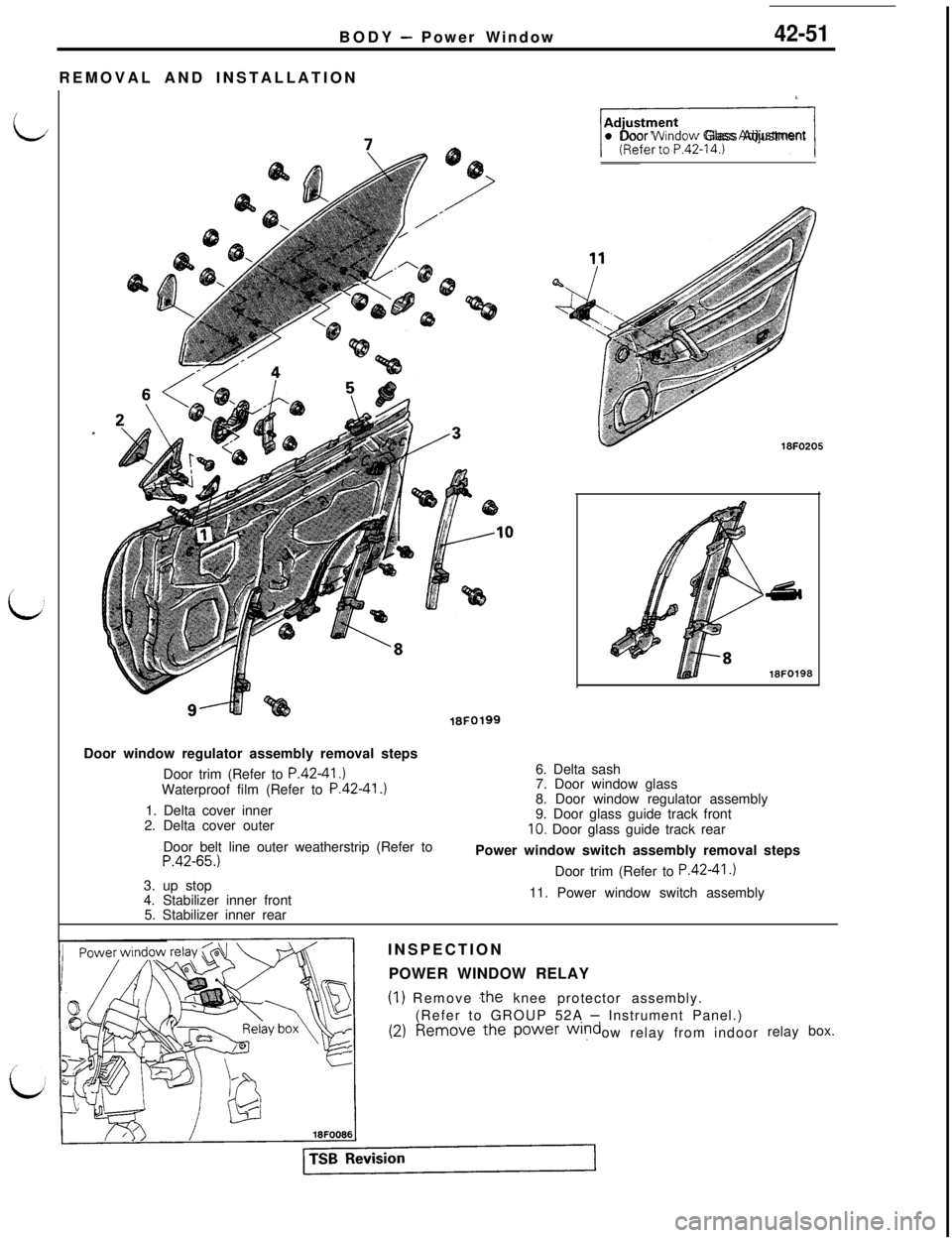
L
/
idBODY
- Power Window
REMOVAL AND INSTALLATION42-51
Cll Door Wlndow Glass Adjustment
18FO205
18FO198Door window regulator assembly removal steps
Door trim (Refer to
P.4241.)Waterproof film (Refer to P.42-41.)1. Delta cover inner
2. Delta cover outer
18FO1996. Delta sash
7. Door window glass
8. Door window regulator assembly
9. Door glass guide track front
10. Door glass guide track rear
Door belt line outer weatherstrip (Refer to
P.42-65.)3. up stop
4. Stabilizer inner frontPower window switch assembly removal steps
Door trim (Refer to P.42-41.)11. Power window switch assembly
5. Stabilizer inner rear
INSPECTION
POWER WINDOW RELAY
(1) Remove .the knee protector assembly.
(Refer to GROUP 52A
- Instrument Panel.)
ow relay from indoorrelaybox.
Page 991 of 1146
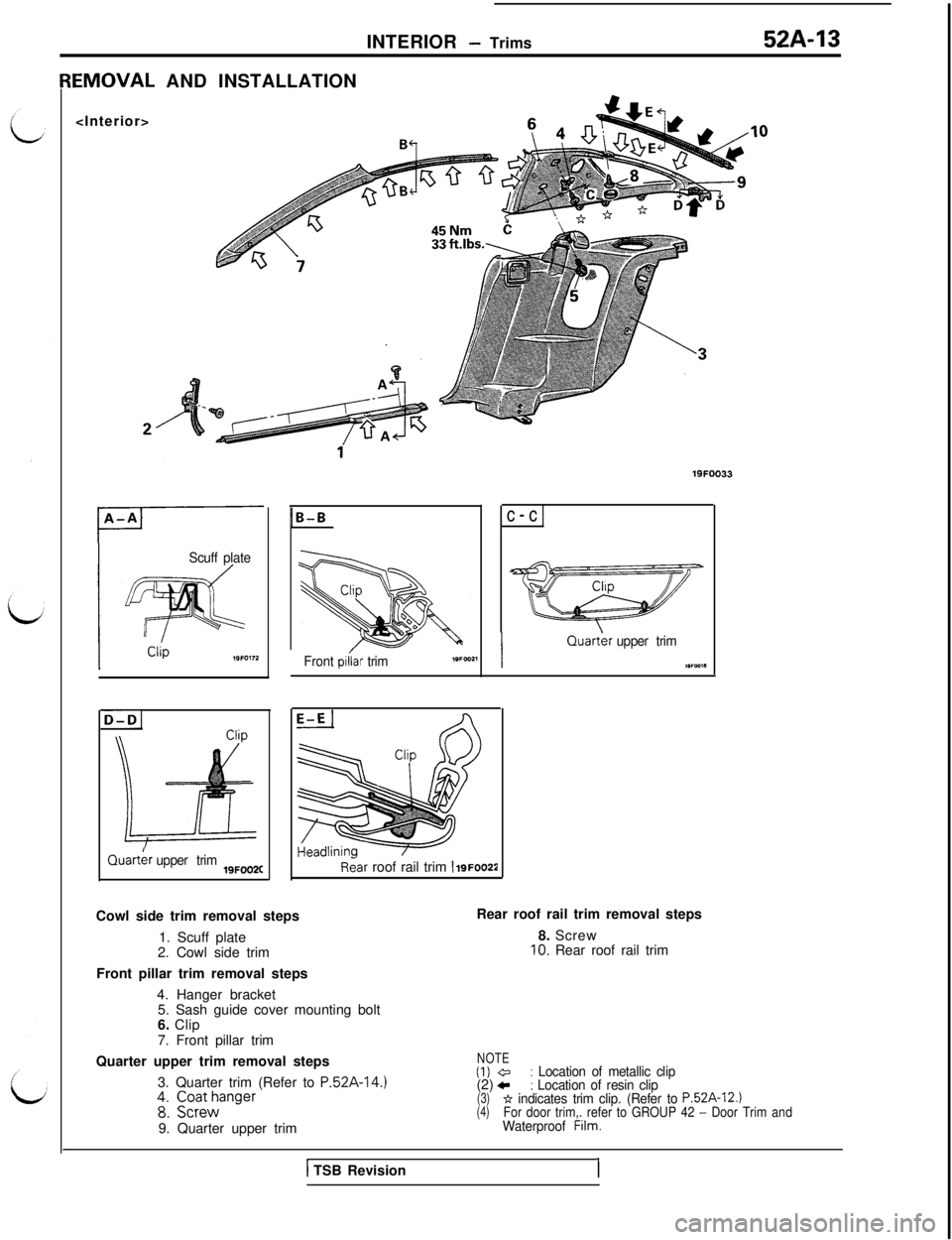
INTERIOR - Trims52A-13EMOVAL AND INSTALLATION
Scuff plate
D-D1Quart&
upper trim19FOO2C
1B-B
Front piiar trimc-cIQuart&
upper trim
,wca*
Rear roof rail trim 1 igFoo22Cowl side trim removal steps
1. Scuff plate
2. Cowl side trim
Front pillar trim removal steps
4. Hanger bracket
5. Sash guide cover mounting bolt
6. Clip
7. Front pillar trimRear roof rail trim removal steps
8. Screw
10. Rear roof rail trim
Quarter upper trim removal steps
3. Quarter trim (Refer to
P.52A-14.)48: ;;;;anger9. Quarter upper trim
1 TSB Revision
NOTE(1) @: Location of metallic clip(2) c: Location of resin clip(3)* indicates trim clip. (Refer to P.52A-12.)(4)For door trim,. refer to GROUP 42 - Door TrimandWaterproof Film.
I
Page 995 of 1146
L
LINTERIOR
- Headlining52A-17
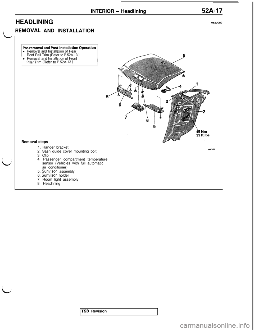
HEADLININGM52lJDBC[EMOVAL AND INSTALLATION
Pre-removal and Post-installation Operationl Removal and Installation of Rear
Roof Rail Trim (Refer to P52A-13.)l Removal and lnstallatron of FrontPillarTrim (Refer to P.52A-13.)Removal steps
1. Hanger bracket
2. Sash guide cover mounting bolt
3. Clip
4. Passenger compartment temperature
sensor (Vehicles with full automatic
air conditioner)
5. Sunvisor assembly
6. Sunvisor holder
7. Room light assembly
8. HeadliningTSB Revision