Ignition circuit MITSUBISHI 380 2005 Workshop Manual
[x] Cancel search | Manufacturer: MITSUBISHI, Model Year: 2005, Model line: 380, Model: MITSUBISHI 380 2005Pages: 1500, PDF Size: 47.87 MB
Page 1381 of 1500

AUTO-CRUISE CONTROL
ENGINE AND EMISSION CONTROL17-50
DTC 1574: Engine ECU and Its Related Components
.
DTC SET CONDITIONS
This DTC is set when there is a failure in the Engine
ECU and its related components.
.
TROUBLESHOOTING HINTS (THE MOST
LIKELY CAUSES FOR THIS CODE TO BE
SET ARE:)
Malfunction of the MPI system.
Malfunction of the A/T system.
Malfunction of the Engine ECU.
Circuit drawings
Refer to circuit diagrams GROUP-90
Refer to configuration diagrams GROUP-80
Refer to component locations GROUP-70
DIAGNOSIS
Required Special Tools:
MB991958: Diagnostic Tool (MUT-III Sub Assembly)
MB991824: V.C.I.
MB991827: MUT-III USB Cable
MB991910: MUT-III Main Harness A
STEP 1. Using Diagnostic Tool MB991958, read the MPI
system diagnostic trouble code.
To prevent damage to Diagnostic Tool MB991958, always
turn the ignition switch to the "LOCK" (OFF) position
before connecting or disconnecting Diagnostic Tool
MB991958.
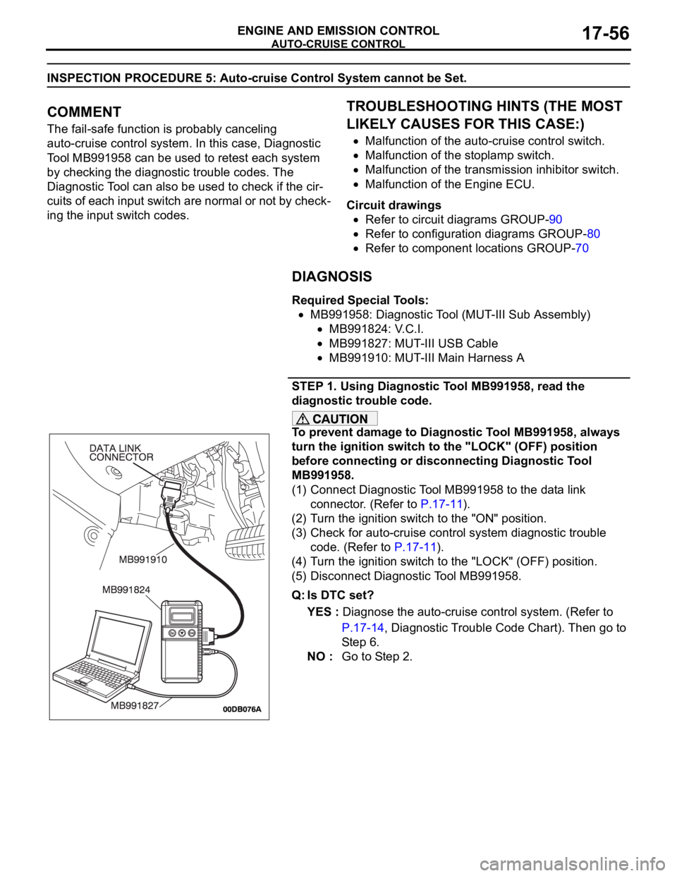
(1) Connect Diagnostic Tool MB991958 to the data link
connector. (Refer to P.17-11).
(2) Turn the ignition switch to the "ON" position.
(3) Check for MPI system diagnostic trouble code. (Refer to
GROUP 13A, MPI Diagnosis
Diagnostic Function How
to Read and Erase Diagnostic Trouble Code 13A-6) .
(4) Turn the ignition switch to the "LOCK" (OFF) position.
(5) Disconnect Diagnostic Tool MB991958.
Q: Is any DTC set?
YES : Diagnose the MPI system. (Refer to GROUP 13A,
MPI Diagnosis
Diagnostic Trouble Code Chart
13A-17) . Then go to Step 4.
NO : Go to Step 2.
Page 1387 of 1500

AUTO-CRUISE CONTROL
ENGINE AND EMISSION CONTROL17-56
INSPECTION PROCEDURE 5: Auto-cruise Control System cannot be Set.
.
COMMENT
The fail-safe function is probably canceling
auto-cruise control system. In this case, Diagnostic
Tool MB991958 can be used to retest each system
by checking the diagnostic trouble codes. The
Diagnostic Tool can also be used to check if the cir-
cuits of each input switch are normal or not by check-
ing the input switch codes.
.
TROUBLESHOOTING HINTS (THE MOST
LIKELY CAUSES FOR THIS CASE:)
Malfunction of the auto-cruise control switch.
Malfunction of the stoplamp switch.
Malfunction of the transmission inhibitor switch.
Malfunction of the Engine ECU.
Circuit drawings
Refer to circuit diagrams GROUP-90
Refer to configuration diagrams GROUP-80
Refer to component locations GROUP-70
DIAGNOSIS
Required Special Tools:
MB991958: Diagnostic Tool (MUT-III Sub Assembly)
MB991824: V.C.I.
MB991827: MUT-III USB Cable
MB991910: MUT-III Main Harness A
STEP 1. Using Diagnostic Tool MB991958, read the
diagnostic trouble code.
To prevent damage to Diagnostic Tool MB991958, always
turn the ignition switch to the "LOCK" (OFF) position
before connecting or disconnecting Diagnostic Tool
MB991958.
(1) Connect Diagnostic Tool MB991958 to the data link
connector. (Refer to P.17-11).
(2) Turn the ignition switch to the "ON" position.
(3) Check for auto-cruise control system diagnostic trouble
code. (Refer to P.17-11).
(4) Turn the ignition switch to the "LOCK" (OFF) position.
(5) Disconnect Diagnostic Tool MB991958.
Q: Is DTC set?
YES : Diagnose the auto-cruise control system. (Refer to
P.17-14, Diagnostic Trouble Code Chart). Then go to
St e p 6 .
NO : Go to Step 2.
Page 1391 of 1500

AUTO-CRUISE CONTROL
ENGINE AND EMISSION CONTROL17-60
INSPECTION PROCEDURE 6: Hunting (Repeated Acceleration and Deceleration) Occurs at the Set
Vehicle Speed.
.
COMMENT
The output shaft speed sensor signal or the throttle
body is suspected.
.
TROUBLESHOOTING HINTS (THE MOST
LIKELY CAUSES FOR THIS CASE:)
Malfunction of the output shaft speed sensor.
Malfunction of the throttle body.
Malfunction of the Engine ECU.
Malfunction of the A/T ECU.
Circuit drawings
Refer to circuit diagrams GROUP-90
Refer to configuration diagrams GROUP-80
Refer to component locations GROUP-70
DIAGNOSIS
Required Special Tools:
MB991958: Diagnostic Tool (MUT-III Sub Assembly)
MB991824: V.C.I.
MB991827: MUT-III USB Cable
MB991910: MUT-III Main Harness A
STEP 1. Using Diagnostic Tool MB991958, read the
diagnostic trouble code.
To prevent damage to Diagnostic Tool MB991958, always
turn the ignition switch to the "LOCK" (OFF) position
before connecting or disconnecting Diagnostic Tool
MB991958.
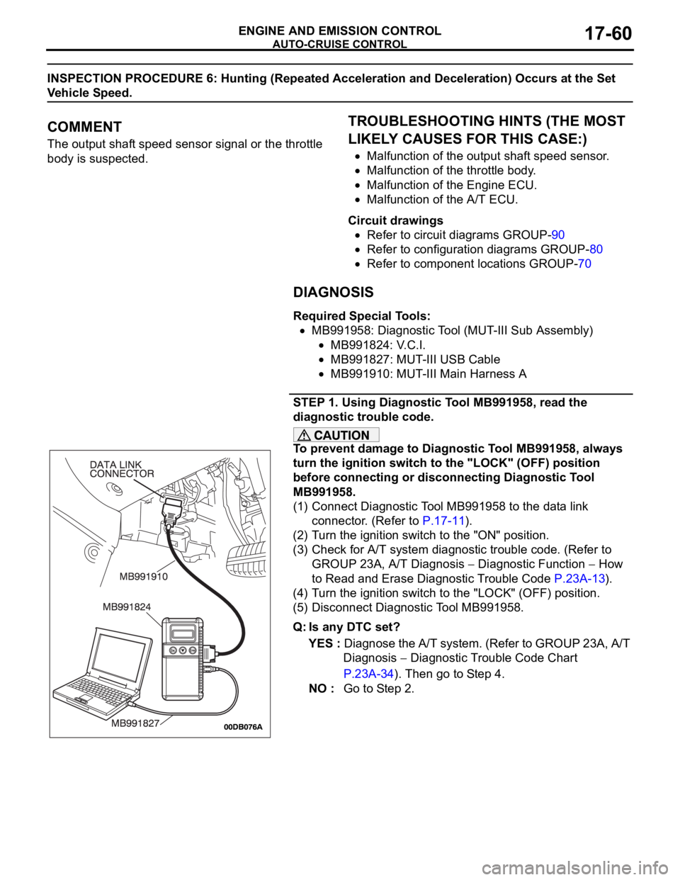
(1) Connect Diagnostic Tool MB991958 to the data link
connector. (Refer to P.17-11).
(2) Turn the ignition switch to the "ON" position.
(3) Check for A/T system diagnostic trouble code. (Refer to
GROUP 23A, A/T Diagnosis
Diagnostic Function How
to Read and Erase Diagnostic Trouble Code P.23A-13).
(4) Turn the ignition switch to the "LOCK" (OFF) position.
(5) Disconnect Diagnostic Tool MB991958.
Q: Is any DTC set?
YES : Diagnose the A/T system. (Refer to GROUP 23A, A/T
Diagnosis
Diagnostic Trouble Code Chart
P.23A-34). Then go to Step 4.
NO : Go to Step 2.
Page 1394 of 1500

AUTO-CRUISE CONTROL
ENGINE AND EMISSION CONTROL17-63
CIRCUIT OPERATION
The Engine ECU detects "CRUISE" (MAIN) switch
"ON" signal to illuminate the "CRUISE" indicator
lamp on the combination meter.
.
COMMENT
Connector(s), wiring harness in the CAN bus line
between the Engine ECU and the combination
meter, power supply to the Engine ECU, the combi-
nation meter, the Engine ECU may be defective.
.
TROUBLESHOOTING HINTS
Malfunction of the combination meter.
Damaged harness or connector.
Malfunction of the Engine ECU.
Circuit drawings
Refer to circuit diagrams GROUP-90
Refer to configuration diagrams GROUP-80
Refer to component locations GROUP-70
DIAGNOSIS
Required Special Tools:
MB991958: Diagnostic Tool (MUT-III Sub Assembly)
MB991824: V.C.I.
MB991827: MUT-III USB Cable
MB991910: MUT-III Main Harness A
STEP 1. Using Diagnostic Tool MB991958, diagnose the
CAN bus line.
To prevent damage to Diagnostic Tool MB991958, always
turn the ignition switch to the "LOCK" (OFF) position
before connecting or disconnecting Diagnostic Tool
MB991958.
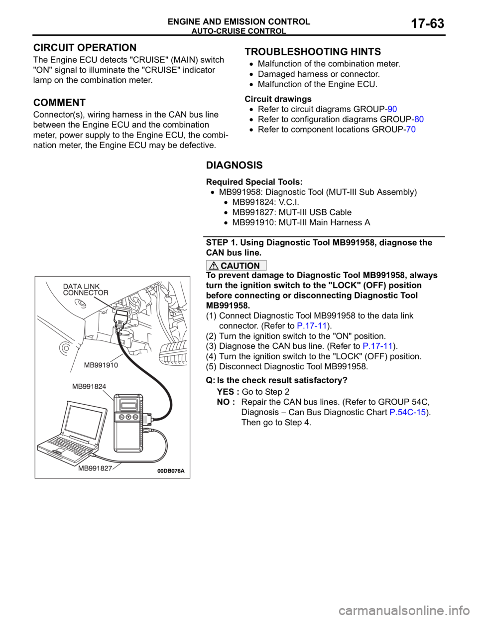
(1) Connect Diagnostic Tool MB991958 to the data link
connector. (Refer to P.17-11).
(2) Turn the ignition switch to the "ON" position.
(3) Diagnose the CAN bus line. (Refer to P.17-11).
(4) Turn the ignition switch to the "LOCK" (OFF) position.
(5) Disconnect Diagnostic Tool MB991958.
Q: Is the check result satisfactory?
YES : Go to Step 2
NO : Repair the CAN bus lines. (Refer to GROUP 54C,
Diagnosis
Can Bus Diagnostic Chart P.54C-15).
Then go to Step 4.
Page 1493 of 1500

AUTOMATIC TRANSMISSION DIAGNOSIS
AUTOMATIC TRANSMISSION23A-34
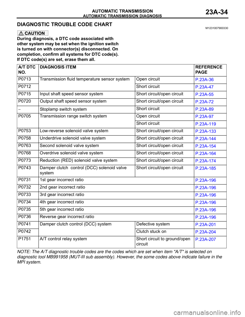
DIAGNOSTIC TROUBLE CODE CHARTM1231007900330
During diagnosis, a DTC code associated with
other system may be set when the ignition switch
is turned on with connector(s) disconnected. On
completion, confirm all systems for DTC code(s).
If DTC code(s) are set, erase them all.
NOTE: The A/T diagnostic trouble codes are the codes which are set when item "A/T" is selected on
diagnostic tool MB991958 (MUT-III sub assembly). However, the some codes above indicate failure in the
MPI system.A/T DTC
NO.DIAGNOSIS ITEM REFERENCE
PA G E
P0713 Transmission fluid temperature sensor system Open circuit
P.23A-36
P0712 Short circuit
P.23A-47
P0715 Input shaft speed sensor system Short circuit/open circuit
P.23A-55
P0720 Output shaft speed sensor system Short circuit/open circuit
P.23A-72
Stoplamp switch systemShort circuit
P.23A-89
P0705 Transmission range switch system Open circuit
P.23A-97
Short circuit
P.23A-119
P0753 Low-reverse solenoid valve system Short circuit/open circuit
P.23A-133
P0758 Underdrive solenoid valve system Short circuit/open circuit
P.23A-144
P0763 Second solenoid valve system Short circuit/open circuit
P.23A-154
P0768 Overdrive solenoid valve system Short circuit/open circuit
P.23A-164
P0773 Reduction (RED) solenoid valve system Short circuit/open circuit
P.23A-174
P0743 Damper clutch control (DCC) solenoid valve
systemShort circuit/open circuit
P.23A-185
P0731 1st gear incorrect ratio
P.23A-196
P0732 2nd gear incorrect ratio
P.23A-196
P0733 3rd gear incorrect ratio
P.23A-196
P0734 4th gear incorrect ratio
P.23A-196
P0735 5th gear incorrect ratio
P.23A-196
P0736 Reverse gear incorrect ratio
P.23A-196
P0741 Damper clutch control (DCC) system Defective system
P.23A-201
P0742 Clutch stuck on
P.23A-204
P1751 A/T control relay system Short circuit to ground/open
circuitP.23A-207