Ignition circuit MITSUBISHI 380 2005 Workshop Manual
[x] Cancel search | Manufacturer: MITSUBISHI, Model Year: 2005, Model line: 380, Model: MITSUBISHI 380 2005Pages: 1500, PDF Size: 47.87 MB
Page 793 of 1500
AUTO A/C DIAGNOSIS
HEATER, AIR CONDITIONING AND VENTILATION55-92
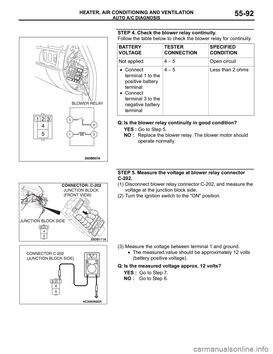
STEP 4. Check the blower relay continuity.
Follow the table below to check the blower relay for continuity.
Q: Is the blower relay continuity in good condition?
YES : Go to Step 5.
NO : Replace the blower relay. The blower motor should
operate normally.
STEP 5. Measure the voltage at blower relay connector
C-202.
(1) Disconnect blower relay connector C-202, and measure the
voltage at the junction block side.
(2) Turn the ignition switch to the "ON" position.
(3) Measure the voltage between terminal 1 and ground.
The measured value should be approximately 12 volts
(battery positive voltage).
Q: Is the measured voltage approx. 12 volts?
YES : Go to Step 7.
NO : Go to Step 6. BATTERY
VOLTAGETESTER
CONNECTIONSPECIFIED
CONDITION
Not applied 4
5 Open circuit
Connect
terminal 1 to the
positive battery
terminal
Connect
terminal 3 to the
negative battery
terminal4
5 Less than 2 ohms
Page 805 of 1500
AUTO A/C DIAGNOSIS
HEATER, AIR CONDITIONING AND VENTILATION55-104
INSPECTION PROCEDURE 7: The A/C Indicator Flashes.
.
TECHNICAL DESCRIPTION (COMMENT)
If the A/C indicator flashes, inadequate refrigerant
quantity, the ambient air temperature sensor circuit
or the A/C pressure sensor circuit is suspected.
.
TROUBLESHOOTING HINTS
Malfunction of the A/C pressure sensor
Malfunction of the ambient air temperature sen-
sor
Malfunction of the A/C-ECU
Refer to component locations GROUP-70
Refer to configuration diagrams GROUP-80
Refer to circuit diagrams GROUP-90
DIAGNOSIS
Required Special Tools:
MB991223: Test Harness Set
: Scan Tool (MUT-III Sub Assembly)
MB991824: Vehicle Communication Interface (V.C.I.)
MB991827: MUT-III USB Cable
MB991910: MUT-III Main Harness A (Vehicles with CAN
communication system)
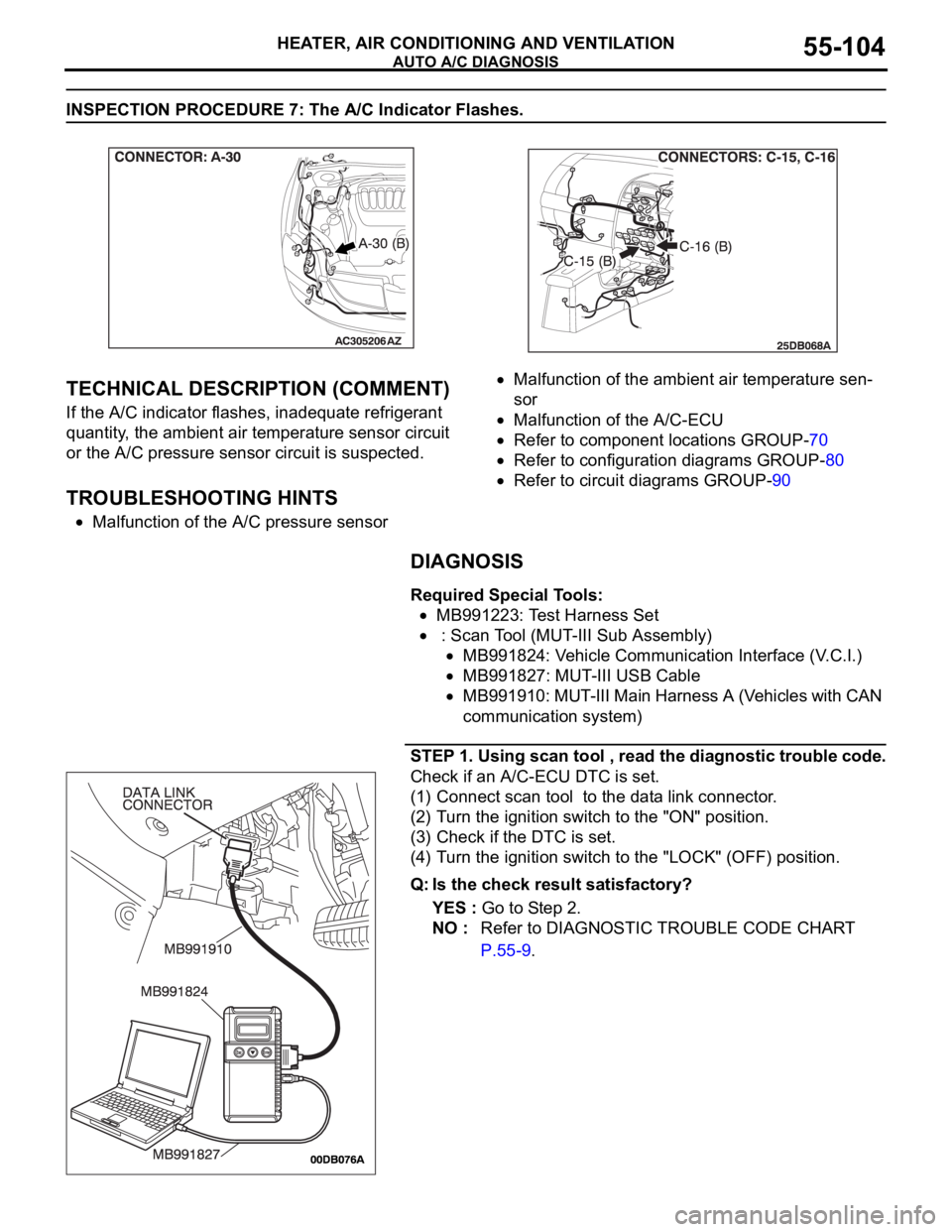
STEP 1. Using scan tool , read the diagnostic trouble code.
Check if an A/C-ECU DTC is set.
(1) Connect scan tool to the data link connector.
(2) Turn the ignition switch to the "ON" position.
(3) Check if the DTC is set.
(4) Turn the ignition switch to the "LOCK" (OFF) position.
Q: Is the check result satisfactory?
YES : Go to Step 2.
NO : Refer to DIAGNOSTIC TROUBLE CODE CHART
P.55-9.
Page 907 of 1500
HOW TO DIAGNOSE
GENERAL
5. Ohmmeter
An ohmmeter is used to check continuity or measure
resistance of a switch or coil. If the measuring range has
been changed, the zero point must be adjusted before
measurement.
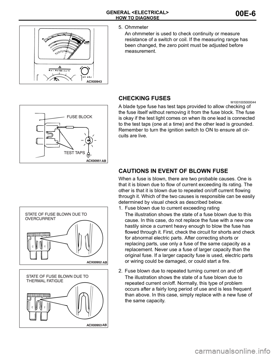
CHECKING FUSESM1001005000044
A blade type fuse has test taps provided to allow checking of
the fuse itself without removing it from the fuse block. The fuse
is okay if the test light comes on when its one lead is connected
to the test taps (one at a time) and the other lead is grounded.
Remember to turn the ignition switch to ON to ensure all cir-
cuits are live.
CAUTIONS IN EVENT OF BLOWN FUSE
When a fuse is blown, there are two probable causes. One is
that it is blown due to flow of current exceeding its rating. The
other is that it is blown due to repeated on/off current flowing
through it. Which of the two causes is responsible can be easily
determined by visual check as described below.
1. Fuse blown due to current exceeding rating
The illustration shows the state of a fuse blown due to this
cause. In this case, do not replace the fuse with a new one
hastily since a current heavy enough to blow the fuse has
flowed through it. First, check the circuit for shorts and check
for abnormal electric parts. After correcting shorts or
replacing parts, use only a fuse of the same capacity as a
replacement. Never use a fuse of larger capacity than the
original fuse. If a larger capacity fuse is used, electric parts
or wiring could be damaged, or could start a fire.
2. Fuse blown due to repeated turning current on and off
The illustration shows the state of a fuse blown due to
repeated current on/off. Normally, this type of problem
occurs after a fairly long period of use and is less frequent
than above. In this case, simply replace with a new fuse of
the same capacity.
Page 980 of 1500
CHARGING SYSTEM
ENGINE ELECTRICAL16-3
CHARGING SYSTEM DIAGNOSISM1161000700427
TROUBLESHOOTING HINTS
Alternator malfunction light dose not go on when the ignition
switch is turned to ON, before the engine starts.
Check the bulb.
Alternator malfunction light dose not switch off after the engine
starts.
Check the IC voltage regulator inside the
alternatoralternator.
Discharged or overcharged battery.
Check the IC voltage regulator inside the alternator.
The alternator malfunction light illuminates dimly.
Check the diode (inside the combination meter) for a
short-circuit.
TROUBLESHOOTING GUIDE
The charging system troubleshooting guide is shown in the fol-
lowing steps.
STEP 1.
Q: Is the battery in good condition? (Refer to GROUP 54A,
Chassis Electrical
Battery On-vehicle Service
Battery Check P.54A-5.)
YES : Go to Step 2.
NO : Charge or replace the battery.
STEP 2.
Q: Is the alternator drive belt in good condition? (Refer to
GROUP 00, General
Maintenance Service Drive Belts
(For Alternator, Power Steering Pump and Air
Conditioning) (Check) P.00-39.)
YES : Go to Step 3.
NO : Adjust the belt tension or replace the belt.
STEP 3.
Q: Does the alternator malfunction light come on when the
ignition switch is turned on?
YES : Go to Step 4.
NO :
Check the ignition switch. (Refer to GROUP 54A,
Chassis Electrical
Ignition Switch Ignition
Switch
Inspection P.54A-44.)
Check for burnt-out alternator malfunction light.
Check the alternator. (Refer to Charging System
Alternator Assembly
Inspection P.16-17.)
Check the alternator malfunction light-related
circuits.
Page 986 of 1500
CHARGING SYSTEM
ENGINE ELECTRICAL16-9
Required Special Tool:
: Diagnostic Tool (MUT-III)
MB991824: V.C.I.
MB991827: MUT-III USB Cable
MB991910: MUT-III Main Harness A
This test determines whether the alternator outputs
normal current. For best results, use a charging sys-
tem tester. If not available, follow the steps below.
Battery posts, terminals and related acces-
sories contain lead and lead compounds.
WASH HANDS AFTER HANDLING.
1. Before the test, always be sure to check the
following.
Alternator installation
Battery (Refer to GROUP 54A, Chassis Electrical
Battery On-vehicle Service Battery Check
P.54A-5.)
NOTE: The battery to be used should be slightly
discharged. The load in a fully-charged battery
will be insufficient and the test may not be able to
be carried out correctly.
Alternator drive belt tension (Refer to GROUP 00,
General
Maintenance Service Drive Belts
(For Alternator, Power Steering Pump and Air
Conditioning) (Check) P.00-39.)
Fusible link
Abnormal noise from the alternator while the
engine is running.
2. Turn the ignition switch to the "LOCK" (OFF)
position.
3. Disconnect the negative battery cable.
Never use clips to connect the wire. Loose
connections (for example, using clips) will
lead to a serious accident because of high
current.
4. Connect a clamp-type DC test ammeter with a
range of 0
120 A to the alternator "B" terminal
output wire.
5. Connect a voltmeter with a range of 0
20 V
between the alternator "B" terminal and ground.
(Connect the positive lead of the voltmeter to the
"B" terminal, and then connect the negative lead
of the voltmeter to ground.)
6. Connect the negative battery cable.
7. Connect an engine tachometer or diagnostic tool.
8. Leave the hood open.9. Check to be sure that the reading on the voltmeter
is equal to the battery positive voltage.
NOTE: If the voltage is 0 V, the cause is probably
an open circuit in the wire or fusible link between
the alternator "B" terminal and the battery positive
terminal or malfunctioning voltmeter.
10.After turning on the headlights, start the engine.
NOTE: Because the current from the battery will
soon drop after the engine is started, step 11
should be carried out as quickly as possible in
order to obtain the maximum current output value.
11.Immediately after setting the headlights to high
beam and turning the heater blower switch to the
highest position, increase the engine speed to
2,500 r/min and read the maximum current output
value displayed on the ammeter.
Limit value: 70 % of nominal current output
NOTE: For the nominal current output, refer to the
Alternator Specifications.
NOTE: The current output value will depend on
the electrical load and the temperature of the
alternator body.
NOTE: If the electrical load is small while testing,
the specified level of current may not be output
even though the alternator is normal. In such
cases, increase the electrical load by leaving the
headlights turned on for some time to discharge
the battery or by using the lighting system in
another vehicle, and then test again.
NOTE: The specified level of current also may not
be output if the temperature of the alternator body
or the ambient temperature is too high. In such
cases, cool the alternator and then test again.
12.The reading on the ammeter should be above the
limit value. If the reading is below the limit value
and the alternator output wire is normal, remove
the alternator from the engine and check the
alternator.
13.Run the engine at idle speed after the test.
14.Turn the ignition switch to the "LOCK" (OFF)
position.
15.Disconnect the engine tachometer or diagnostic
tool.
16.Disconnect the negative battery cable.
17.Disconnect the ammeter and voltmeter .
18.Connect the negative battery cable.
19.Run the engine for 10 minutes at an idle.
Page 987 of 1500
CHARGING SYSTEM
ENGINE ELECTRICAL16-10
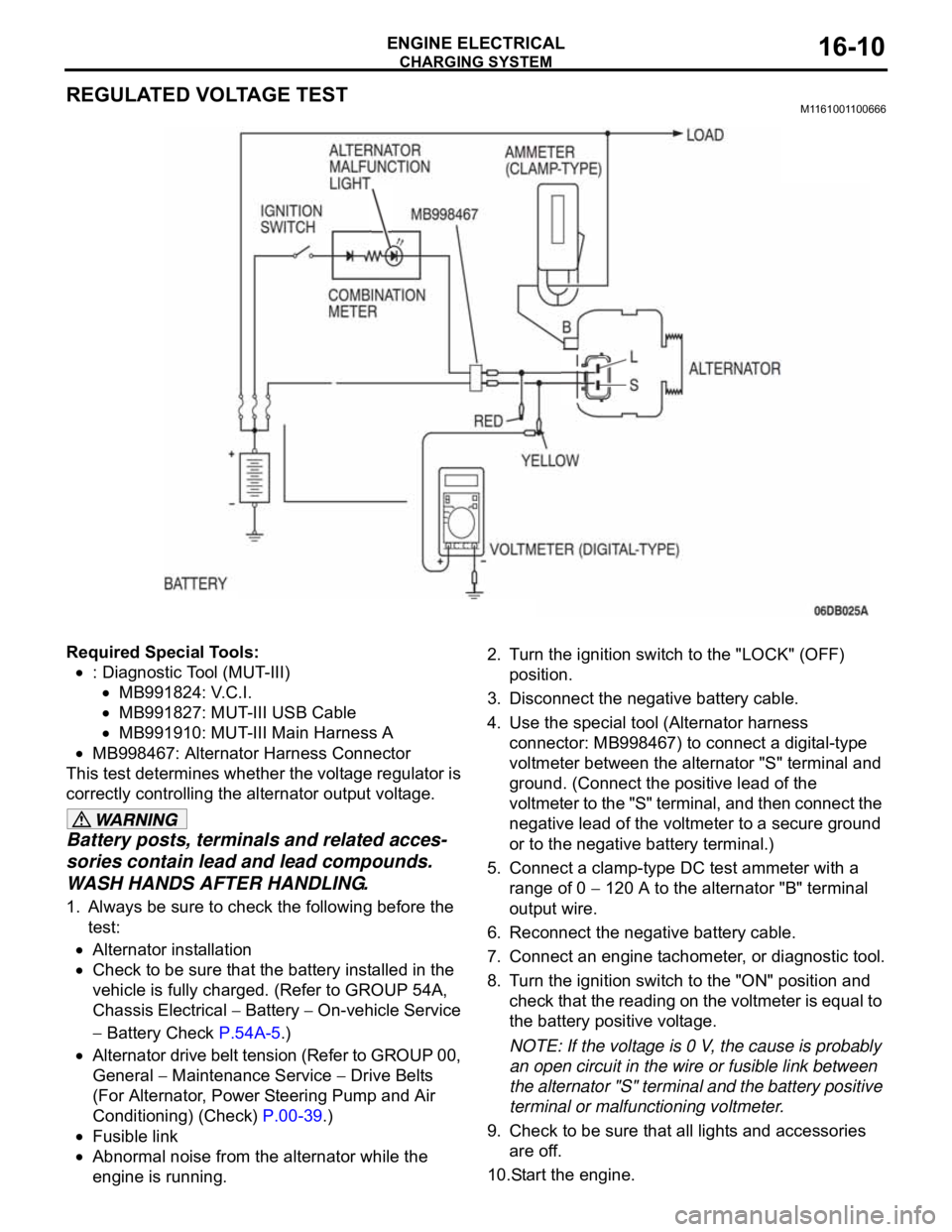
REGULATED VOLTAGE TESTM1161001100666
Required Special Tools:
: Diagnostic Tool (MUT-III)
MB991824: V.C.I.
MB991827: MUT-III USB Cable
MB991910: MUT-III Main Harness A
MB998467: Alternator Harness Connector
This test determines whether the voltage regulator is
correctly controlling the alternator output voltage.
Battery posts, terminals and related acces-
sories contain lead and lead compounds.
WASH HANDS AFTER HANDLING.
1. Always be sure to check the following before the
test:
Alternator installation
Check to be sure that the battery installed in the
vehicle is fully charged. (Refer to GROUP 54A,
Chassis Electrical
Battery On-vehicle Service
Battery Check P.54A-5.)
Alternator drive belt tension (Refer to GROUP 00,
General
Maintenance Service Drive Belts
(For Alternator, Power Steering Pump and Air
Conditioning) (Check) P.00-39.)
Fusible link
Abnormal noise from the alternator while the
engine is running.2. Turn the ignition switch to the "LOCK" (OFF)
position.
3. Disconnect the negative battery cable.
4. Use the special tool (Alternator harness
connector: MB998467) to connect a digital-type
voltmeter between the alternator "S" terminal and
ground. (Connect the positive lead of the
voltmeter to the "S" terminal, and then connect the
negative lead of the voltmeter to a secure ground
or to the negative battery terminal.)
5. Connect a clamp-type DC test ammeter with a
range of 0
120 A to the alternator "B" terminal
output wire.
6. Reconnect the negative battery cable.
7. Connect an engine tachometer, or diagnostic tool.
8. Turn the ignition switch to the "ON" position and
check that the reading on the voltmeter is equal to
the battery positive voltage.
NOTE: If the voltage is 0 V, the cause is probably
an open circuit in the wire or fusible link between
the alternator "S" terminal and the battery positive
terminal or malfunctioning voltmeter.
9. Check to be sure that all lights and accessories
are off.
10.Start the engine.
Page 1008 of 1500

IGNITION SYSTEM
ENGINE ELECTRICAL16-31
ON-VEHICLE SERVICE
KNOCK CONTROL SYSTEM CHECKM1163001800081
Check the knock sensor circuit if diagnostic trouble code, No.
P0325 is shown.
Refer to GROUP 13B, Multiport Fuel Injection (MPI)
Multiport
Fuel Injection (MPI) Diagnosis
Diagnostic Trouble Code Pro-
cedures
DTC P0325 : Knock Sensor Circuit 13A-346.
IGNITION COIL CHECK M1163001200380
Check by the following procedure, and replace the coil if there
is a malfunction.
.
PRIMARY COIL AND IGNITION POWER
TRANSISTOR CONTINUITY CHECK
NOTE: No test can be performed on the Primary side of coil.
.
SECONDARY COIL CHECK
NOTE: It is impossible to check the secondary coil through the
continuity check as a diode is integrated in the secondary coil
circuit of this ignition coil. Accordingly, check the secondary coil
in the following procedure.
1. Disconnect the ignition coil connector.
2. Remove the ignition coil and install a new spark plug to the
ignition coil.
3. Connect the ignition coil connector.
4. Disable vehicle fuel pump by removing fuel pump relay or
disconnecting fuel pump connector D-18 (under rear seat).
5. Ground the side electrode of the spark plug and crank the
engine.
6. Check that spark is produced between the electrodes of the
spark plug.
7. If no spark is produced, replace the ignition coil with a new
one and recheck.
8. If spark is produced with the new ignition coil, replace the
old one as it is faulty. If no spark is produced again, the
ignition circuit is suspected as faulty. Check the ignition
circuit.
Page 1009 of 1500
IGNITION SYSTEM
ENGINE ELECTRICAL16-32
SPARK PLUG TESTM1163001500143
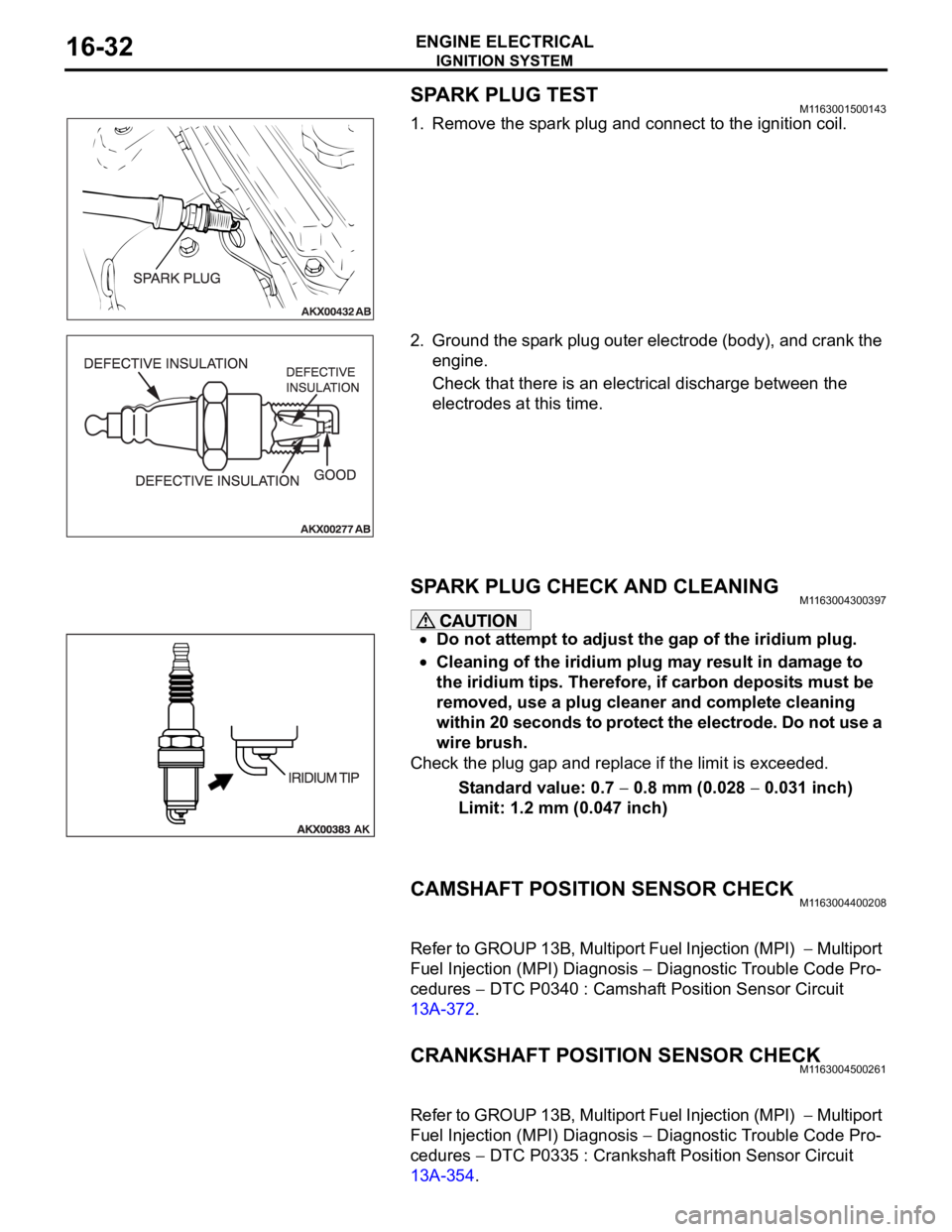
1. Remove the spark plug and connect to the ignition coil.
2. Ground the spark plug outer electrode (body), and crank the
engine.
Check that there is an electrical discharge between the
electrodes at this time.
SPARK PLUG CHECK AND CLEANING M1163004300397
Do not attempt to adjust the gap of the iridium plug.
Cleaning of the iridium plug may result in damage to
the iridium tips. Therefore, if carbon deposits must be
removed, use a plug cleaner and complete cleaning
within 20 seconds to protect the electrode. Do not use a
wire brush.
Check the plug gap and replace if the limit is exceeded.
Standard value: 0.7
0.8 mm (0.028 0.031 inch)
Limit: 1.2 mm (0.047 inch)
CAMSHAFT POSITION SENSOR CHECKM1163004400208
Refer to GROUP 13B, Multiport Fuel Injection (MPI) Multiport
Fuel Injection (MPI) Diagnosis
Diagnostic Trouble Code Pro-
cedures
DTC P0340 : Camshaft Position Sensor Circuit
13A-372.
CRANKSHAFT POSITION SENSOR CHECKM1163004500261
Refer to GROUP 13B, Multiport Fuel Injection (MPI) Multiport
Fuel Injection (MPI) Diagnosis
Diagnostic Trouble Code Pro-
cedures
DTC P0335 : Crankshaft Position Sensor Circuit
13A-354.
Page 1143 of 1500
SUNROOF ASSEMBLY
BODY42-76
SUNROOF TIMER FUNCTION CHECKM1426004300100
Keep the door closed, turn OFF the ignition switch and check to
see if the sunroof can be operated for 30 seconds after that. If
not, perform troubleshooting (Refer to GROUP 54B, SWS
Diagnosis P.54B-57).
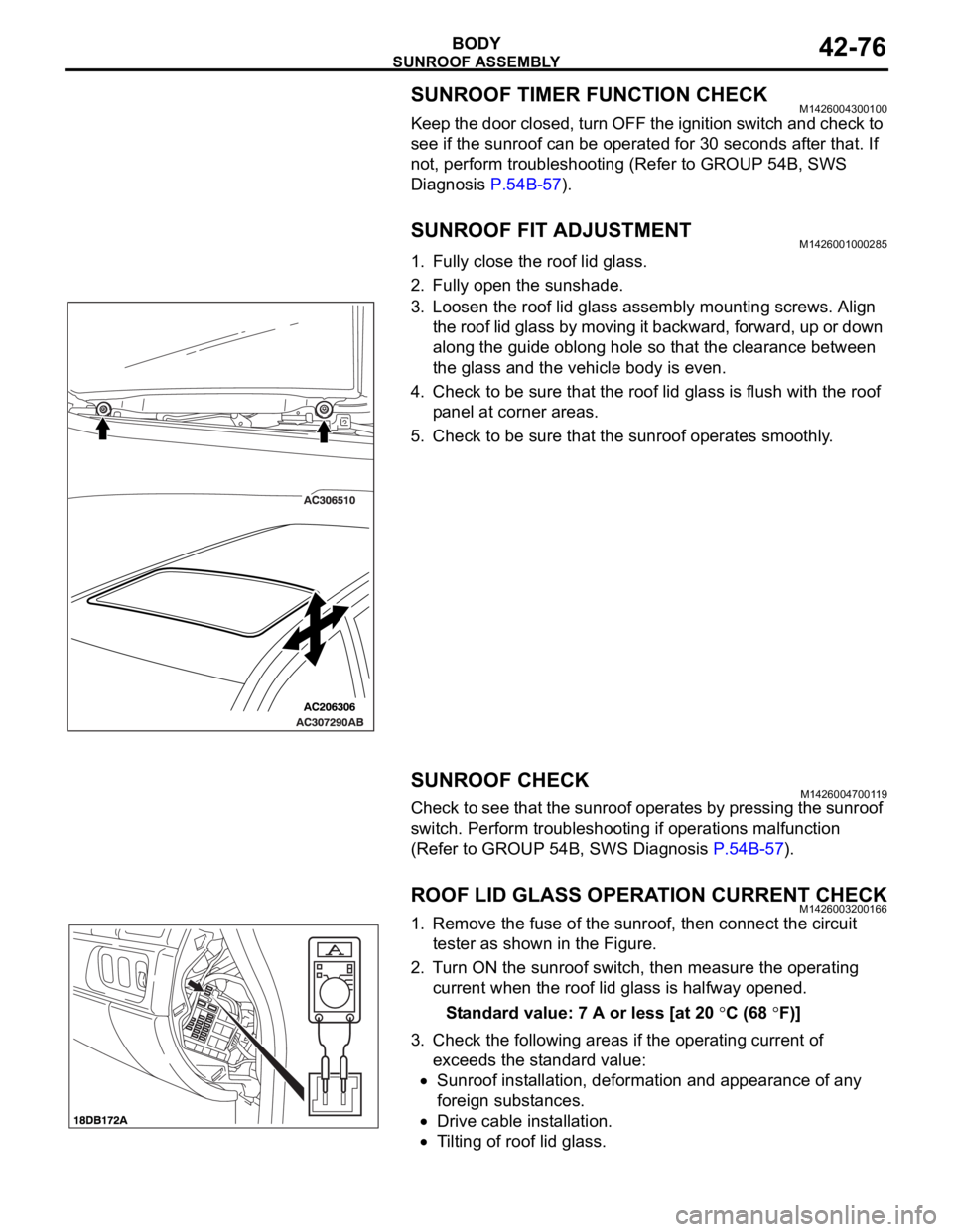
SUNROOF FIT ADJUSTMENTM1426001000285
1. Fully close the roof lid glass.
2. Fully open the sunshade.
3. Loosen the roof lid glass assembly mounting screws. Align
the roof lid glass by moving it backward, forward, up or down
along the guide oblong hole so that the clearance between
the glass and the vehicle body is even.
4. Check to be sure that the roof lid glass is flush with the roof
panel at corner areas.
5. Check to be sure that the sunroof operates smoothly.
SUNROOF CHECKM1426004700119
Check to see that the sunroof operates by pressing the sunroof
switch. Perform troubleshooting if operations malfunction
(Refer to GROUP 54B, SWS Diagnosis P.54B-57).
ROOF LID GLASS OPERATION CURRENT CHECKM1426003200166
1. Remove the fuse of the sunroof, then connect the circuit
tester as shown in the Figure.
2. Turn ON the sunroof switch, then measure the operating
current when the roof lid glass is halfway opened.
Standard value: 7 A or less [at 20
C (68 F)]
3. Check the following areas if the operating current of
exceeds the standard value:
Sunroof installation, deformation and appearance of any
foreign substances.
Drive cable installation.
Tilting of roof lid glass.
Page 1228 of 1500
HOW TO USE TROUBLESHOOTING/INSPECTION SERVICE POINTS
GENERAL00-7
HOW TO USE TROUBLESHOOTING/INSPECTION SERVICE
POINTS
TROUBLESHOOTING CONTENTSM1001013300062
During diagnosis, a DTC code associated with
other system may be set when the ignition
switch is turned on with connector(s) discon-
nected. On completion, confirm all systems
for DTC code(s). If DTC code(s) are set, erase
them all.
When the DIAGNOSTIC TOOL (MUT-III)
detects a diagnostic trouble code, its display
informs users whether a mechanical problem
currently exists (“current trouble”) or whether
it existed before but normal operation has
been restored (“past trouble”). However, if an
MPI, TPMS or SRS airbag-related DTC is set,
“Active DTC/Stored DTC” is not displayed. In
this case, follow the diagnosis procedure for
current trouble.
If a trouble, detected in a CAN communica-
tion-capable system, can be reproduced,
diagnose the CAN bus lines (Refer to GROUP
54C, Can Bus Line Diagnostics Chart
P.54C-15 or P.54C-15).
Troubleshooting of electronic control systems for
which the MUT -III can be used follows the basic out-
line described below. Even in systems for which the
MUT-III cannot be used, part of these systems still
follow this outline.
1. STANDARD FLOW OF DIAGNOSTIC
TROUBLESHOOTING
Troubleshooting strategy is shown in each group.
2. SYSTEM OPERATION AND SYMPTOM
VERIFICATION TESTS
If verification of the symptom(s) is difficult, proce-
dures for checking operation and verifying symptoms
are shown.
3. DIAGNOSTIC FUNCTION
The following trouble code diagnoses are shown.
How to read diagnostic trouble codes
How to erase diagnostic trouble codes
Input inspection service points
4. DIAGNOSTIC TROUBLE CODE CHART
If the MUT-III displays a diagnostic trouble code, find
the applicable inspection procedure according to this
chart.
5. SYMPTOM CHART
If there are symptoms, even though the MUT-III
shows that no DTCs are set, inspection procedures
for each symptom will be found by using this chart.
6. DIAGNOSTIC TROUBLE CODE
PROCEDURES
Indicates the inspection procedures corresponding to
each diagnostic trouble code. (Refer to P.00-9).
7. SYMPTOM PROCEDURES
Indicates the inspection procedures corresponding to
each symptom listed in the Symptom Chart (Refer to
P.00-9).
8. SERVICE DATA REFERENCE TABLE
Inspection items and normal judgment values have
been provided in this chart as reference information.
9. CHECK AT ECU TERMINALS
Terminal numbers for the ECU connectors, inspec-
tion items, and standard values have been provided
in this chart as reference information.
.
TERMINAL VOLTAGE CHECKS
1. Use correct tool to check each pin location on the
ENGINE-ECU Check harnes MB992044 and
measure with voltmeter.
Short-circuiting the positive (+) test probe
between a connector terminal and ground could
damage the vehicle wiring, the sensor, the ECU,
or all three. Use care to prevent this!
2. Insert the correct terminal tool into each of the
ENGINE-ECU check harness connector
terminals, and measure the voltage while referring
to the check chart.
NOTE: Measure voltage with the ECU connectors
connected.
You may find it convenient to pull out the ECU to
make it easier to connect the ENGINE-ECU check
harness.