Ignition circuit MITSUBISHI 380 2005 Workshop Manual
[x] Cancel search | Manufacturer: MITSUBISHI, Model Year: 2005, Model line: 380, Model: MITSUBISHI 380 2005Pages: 1500, PDF Size: 47.87 MB
Page 1313 of 1500
TRACTION CONTROL SYSTEM (TCL) DIAGNOSIS
TRACTION CONTROL SYSTEM (TCL)13C-34
INSPECTION PROCEDURE 6: TCL does not Operate.
NOTE: If the ABS-8 ECU or the active wheel
speed sensor are disconnected, or if the wiring is
an open/ short circuit, the ABS 8 ECU will shut
off power supply to the respective wheel speed
sensor. All other wheel speed sensors will oper-
ate normally. To restore the power supply, the
ignition switch must be turned to the "OFF" posi-
tion then to the "ON" position again.
.
COMMENT
The fail-safe function is probably cancelling TCL. In
this case, diagnostic tool MB991958 can be used to
retest each system by checking the diagnostic trou-
ble codes.
.
TROUBLESHOOTING HINTS (THE MOST
LIKELY CAUSES FOR THIS CASE:)
Malfunction of the CAN bus line.
Malfunction of the MPI system.
Malfunction of the A/T system.
Malfunction of the ABS/TCL-ECU.
DIAGNOSIS
Required Special Tools:
MB991958: Diagnostic Tool (MUT-III Sub Assembly)
MB991824: V.C.I.
MB991827: MUT-III USB Cable
MB991910: MUT-III Main Harness A
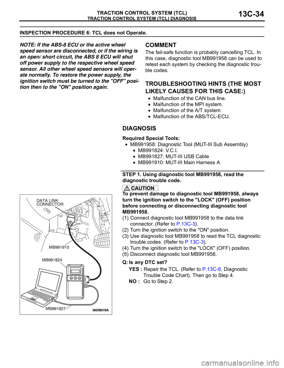
STEP 1. Using diagnostic tool MB991958, read the
diagnostic trouble code.
To prevent damage to diagnostic tool MB991958, always
turn the ignition switch to the "LOCK" (OFF) position
before connecting or disconnecting diagnostic tool
MB991958.
(1) Connect diagnostic tool MB991958 to the data link
connector. (Refer to P.13C-3).
(2) Turn the ignition switch to the "ON" position.
(3) Use diagnostic tool MB991958 to read the TCL diagnostic
trouble codes. (Refer to P.13C-3).
(4) Turn the ignition switch to the "LOCK" (OFF) position.
(5) Disconnect diagnostic tool MB991958.
Q: Is any DTC set?
YES : Repair the TCL. (Refer to P.13C-8, Diagnostic
Trouble Code Chart). Then go to Step 4.
NO : Go to Step 2.
Page 1315 of 1500

TRACTION CONTROL SYSTEM (TCL) DIAGNOSIS
TRACTION CONTROL SYSTEM (TCL)13C-36
DATA LIST REFERENCE TABLEM1136003500071
NOTE: If the ABS-8 ECU or the active wheel
speed sensor are disconnected, or if the wiring is
an open/ short circuit, the ABS 8 ECU will shut
off power supply to the respective wheel speed
sensor. All other wheel speed sensors will oper-
ate normally. To restore the power supply, the
ignition switch must be turned to the "OFF" posi-
tion then to the "ON" position again.The following items can be read by the diagnostic
tool from the ABS/TCL-ECU input data. (Refer to
P.13C-3).
NOTE: Since the TCL is controlled with the same ABS/TCL-ECU used to control the ABS, the stoplight switch
check item (No.6) used only for the ABS also appear.MUT-III
DIAGNOSTI
C TOOL
DISPLAYITEM
NO.CHECK ITEM CHECKING REQUIREMENTS NORMAL
VA L U E
FL wheel
speed sensor01 Front left wheel speed sensor Drive the vehicle Vehicle speeds
displayed on the
speedometer
and diagnostic
tool are identical. FR wheel
speed sensor02 Front right wheel speed sensor
RL wheel
speed sensor03 Rear left wheel speed sensor
RR wheel
speed sensor04 Rear right left wheel speed
sensor
Power supply
voltage05 ABS/TCL-ECU power supply
voltageIgnition switch power supply
voltageBattery positive
voltage
Stoplamp
switch
(input)*06 Stoplamp switch Depress the brake pedal. ON
Release the brake pedal. OFF
Stoplamp
switch*13 Stoplamp switch Depress the brake pedal. ON
Release the brake pedal. OFF
Pump motor 21 Pump motor When the ABS outputs the
operation permission signal
during drivingON
When the ABS outputs the
operation permission signal
during drivingOFF
Valve relay 30 Valve relayWhen the ABS outputs the
operation permission signal
during drivingON
When the ABS outputs the
operation permission signal
during drivingOFF
TCL mode 35 TCL operation When the TCL outputs the
operation permission signal
during drivingON
When the TCL outputs the
operation inhibition signal
during drivingOFF
Page 1316 of 1500

TRACTION CONTROL SYSTEM (TCL) DIAGNOSIS
TRACTION CONTROL SYSTEM (TCL)13C-37
ACTUATOR TEST REFERENCE TABLEM1136003600067
NOTE: If the ABS-8 ECU or the active wheel
speed sensor are disconnected, or if the wiring is
an open/ short circuit, the ABS 8 ECU will shut
off power supply to the respective wheel speed
sensor. All other wheel speed sensors will oper-
ate normally. To restore the power supply, the
ignition switch must be turned to the "OFF" posi-
tion then to the "ON" position again.The diagnostic tool activates the following actuators
for testing. (Refer to P.13C-3).
NOTE: Since the TCL is controlled with the same ABS/TCL-ECU used to control the ABS, the FL, FR, RL or
RR Wheel ABS Drive testing items (No.01 to 04) used only for the ABS also appear. MUT-III
DIAGNOSTIC TOOL
DISPLAYITEM NO. CHECK ITEM PARTS TO BE ACTIVATED
FL wheel ABS Drive* 01 Solenoid valve for front left wheel Solenoid valves and pump
motors in the hydraulic unit
(simple inspection mode) FR wheel ABS Drive* 02 Solenoid valve for front right wheel
RL wheel ABS Drive* 03 Solenoid valve for rear left wheel
RR wheel ABS
Drive*04 Solenoid valve for rear right wheel
Engine TCL Drive 09 TCL operation check Outputs the engine torque
control signal (engine torque =
0) to PCM for three seconds.
Page 1317 of 1500
TRACTION CONTROL SYSTEM (TCL) DIAGNOSIS
TRACTION CONTROL SYSTEM (TCL)13C-38
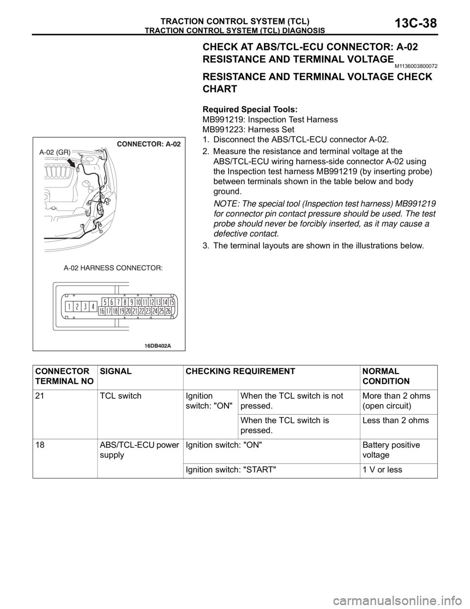
CHECK AT ABS/TCL-ECU CONNECTOR: A-02
RESISTANCE AND TERMINAL VOLTAGE
M1136003800072
RESISTANCE AND TERMINAL VOLTAGE CHECK
CHART
.
Required Special Tools:
MB991219: Inspection Test Harness
MB991223: Harness Set
1. Disconnect the ABS/TCL-ECU connector A-02.
2. Measure the resistance and terminal voltage at the
ABS/TCL-ECU wiring harness-side connector A-02 using
the Inspection test harness MB991219 (by inserting probe)
between terminals shown in the table below and body
ground.
NOTE: The special tool (Inspection test harness) MB991219
for connector pin contact pressure should be used. The test
probe should never be forcibly inserted, as it may cause a
defective contact.
3. The terminal layouts are shown in the illustrations below.
CONNECTOR
TERMINAL NOSIGNAL CHECKING REQUIREMENT NORMAL
CONDITION
21 TCL switch Ignition
switch: "ON" When the TCL switch is not
pressed.More than 2 ohms
(open circuit)
When the TCL switch is
pressed.Less than 2 ohms
18 ABS/TCL-ECU power
supplyIgnition switch: "ON" Battery positive
voltage
Ignition switch: "START" 1 V or less
Page 1320 of 1500
TRACTION CONTROL SYSTEM (TCL) DIAGNOSIS
TRACTION CONTROL SYSTEM (TCL)13C-41
VOLTAGE AND SIGNAL CHECK AT ABS-ECU
(A-02) USING OSCILLOSCOPE
NOTE: If the ABS-8 ECU or the active wheel speed
sensor are disconnected, or if the wiring is an open/
short circuit, the ABS 8 ECU will shut off power sup-
ply to the respective wheel speed sensor. All other
wheel speed sensors will operate normally. To
restore the power supply, the ignition switch must be
turned to the "OFF" position then to the "ON" position
again..
WHEEL SPEED SENSOR AIR GAP:
Sensor air gap: (0.2mm - 0.85mm).
.
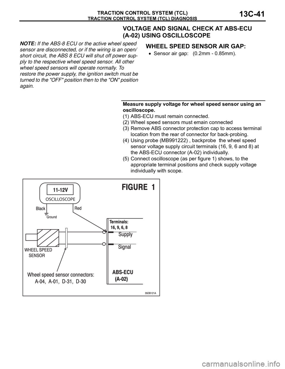
Measure supply voltage for wheel speed sensor using an
oscilloscope.
(1) ABS-ECU must remain connected.
(2) Wheel speed sensors must emain connected
(3) Remove ABS connector protection cap to access terminal
location from the rear of connector for back-probing.
(4) Using probe (MB991222) , backprobe the wheel speed
sensor voltage supply circuit terminals (16, 9, 6 and 8) at
the ABS-ECU connector (A-02) individually.
(5) Connect oscilloscope (as per figure 1) shows, to the
appropriate terminal positions and check supply voltage
individually with scope.
Page 1327 of 1500
ON-VEHICLE SERVICE
TRACTION CONTROL SYSTEM (TCL)13C-48
To prevent damage to diagnostic tool MB991958, always
turn the ignition switch to the "LOCK" (OFF) position
before connecting or disconnecting diagnostic tool
MB991958.
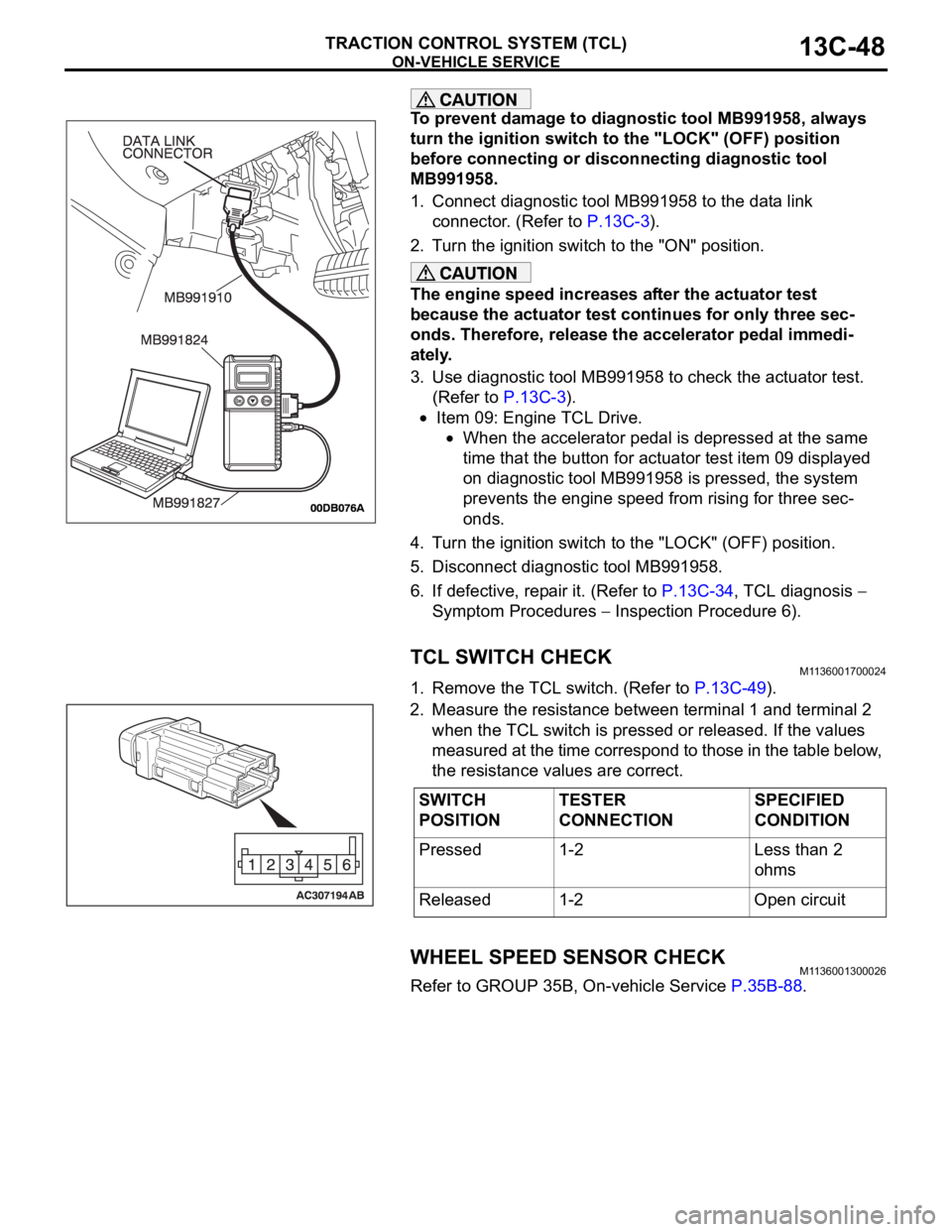
1. Connect diagnostic tool MB991958 to the data link
connector. (Refer to P.13C-3).
2. Turn the ignition switch to the "ON" position.
The engine speed increases after the actuator test
because the actuator test continues for only three sec-
onds. Therefore, release the accelerator pedal immedi-
ately.
3. Use diagnostic tool MB991958 to check the actuator test.
(Refer to P.13C-3).
Item 09: Engine TCL Drive.
When the accelerator pedal is depressed at the same
time that the button for actuator test item 09 displayed
on diagnostic tool MB991958 is pressed, the system
prevents the engine speed from rising for three sec-
onds.
4. Turn the ignition switch to the "LOCK" (OFF) position.
5. Disconnect diagnostic tool MB991958.
6. If defective, repair it. (Refer to P.13C-34, TCL diagnosis
Symptom Procedures
Inspection Procedure 6).
TCL SWITCH CHECKM1136001700024
1. Remove the TCL switch. (Refer to P.13C-49).
2. Measure the resistance between terminal 1 and terminal 2
when the TCL switch is pressed or released. If the values
measured at the time correspond to those in the table below,
the resistance values are correct.
WHEEL SPEED SENSOR CHECKM1136001300026
Refer to GROUP 35B, On-vehicle Service P.35B-88.
SWITCH
POSITIONTESTER
CONNECTIONSPECIFIED
CONDITION
Pressed 1-2 Less than 2
ohms
Released 1-2 Open circuit
Page 1349 of 1500
AUTO-CRUISE CONTROL
ENGINE AND EMISSION CONTROL17-18
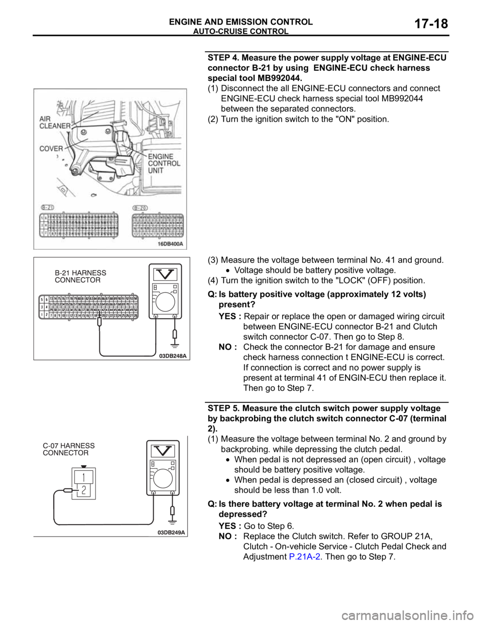
STEP 4. Measure the power supply voltage at ENGINE-ECU
connector B-21 by using ENGINE-ECU check harness
special tool MB992044.
(1) Disconnect the all ENGINE-ECU connectors and connect
ENGINE-ECU check harness special tool MB992044
between the separated connectors.
(2) Turn the ignition switch to the "ON" position.
(3) Measure the voltage between terminal No. 41 and ground.
Voltage should be battery positive voltage.
(4) Turn the ignition switch to the "LOCK" (OFF) position.
Q: Is battery positive voltage (approximately 12 volts)
present?
YES : Repair or replace the open or damaged wiring circuit
between ENGINE-ECU connector B-21 and Clutch
switch connector C-07. Then go to Step 8.
NO : Check the connector B-21 for damage and ensure
check harness connection t ENGINE-ECU is correct.
If connection is correct and no power supply is
present at terminal 41 of ENGIN-ECU then replace it.
Then go to Step 7.
STEP 5. Measure the clutch switch power supply voltage
by backprobing the clutch switch connector C-07 (terminal
2).
(1) Measure the voltage between terminal No. 2 and ground by
backprobing. while depressing the clutch pedal.
When pedal is not depressed an (open circuit) , voltage
should be battery positive voltage.
When pedal is depressed an (closed circuit) , voltage
should be less than 1.0 volt.
Q: Is there battery voltage at terminal No. 2 when pedal is
depressed?
YES : Go to Step 6.
NO : Replace the Clutch switch. Refer to GROUP 21A,
Clutch - On-vehicle Service - Clutch Pedal Check and
Adjustment P.21A-2. Then go to Step 7.
Page 1355 of 1500

AUTO-CRUISE CONTROL
ENGINE AND EMISSION CONTROL17-24
STEP 4. Check Engine ECU connector B-21 for loose,
corroded or damaged terminals, or terminals pushed back
in the connector.
Q: Are the connector and terminals in good condition?
YES : Go to Step 5.
NO : Repair the faulty connector if possible or as
recommended, replace complete wiring harness.
(Refer to GROUP 00E, Harness Connector Inspection
P.00E-2). Install the air bag module (driver’s side).
(Refer to GROUP 52B, Air Bag Modules and Clock
Spring P.52B-237). Then go to Step 18.
STEP 5. Check the harness for short circuit to ground
between the Engine ECU connector B-21 terminal 14 and
the auto-cruise control switch connector C-302 terminal 2.
(1) Disconnect Engine ECU connector B-21 and measure at
the harness connector side.
(2) Turn the ignition switch to the "LOCK" (OFF) position.
(3) Measure the continuity between Engine ECU connector
B-21 terminal 14 and ground.
(4) Reconnect Engine ECU connector B-21.
Q: Is the measured continuity open circuit?
YES : Install the air bag module (driver’s side). (Refer to
GROUP 52B, Air Bag Modules and Clock Spring
P.52B-237). Then go to Step 17.
NO : Go to Step 6.
Page 1363 of 1500
AUTO-CRUISE CONTROL
ENGINE AND EMISSION CONTROL17-32
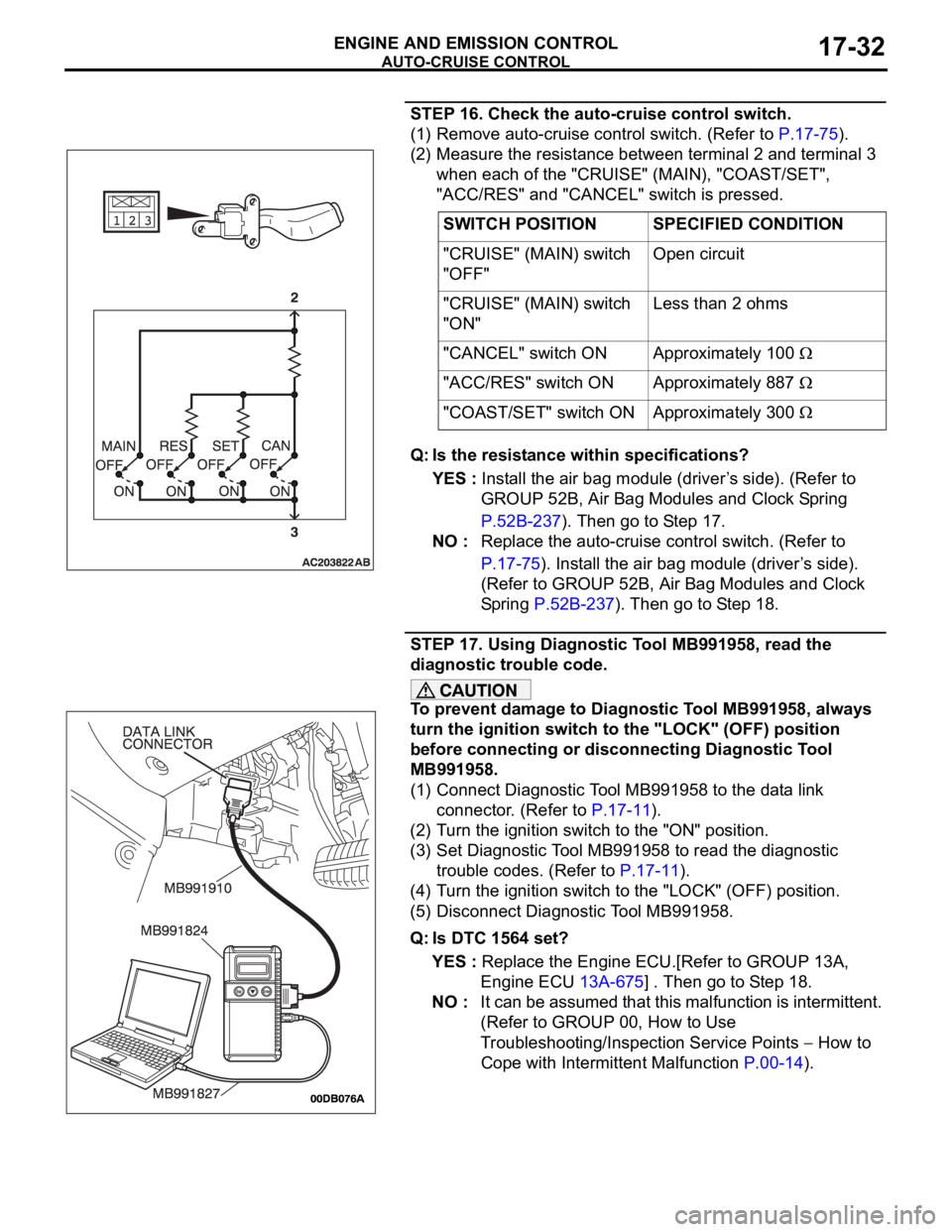
STEP 16. Check the auto-cruise control switch.
(1) Remove auto-cruise control switch. (Refer to P.17-75).
(2) Measure the resistance between terminal 2 and terminal 3
when each of the "CRUISE" (MAIN), "COAST/SET",
"ACC/RES" and "CANCEL" switch is pressed.
Q: Is the resistance within specifications?
YES : Install the air bag module (driver’s side). (Refer to
GROUP 52B, Air Bag Modules and Clock Spring
P.52B-237). Then go to Step 17.
NO : Replace the auto-cruise control switch. (Refer to
P.17-75). Install the air bag module (driver’s side).
(Refer to GROUP 52B, Air Bag Modules and Clock
Spring P.52B-237). Then go to Step 18.
STEP 17. Using Diagnostic Tool MB991958, read the
diagnostic trouble code.
To prevent damage to Diagnostic Tool MB991958, always
turn the ignition switch to the "LOCK" (OFF) position
before connecting or disconnecting Diagnostic Tool
MB991958.
(1) Connect Diagnostic Tool MB991958 to the data link
connector. (Refer to P.17-11).
(2) Turn the ignition switch to the "ON" position.
(3) Set Diagnostic Tool MB991958 to read the diagnostic
trouble codes. (Refer to P.17-11).
(4) Turn the ignition switch to the "LOCK" (OFF) position.
(5) Disconnect Diagnostic Tool MB991958.
Q: Is DTC 1564 set?
YES : Replace the Engine ECU.[Refer to GROUP 13A,
Engine ECU 13A-675] . Then go to Step 18.
NO : It can be assumed that this malfunction is intermittent.
(Refer to GROUP 00, How to Use
Troubleshooting/Inspection Service Points
How to
Cope with Intermittent Malfunction P.00-14). SWITCH POSITION SPECIFIED CONDITION
"CRUISE" (MAIN) switch
"OFF"Open circuit
"CRUISE" (MAIN) switch
"ON"Less than 2 ohms
"CANCEL" switch ON Approximately 100
"ACC/RES" switch ON Approximately 887
"COAST/SET" switch ON Approximately 300
Page 1376 of 1500
AUTO-CRUISE CONTROL
ENGINE AND EMISSION CONTROL17-45
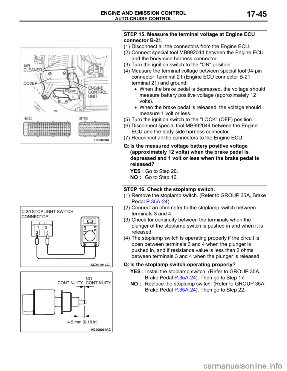
STEP 15. Measure the terminal voltage at Engine ECU
connector B-21.
(1) Disconnect all the connectors from the Engine ECU.
(2) Connect special tool MB992044 between the Engine ECU
and the body-side harness connector.
(3) Turn the ignition switch to the "ON" position.
(4) Measure the terminal voltage between special tool 94-pin
connector terminal 21 (Engine ECU connector B-21
terminal 21) and ground.
When the brake pedal is depressed, the voltage should
measure battery positive voltage (approximately 12
volts).
When the brake pedal is released, the voltage should
measure 1 volt or less.
(5) Turn the ignition switch to the "LOCK" (OFF) position.
(6) Disconnect special tool MB992044 between the Engine
ECU and the body-side harness connector.
(7) Reconnect all the connectors to the Engine ECU.
Q: Is the measured voltage battery positive voltage
(approximately 12 volts) when the brake pedal is
depressed and 1 volt or less when the brake pedal is
released?
YES : Go to Step 20.
NO : Go to Step 16.
STEP 16. Check the stoplamp switch.
(1) Remove the stoplamp switch. (Refer to GROUP 35A, Brake
Pedal P.35A-24).
(2) Connect an ohmmeter to the stoplamp switch between
terminals 3 and 4.
(3) Check for continuity between the terminals when the
plunger of the stoplamp switch is pushed in and when it is
released.
(4) The stoplamp switch is operating properly if the circuit is
open between terminals 3 and 4 when the plunger is
pushed in, and if resistance value is less than 2 ohms
between terminals 3 and 4 when the plunger is released.
Q: Is the stoplamp switch operating properly?
YES : Install the stoplamp switch. (Refer to GROUP 35A,
Brake Pedal P.35A-24). Then go to Step 17.
NO : Replace the stoplamp switch. (Refer to GROUP 35A,
Brake Pedal P.35A-24). Then go to Step 22.