Ignition circuit MITSUBISHI 380 2005 Owners Manual
[x] Cancel search | Manufacturer: MITSUBISHI, Model Year: 2005, Model line: 380, Model: MITSUBISHI 380 2005Pages: 1500, PDF Size: 47.87 MB
Page 755 of 1500
AUTO A/C DIAGNOSIS
HEATER, AIR CONDITIONING AND VENTILATION55-54
DTC U1073: Bus Off
If DTC U1073 is set in the A/C-ECU, diagnose the
CAN main bus line.
Whenever the ECU is replaced, ensure that the
communication circuit is normal.
.
TROUBLE JUDGMENT
DTC U1073 will be stored when the A/C-ECU ceases
CAN communication (bus off) and then resumes the
communication when the ignition switch is turned to
the "LOCK" (OFF) position.
.
TECHNICAL DESCRIPTION (COMMENT)
The wiring harness wire or connectors may have
loose, corroded, or damage terminals, or terminals
pushed back in the connector, or the A/C-ECU may
be defective.
.
TROUBLESHOOTING HINTS
Defective connector(s) or wiring harness
Malfunction of the A/C-ECU.
Refer to component locations GROUP-70
Refer to configuration diagrams GROUP-80
Refer to circuit diagrams GROUP-90
DIAGNOSIS
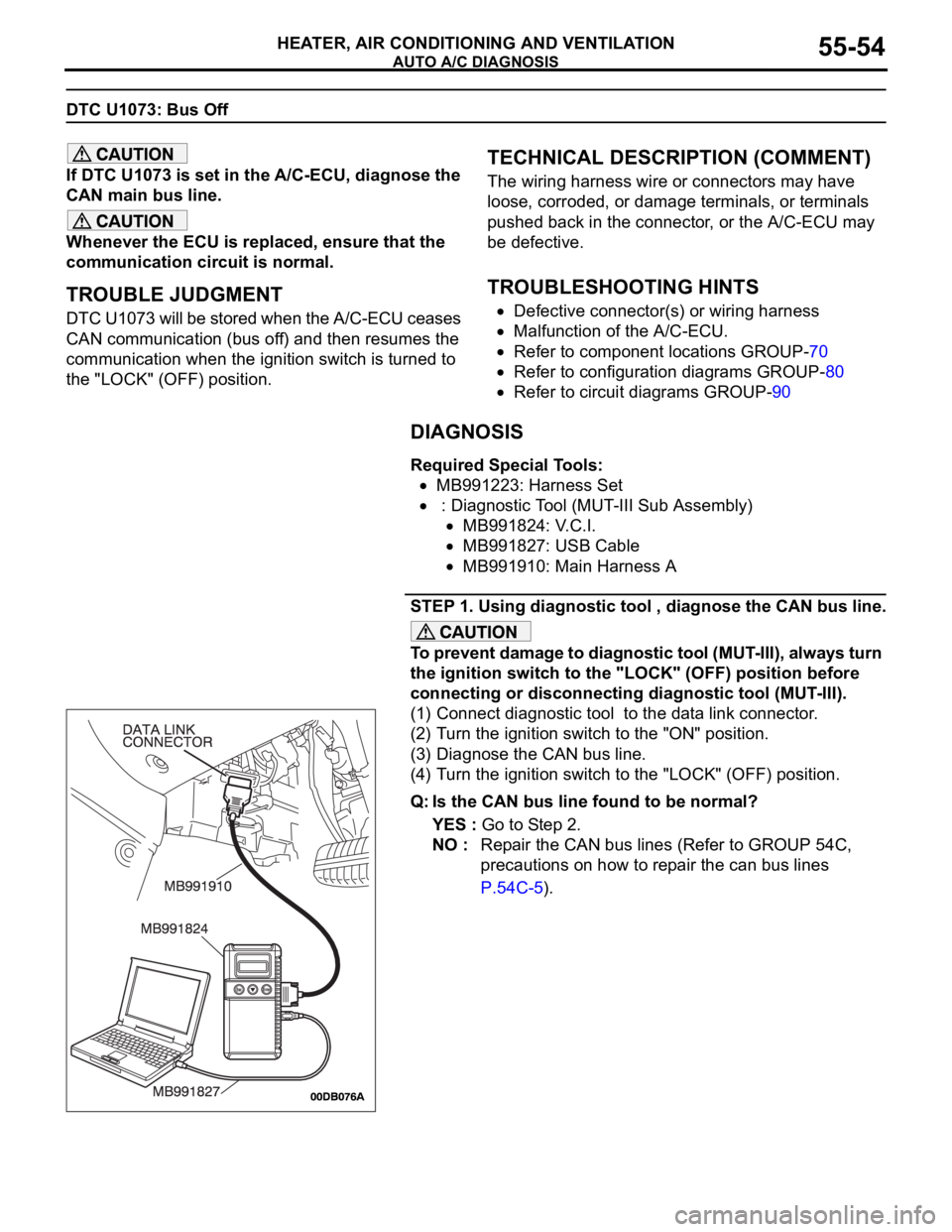
Required Special Tools:
MB991223: Harness Set
: Diagnostic Tool (MUT-III Sub Assembly)
MB991824: V.C.I.
MB991827: USB Cable
MB991910: Main Harness A
STEP 1. Using diagnostic tool , diagnose the CAN bus line.
To prevent damage to diagnostic tool (MUT-III), always turn
the ignition switch to the "LOCK" (OFF) position before
connecting or disconnecting diagnostic tool (MUT-III).
(1) Connect diagnostic tool to the data link connector.
(2) Turn the ignition switch to the "ON" position.
(3) Diagnose the CAN bus line.
(4) Turn the ignition switch to the "LOCK" (OFF) position.
Q: Is the CAN bus line found to be normal?
YES : Go to Step 2.
NO : Repair the CAN bus lines (Refer to GROUP 54C,
precautions on how to repair the can bus lines
P.54C-5).
Page 756 of 1500
AUTO A/C DIAGNOSIS
HEATER, AIR CONDITIONING AND VENTILATION55-55
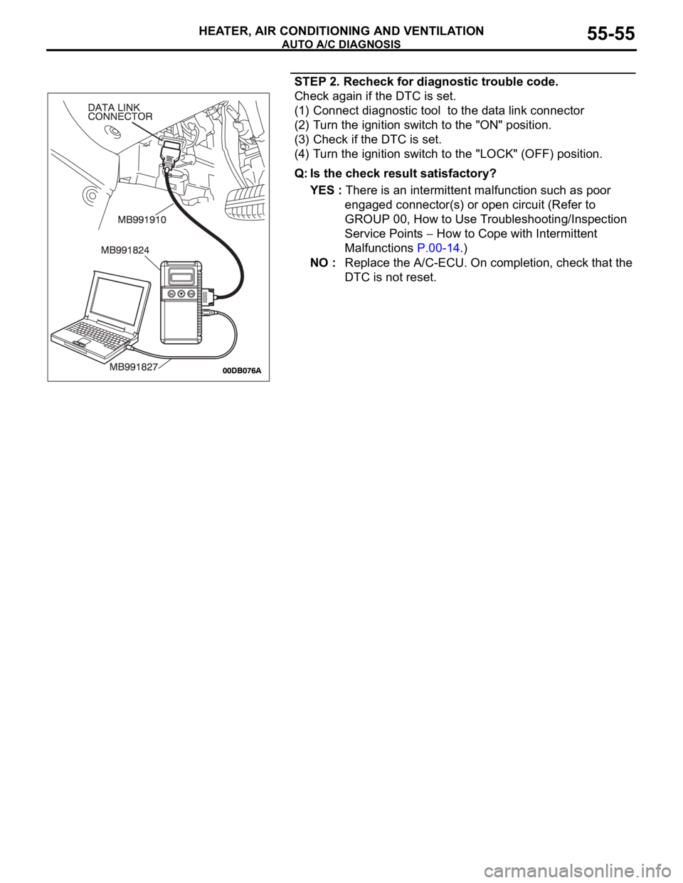
STEP 2. Recheck for diagnostic trouble code.
Check again if the DTC is set.
(1) Connect diagnostic tool to the data link connector
(2) Turn the ignition switch to the "ON" position.
(3) Check if the DTC is set.
(4) Turn the ignition switch to the "LOCK" (OFF) position.
Q: Is the check result satisfactory?
YES : There is an intermittent malfunction such as poor
engaged connector(s) or open circuit (Refer to
GROUP 00, How to Use Troubleshooting/Inspection
Service Points
How to Cope with Intermittent
Malfunctions P.00-14.)
NO : Replace the A/C-ECU. On completion, check that the
DTC is not reset.
Page 759 of 1500
AUTO A/C DIAGNOSIS
HEATER, AIR CONDITIONING AND VENTILATION55-58
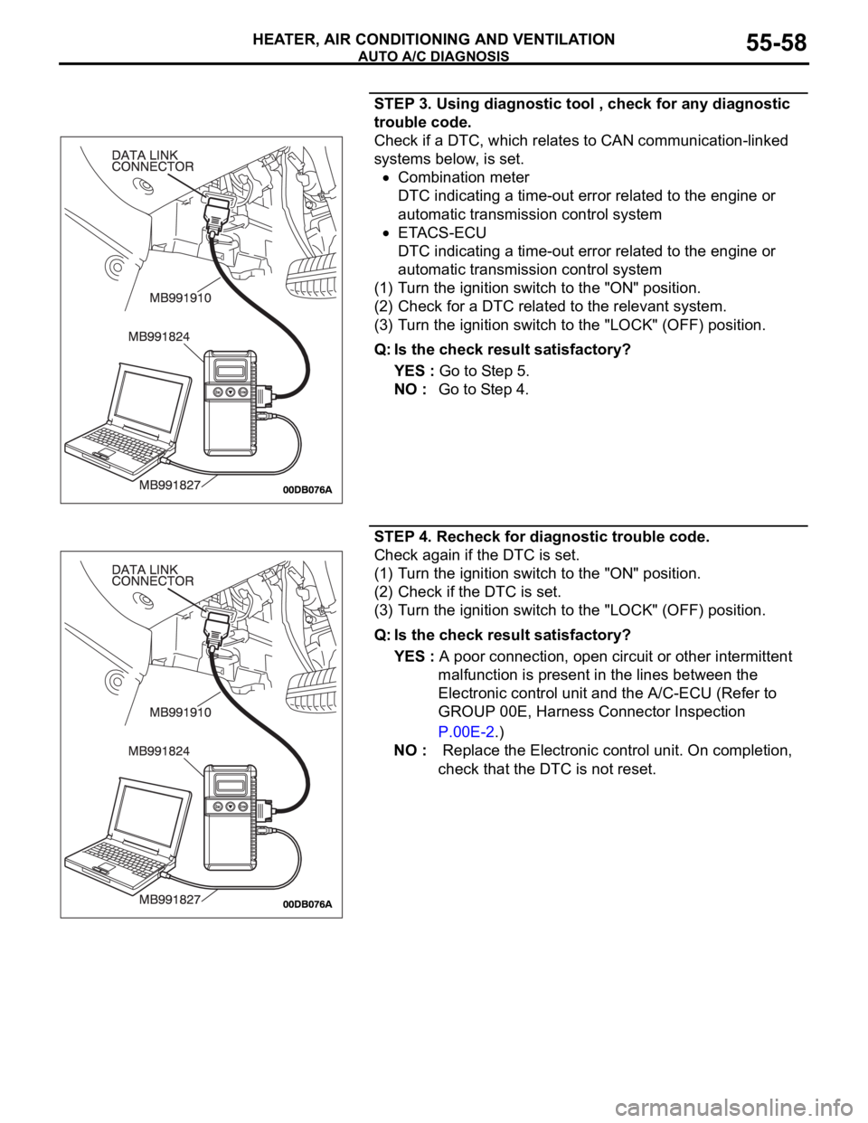
STEP 3. Using diagnostic tool , check for any diagnostic
trouble code.
Check if a DTC, which relates to CAN communication-linked
systems below, is set.
Combination meter
DTC indicating a time-out error related to the engine or
automatic transmission control system
ETACS-ECU
DTC indicating a time-out error related to the engine or
automatic transmission control system
(1) Turn the ignition switch to the "ON" position.
(2) Check for a DTC related to the relevant system.
(3) Turn the ignition switch to the "LOCK" (OFF) position.
Q: Is the check result satisfactory?
YES : Go to Step 5.
NO : Go to Step 4.
STEP 4. Recheck for diagnostic trouble code.
Check again if the DTC is set.
(1) Turn the ignition switch to the "ON" position.
(2) Check if the DTC is set.
(3) Turn the ignition switch to the "LOCK" (OFF) position.
Q: Is the check result satisfactory?
YES : A poor connection, open circuit or other intermittent
malfunction is present in the lines between the
Electronic control unit and the A/C-ECU (Refer to
GROUP 00E, Harness Connector Inspection
P.00E-2.)
NO : Replace the Electronic control unit. On completion,
check that the DTC is not reset.
Page 760 of 1500
AUTO A/C DIAGNOSIS
HEATER, AIR CONDITIONING AND VENTILATION55-59
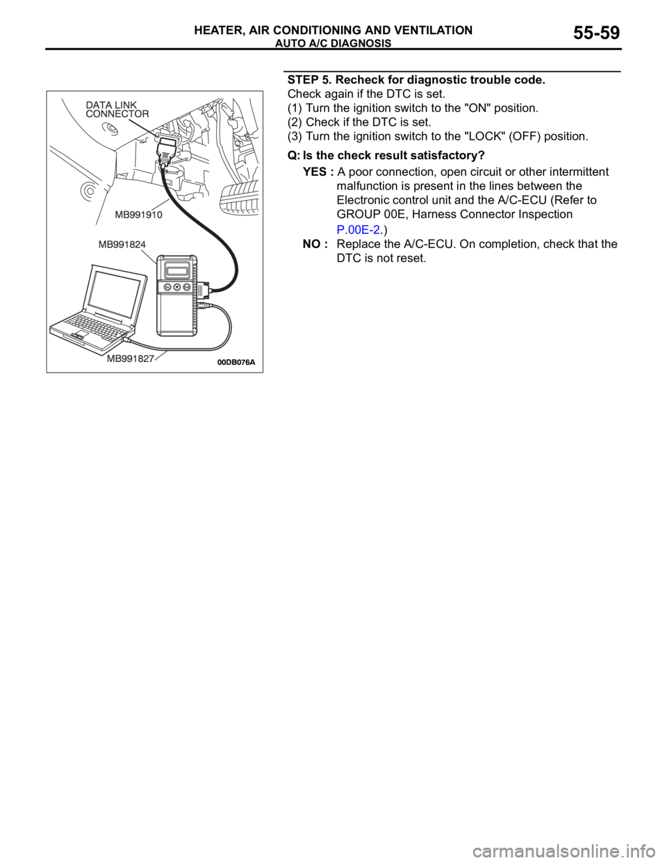
STEP 5. Recheck for diagnostic trouble code.
Check again if the DTC is set.
(1) Turn the ignition switch to the "ON" position.
(2) Check if the DTC is set.
(3) Turn the ignition switch to the "LOCK" (OFF) position.
Q: Is the check result satisfactory?
YES : A poor connection, open circuit or other intermittent
malfunction is present in the lines between the
Electronic control unit and the A/C-ECU (Refer to
GROUP 00E, Harness Connector Inspection
P.00E-2.)
NO : Replace the A/C-ECU. On completion, check that the
DTC is not reset.
Page 763 of 1500
AUTO A/C DIAGNOSIS
HEATER, AIR CONDITIONING AND VENTILATION55-62
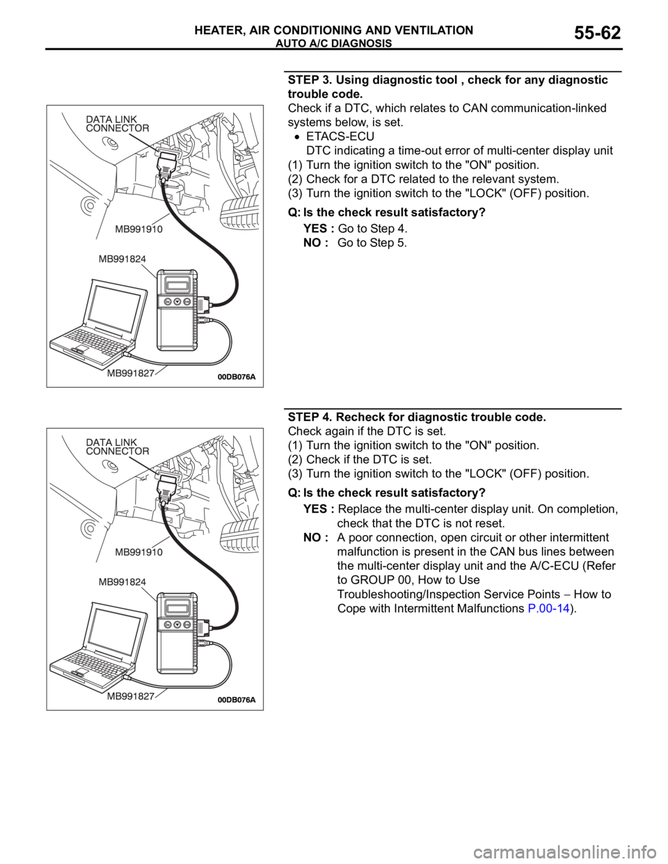
STEP 3. Using diagnostic tool , check for any diagnostic
trouble code.
Check if a DTC, which relates to CAN communication-linked
systems below, is set.
ETACS-ECU
DTC indicating a time-out error of multi-center display unit
(1) Turn the ignition switch to the "ON" position.
(2) Check for a DTC related to the relevant system.
(3) Turn the ignition switch to the "LOCK" (OFF) position.
Q: Is the check result satisfactory?
YES : Go to Step 4.
NO : Go to Step 5.
STEP 4. Recheck for diagnostic trouble code.
Check again if the DTC is set.
(1) Turn the ignition switch to the "ON" position.
(2) Check if the DTC is set.
(3) Turn the ignition switch to the "LOCK" (OFF) position.
Q: Is the check result satisfactory?
YES : Replace the multi-center display unit. On completion,
check that the DTC is not reset.
NO : A poor connection, open circuit or other intermittent
malfunction is present in the CAN bus lines between
the multi-center display unit and the A/C-ECU (Refer
to GROUP 00, How to Use
Troubleshooting/Inspection Service Points
How to
Cope with Intermittent Malfunctions P.00-14).
Page 764 of 1500
AUTO A/C DIAGNOSIS
HEATER, AIR CONDITIONING AND VENTILATION55-63
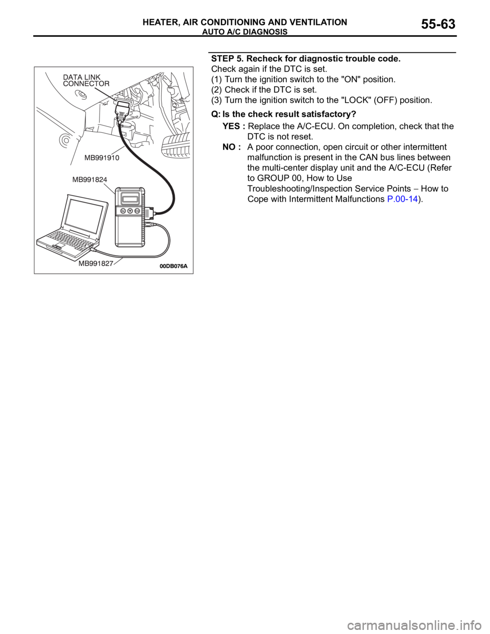
STEP 5. Recheck for diagnostic trouble code.
Check again if the DTC is set.
(1) Turn the ignition switch to the "ON" position.
(2) Check if the DTC is set.
(3) Turn the ignition switch to the "LOCK" (OFF) position.
Q: Is the check result satisfactory?
YES : Replace the A/C-ECU. On completion, check that the
DTC is not reset.
NO : A poor connection, open circuit or other intermittent
malfunction is present in the CAN bus lines between
the multi-center display unit and the A/C-ECU (Refer
to GROUP 00, How to Use
Troubleshooting/Inspection Service Points
How to
Cope with Intermittent Malfunctions P.00-14).
Page 767 of 1500
AUTO A/C DIAGNOSIS
HEATER, AIR CONDITIONING AND VENTILATION55-66
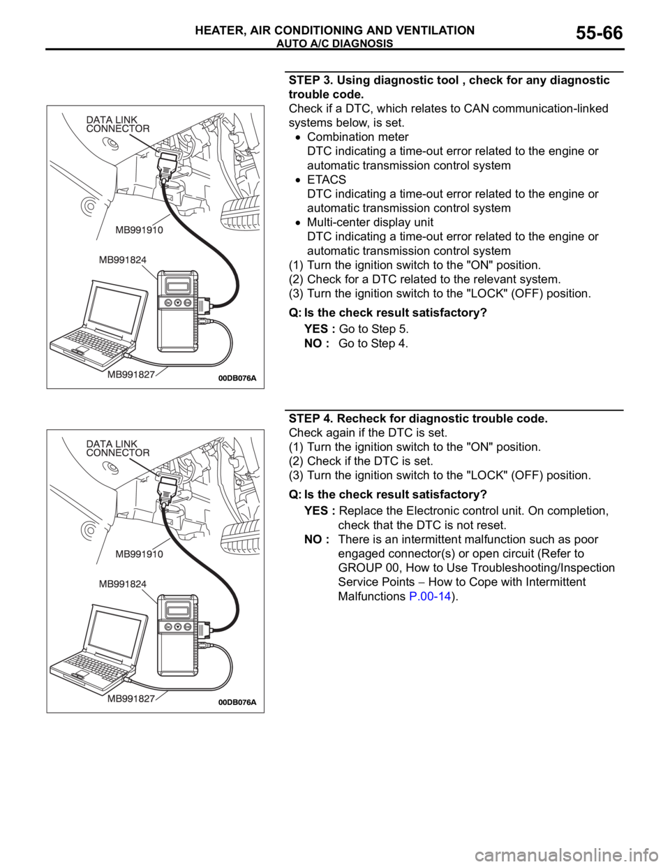
STEP 3. Using diagnostic tool , check for any diagnostic
trouble code.
Check if a DTC, which relates to CAN communication-linked
systems below, is set.
Combination meter
DTC indicating a time-out error related to the engine or
automatic transmission control system
ETACS
DTC indicating a time-out error related to the engine or
automatic transmission control system
Multi-center display unit
DTC indicating a time-out error related to the engine or
automatic transmission control system
(1) Turn the ignition switch to the "ON" position.
(2) Check for a DTC related to the relevant system.
(3) Turn the ignition switch to the "LOCK" (OFF) position.
Q: Is the check result satisfactory?
YES : Go to Step 5.
NO : Go to Step 4.
STEP 4. Recheck for diagnostic trouble code.
Check again if the DTC is set.
(1) Turn the ignition switch to the "ON" position.
(2) Check if the DTC is set.
(3) Turn the ignition switch to the "LOCK" (OFF) position.
Q: Is the check result satisfactory?
YES : Replace the Electronic control unit. On completion,
check that the DTC is not reset.
NO : There is an intermittent malfunction such as poor
engaged connector(s) or open circuit (Refer to
GROUP 00, How to Use Troubleshooting/Inspection
Service Points
How to Cope with Intermittent
Malfunctions P.00-14).
Page 768 of 1500
AUTO A/C DIAGNOSIS
HEATER, AIR CONDITIONING AND VENTILATION55-67
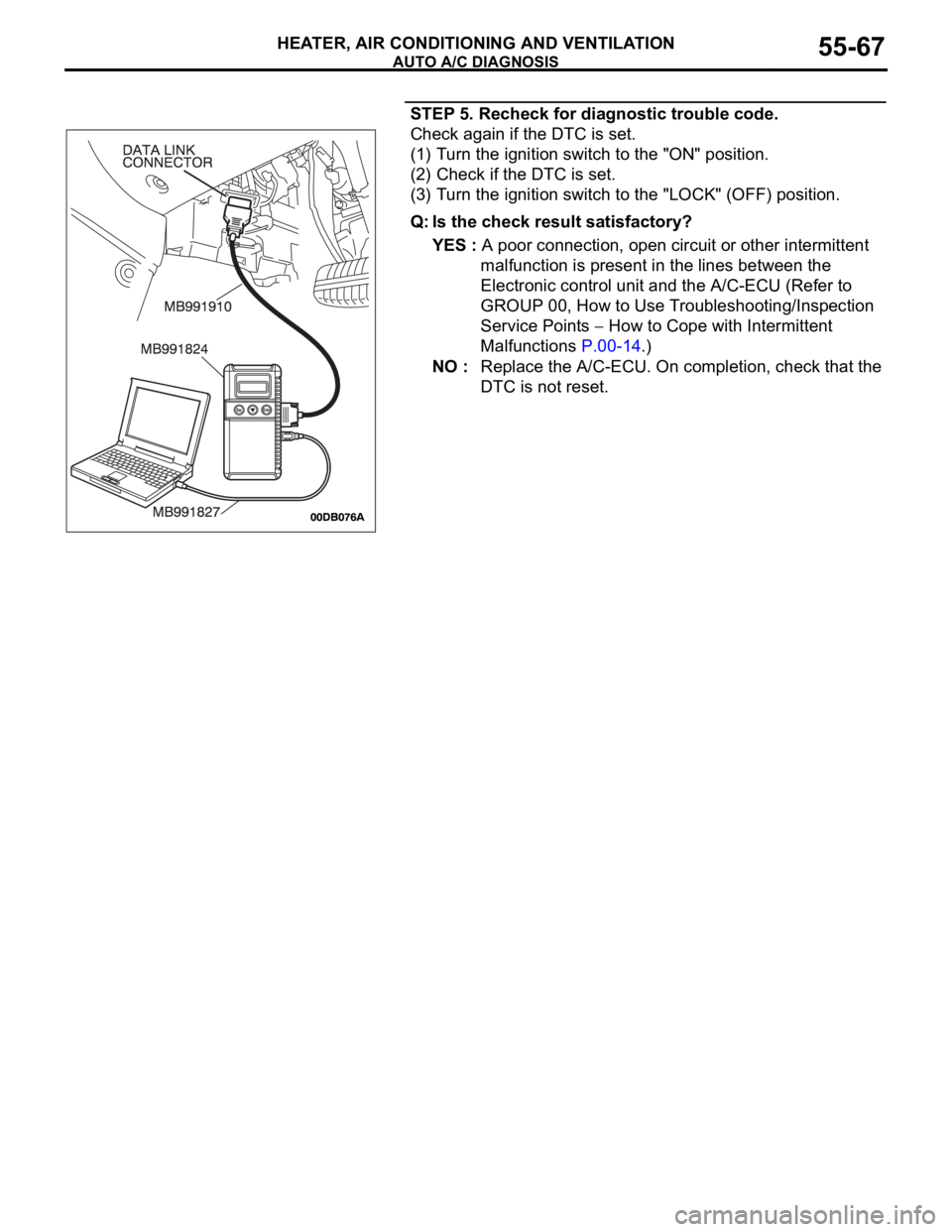
STEP 5. Recheck for diagnostic trouble code.
Check again if the DTC is set.
(1) Turn the ignition switch to the "ON" position.
(2) Check if the DTC is set.
(3) Turn the ignition switch to the "LOCK" (OFF) position.
Q: Is the check result satisfactory?
YES : A poor connection, open circuit or other intermittent
malfunction is present in the lines between the
Electronic control unit and the A/C-ECU (Refer to
GROUP 00, How to Use Troubleshooting/Inspection
Service Points
How to Cope with Intermittent
Malfunctions P.00-14.)
NO : Replace the A/C-ECU. On completion, check that the
DTC is not reset.
Page 770 of 1500
AUTO A/C DIAGNOSIS
HEATER, AIR CONDITIONING AND VENTILATION55-69
SYMPTOM PROCEDURES
INSPECTION PROCEDURE 1: When the Ignition Switch is "ON", the A/C does not Operate.
.
TECHNICAL DESCRIPTION (COMMENT)
The blower system or the compressor system may
be defective if there is no cool air coming from the
vents.
.
TROUBLESHOOTING HINTS
Malfunction of blower motor
Malfunction of A/C compressor
Refer to component locations GROUP-70
Refer to configuration diagrams GROUP-80
Refer to circuit diagrams GROUP-90
DIAGNOSIS
Check that the blower motor operation when the blower
switch is moved to the "HI" position.
(1) Turn the ignition switch to the "ON" position.
(2) Turn the blower speed selection dial to the blower operating
position.
Q: Does the blower motor operate when the speed
selection dial is turned to the blower operating
position?
YES : Refer to Inspection procedure 4 "When the A/C is
operating, temperature inside the passenger
compartment does not decrease (cool air not emitted)
P.55-75."
NO : Refer to Inspection procedure 5 "Blower fan and
motor do not turn P.55-89."
INSPECTION PROCEDURE 2: When the Air Outlet Changeover Control Knob is Moved to
DEFROSTER or DEFROSTER/FOOT Position, the A/C or the Inside/outside Air Changeover Damper
Motor does not operate.
.
TECHNICAL DESCRIPTION (COMMENT)
If the outside/inside air selection damper control
motor does not operate normally, the inside/outside
air changeover damper motor system may be defec-
tive.
.
TROUBLESHOOTING HINTS
Malfunction of the A/C-ECU
Malfunction of the outside/inside air selection
damper control motor
Damaged harness wires or connectors
Refer to component locations GROUP-70
Refer to configuration diagrams GROUP-80
Refer to circuit diagrams GROUP-90
Page 771 of 1500
AUTO A/C DIAGNOSIS
HEATER, AIR CONDITIONING AND VENTILATION55-70
DIAGNOSIS
Check operation of the outside/inside air selection damper
control motor.
(1) Turn the ignition switch to the "ON" position.
(2) Outside/inside air selection damper motor switch: This is
used to switch from the inside air to outside air or vice
versa.
(3) Check to see that the outside/inside air selection damper
motor operates normally.
Q: Does outside/inside air selection damper control motor
work normally?
YES : Replace the A/C-ECU.
NO : Refer to Inspection procedure 3, "Inside/outside air
changeover is not possible P.55-70."
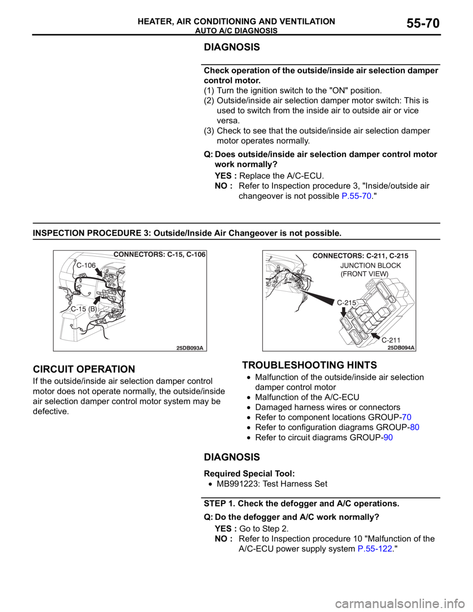
INSPECTION PROCEDURE 3: Outside/Inside Air Changeover is not possible.
.
CIRCUIT OPERATION
If the outside/inside air selection damper control
motor does not operate normally, the outside/inside
air selection damper control motor system may be
defective.
.
TROUBLESHOOTING HINTS
Malfunction of the outside/inside air selection
damper control motor
Malfunction of the A/C-ECU
Damaged harness wires or connectors
Refer to component locations GROUP-70
Refer to configuration diagrams GROUP-80
Refer to circuit diagrams GROUP-90
DIAGNOSIS
Required Special Tool:
MB991223: Test Harness Set
STEP 1. Check the defogger and A/C operations.
Q: Do the defogger and A/C work normally?
YES : Go to Step 2.
NO : Refer to Inspection procedure 10 "Malfunction of the
A/C-ECU power supply system P.55-122."