MITSUBISHI 380 2005 Workshop Manual
380 2005
MITSUBISHI
MITSUBISHI
https://www.carmanualsonline.info/img/19/57086/w960_57086-0.png
MITSUBISHI 380 2005 Workshop Manual
Trending: jump start, navigation, oil temperature, engine, recommended oil, battery location, auto transmission
Page 1451 of 1500
SPECIAL TOOLS
REAR AXLE27-4
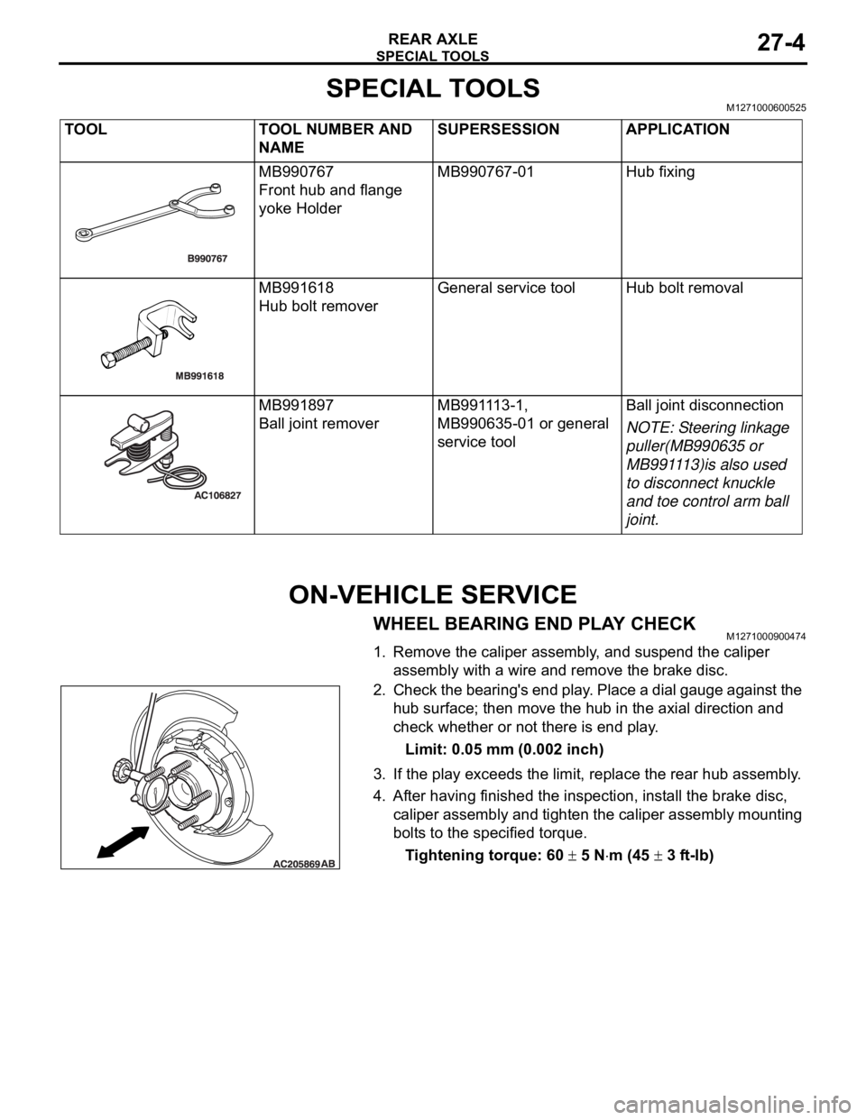
SPECIAL TOOLSM1271000600525
ON-VEHICLE SERVICE
WHEEL BEARING END PLAY CHECKM1271000900474
1. Remove the caliper assembly, and suspend the caliper
assembly with a wire and remove the brake disc.
2. Check the bearing's end play. Place a dial gauge against the
hub surface; then move the hub in the axial direction and
check whether or not there is end play.
Limit: 0.05 mm (0.002 inch)
3. If the play exceeds the limit, replace the rear hub assembly.
4. After having finished the inspection, install the brake disc,
caliper assembly and tighten the caliper assembly mounting
bolts to the specified torque.
Tightening torque: 60
5 Nm (45 3 ft-lb) TOOL TOOL NUMBER AND
NAMESUPERSESSION APPLICATION
MB990767
Front hub and flange
yoke HolderMB990767-01 Hub fixing
MB991618
Hub bolt removerGeneral service tool Hub bolt removal
MB991897
Ball joint removerMB991113-1,
MB990635-01 or general
service toolBall joint disconnection
NOTE: Steering linkage
puller(MB990635 or
MB991113)is also used
to disconnect knuckle
and toe control arm ball
joint.
Page 1452 of 1500
ON-VEHICLE SERVICE
REAR AXLE27-5
REAR HUB ROTARY-SLIDING RESISTANCE
CHECK
M1271001100266
1. Remove the caliper assembly, and suspend the caliper
assembly with a wire and remove the brake disc.
2. Turn the hub a few times to seat the bearing.
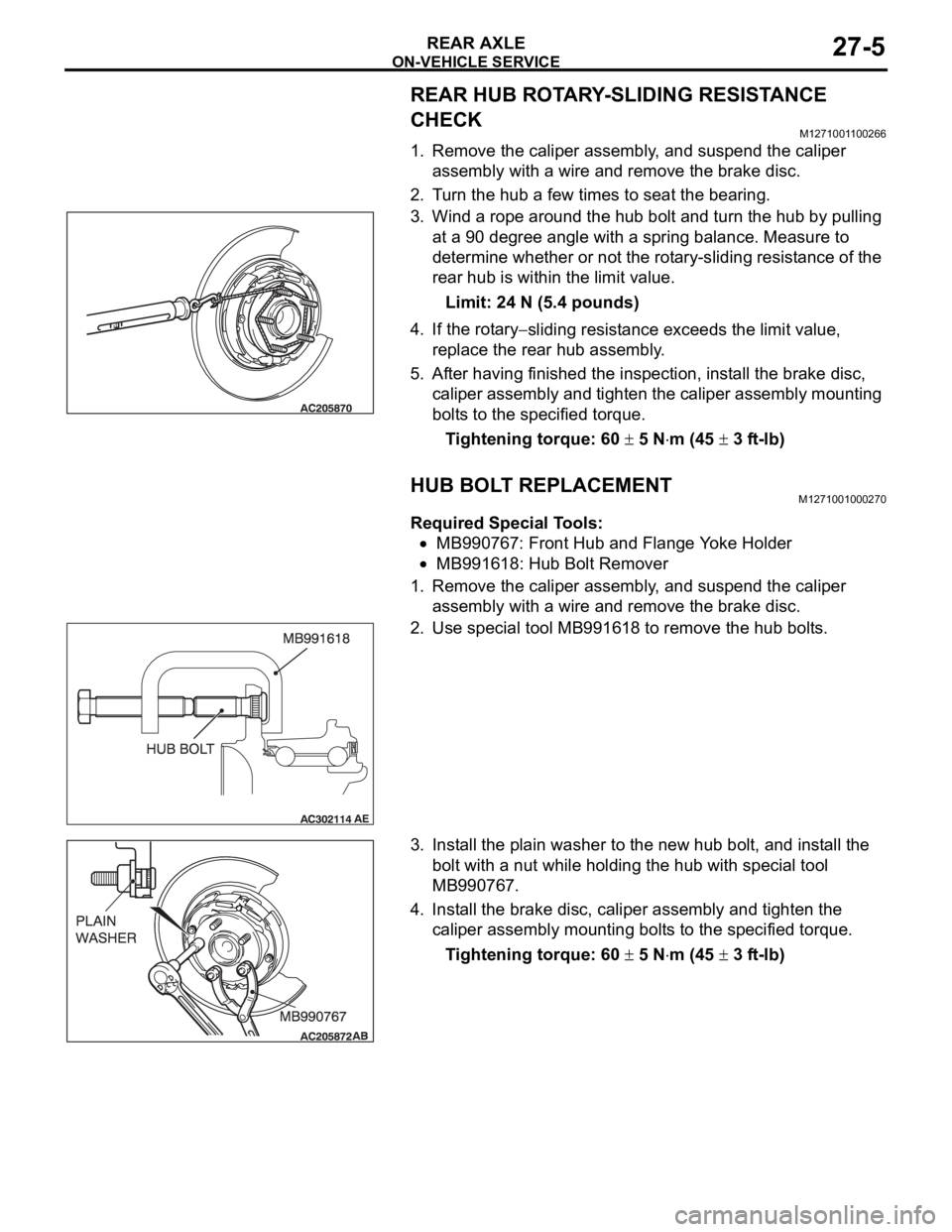
3. Wind a rope around the hub bolt and turn the hub by pulling
at a 90 degree angle with a spring balance. Measure to
determine whether or not the rotary-sliding resistance of the
rear hub is within the limit value.
Limit: 24 N (5.4 pounds)
4. If the rotary
sliding resistance exceeds the limit value,
replace the rear hub assembly.
5. After having finished the inspection, install the brake disc,
caliper assembly and tighten the caliper assembly mounting
bolts to the specified torque.
Tightening torque: 60
5 Nm (45 3 ft-lb)
HUB BOLT REPLACEMENTM1271001000270
Required Special Tools:
MB990767: Front Hub and Flange Yoke Holder
MB991618: Hub Bolt Remover
1. Remove the caliper assembly, and suspend the caliper
assembly with a wire and remove the brake disc.
2. Use special tool MB991618 to remove the hub bolts.
3. Install the plain washer to the new hub bolt, and install the
bolt with a nut while holding the hub with special tool
MB990767.
4. Install the brake disc, caliper assembly and tighten the
caliper assembly mounting bolts to the specified torque.
Tightening torque: 60
5 Nm (45 3 ft-lb)
Page 1453 of 1500
Page 1454 of 1500
REAR AXLE HUB ASSEMBLY
REAR AXLE27-7
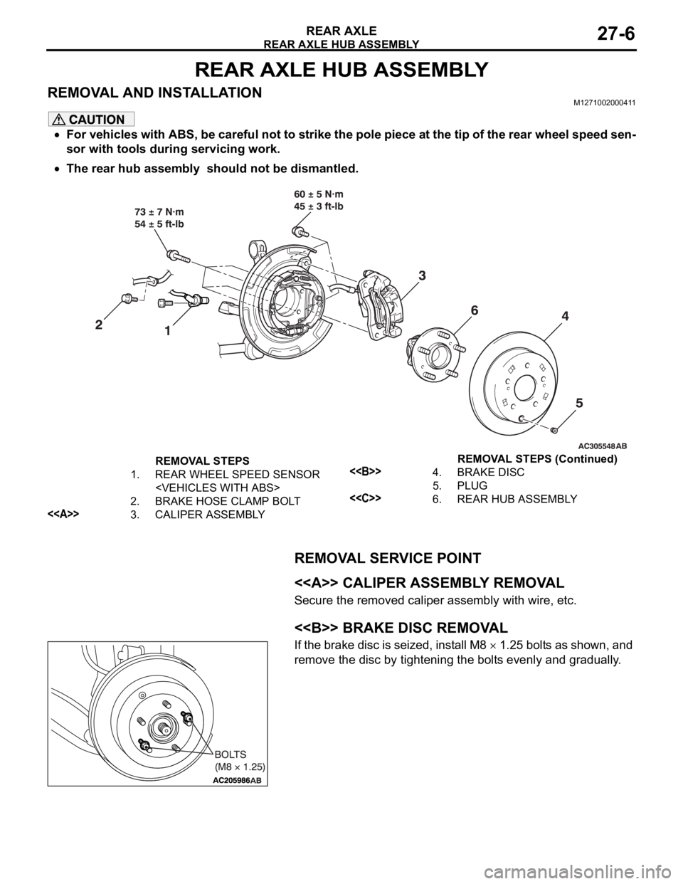
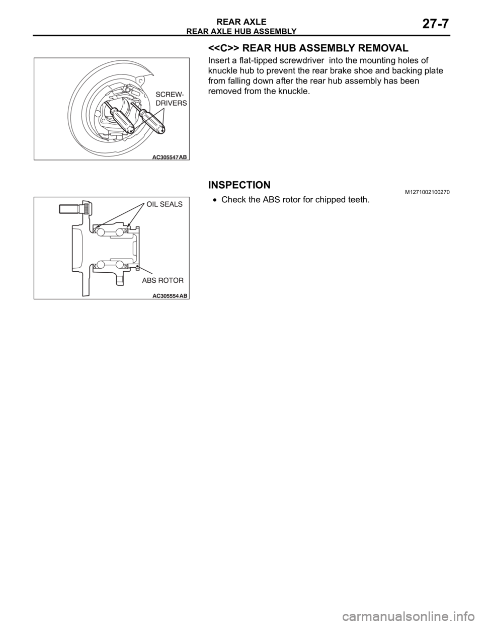
<> REAR HUB ASSEMBLY REMOVAL
Insert a flat-tipped screwdriver into the mounting holes of
knuckle hub to prevent the rear brake shoe and backing plate
from falling down after the rear hub assembly has been
removed from the knuckle.
INSPECTIONM1271002100270
Check the ABS rotor for chipped teeth.
Page 1455 of 1500
Page 1456 of 1500
Page 1457 of 1500
SPECIFICATIONS
REAR AXLE27-10
SPECIFICATIONS
FASTENER TIGHTENING SPECIFICATIONSM1271004000332
SERVICE SPECIFICATIONSM1271000300502
ITEM SPECIFICATION
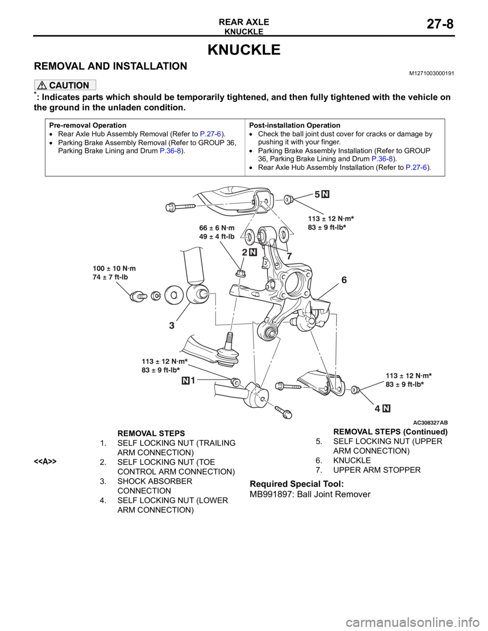
Knuckle Lower arm assembly to knuckle nut 113
12 Nm (83 9 ft-lb)
Shock absorber assembly to knuckle
bolt100
10 Nm (74 7 ft-lb)
Self locking nut (toe control arm
connection)66
6 Nm (49 4 ft-lb)
Trailing arm assembly to knuckle nut 113
12 Nm (83 9 ft-lb)
Upper arm assembly to knuckle nut 113
12 Nm (83 9 ft-lb)
Rear axle hub assembly Brake caliper assembly bolt 60
5 Nm (45 3 ft-lb)
Rear hub assembly bolt 73
7 Nm (54 5 ft-lb)
ITEM LIMIT
Wheel bearing end play mm (in) 0.05 (0.002)
Rear hub rotary-sliding resistance N (lb) 24 (5.4)
Page 1458 of 1500
23-1
GROUP 23
AUTOMATIC
TRANSAXLE
CONTENTS
AUTOMATIC TRANSAXLE . . . . . . . . . . . . . . . . . . . . . . . . . . . .23A
AUTOMATIC TRANSAXLE OVERHAUL. . . . . . . . . . . . . . . . . .23B
Page 1459 of 1500
Page 1460 of 1500
23A-1
GROUP 23A
AUTOMATIC
TRANSMISSION
CONTENTS
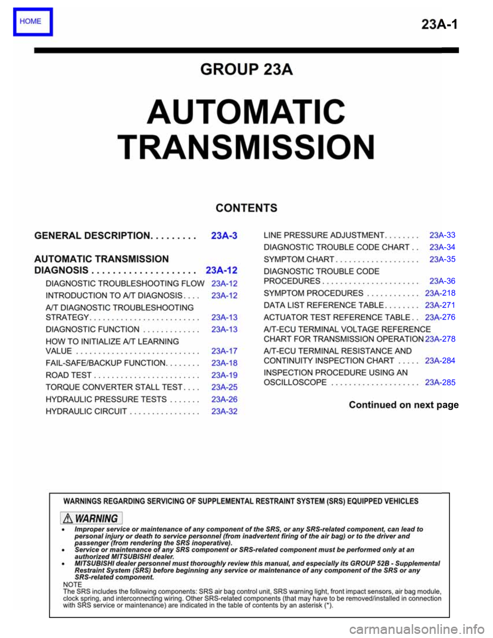
GENERAL DESCRIPTION. . . . . . . . .23A-3
AUTOMATIC TRANSMISSION
DIAGNOSIS . . . . . . . . . . . . . . . . . . . .23A-12
DIAGNOSTIC TROUBLESHOOTING FLOW23A-12
INTRODUCTION TO A/T DIAGNOSIS . . . . 23A-12
A/T DIAGNOSTIC TROUBLESHOOTING
STRATEGY . . . . . . . . . . . . . . . . . . . . . . . . . 23A-13
DIAGNOSTIC FUNCTION . . . . . . . . . . . . . 23A-13
HOW TO INITIALIZE A/T LEARNING
VALUE . . . . . . . . . . . . . . . . . . . . . . . . . . . . 23A-17
FAIL-SAFE/BACKUP FUNCTION. . . . . . . . 23A-18
ROAD TEST . . . . . . . . . . . . . . . . . . . . . . . . 23A-19
TORQUE CONVERTER STALL TEST . . . . 23A-25
HYDRAULIC PRESSURE TESTS . . . . . . . 23A-26
HYDRAULIC CIRCUIT . . . . . . . . . . . . . . . . 23A-32LINE PRESSURE ADJUSTMENT . . . . . . . . 23A-33
DIAGNOSTIC TROUBLE CODE CHART . . 23A-34
SYMPTOM CHART . . . . . . . . . . . . . . . . . . . 23A-35
DIAGNOSTIC TROUBLE CODE
PROCEDURES . . . . . . . . . . . . . . . . . . . . . . 23A-36
SYMPTOM PROCEDURES . . . . . . . . . . . . 23A-218
DATA LIST REFERENCE TABLE . . . . . . . . 23A-271
ACTUATOR TEST REFERENCE TABLE . . 23A-276
A/T-ECU TERMINAL VOLTAGE REFERENCE
CHART FOR TRANSMISSION OPERATION23A-278
A/T-ECU TERMINAL RESISTANCE AND
CONTINUITY INSPECTION CHART . . . . . 23A-284
INSPECTION PROCEDURE USING AN
OSCILLOSCOPE . . . . . . . . . . . . . . . . . . . . 23A-285
Continued on next page
WARNINGS REGARDING SERVICING OF SUPPLEMENTAL RESTRAINT SYSTEM (SRS) EQUIPPED VEHICLES
Trending: door lock, Transmitter, wheel alignment, Interior light, Fuel pump wiring, Relay box, lock


