engine MITSUBISHI 380 2005 Workshop Manual
[x] Cancel search | Manufacturer: MITSUBISHI, Model Year: 2005, Model line: 380, Model: MITSUBISHI 380 2005Pages: 1500, PDF Size: 47.87 MB
Page 1239 of 1500
VEHICLE IDENTIFICATION
GENERAL00-18
VEHICLE IDENTIFICATION
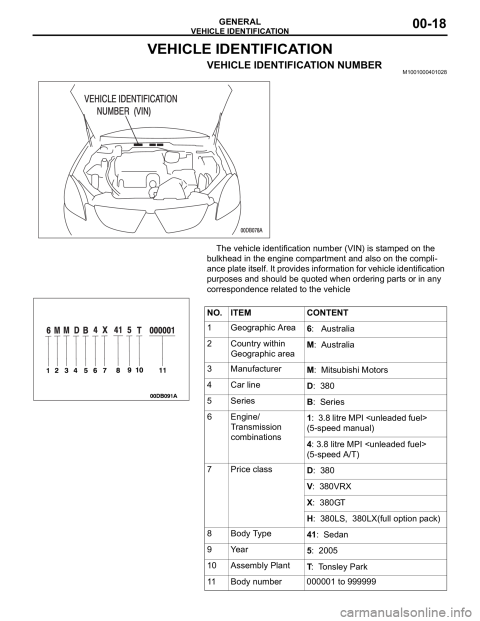
VEHICLE IDENTIFICATION NUMBERM1001000401028
The vehicle identification number (VIN) is stamped on the
bulkhead in the engine compartment and also on the compli-
ance plate itself. It provides information for vehicle identification
purposes and should be quoted when ordering parts or in any
correspondence related to the vehicle
NO. ITEM CONTENT
1 Geographic Area
6: Australia
2 Country within
Geographic areaM: Australia
3 Manufacturer
M: Mitsubishi Motors
4 Car line
D: 380
5Series
B: Series
6 Engine/
Transmission
combinations1: 3.8 litre MPI
(5-speed manual)
4: 3.8 litre MPI
(5-speed A/T)
7Price class
D: 380
V: 380VRX
X: 380GT
H: 380LS, 380LX(full option pack)
8 Body Type
41: Sedan
9Year
5: 2005
10 Assembly Plant
T: Tonsley Park
11 Body number 000001 to 999999
Page 1240 of 1500
VEHICLE IDENTIFICATION
GENERAL00-19
VEHICLE INFORMATION NUMBER LIST
NOTE: ** = Becomes 380LX as a full option pack.
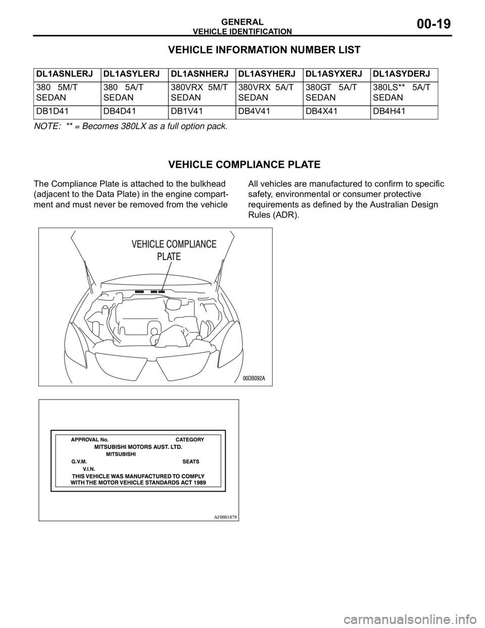
VEHICLE COMPLIANCE PLATE
The Compliance Plate is attached to the bulkhead
(adjacent to the Data Plate) in the engine compart-
ment and must never be removed from the vehicle All vehicles are manufactured to confirm to specific
safety, environmental or consumer protective
requirements as defined by the Australian Design
Rules (ADR). DL1ASNLERJ DL1ASYLERJ DL1ASNHERJ DL1ASYHERJ DL1ASYXERJ DL1ASYDERJ
380 5M/T
SEDAN380 5A/T
SEDAN380VRX 5M/T
SEDAN380VRX 5A/T
SEDAN380GT 5A/T
SEDAN380LS** 5A/T
SEDAN
DB1D41 DB4D41 DB1V41 DB4V41 DB4X41 DB4H41
Page 1241 of 1500

VEHICLE IDENTIFICATION
GENERAL00-20
VEHICLE DATA PLATEM1001005400707
The vehicle data plate is attached on the bulk-
head, between the vehicle identification number (VIN) and the
compliance plate at the top outer panel in the engine compart-
ment.
The plate shows vehicle option codes, trim codes and a daily
body sequential build number.
AUSTRALIAN DESIGN RULES
Australian Design Rules require the manufacturer of components and/ or a complete vehicle to conform to
specific safety, environmental or consumer protective requirements as defined by that particular rule. There is
legislation that requires, amongst other things that no modifications be made to a vehicle that would cause
that vehicle not to comply with the Design Rules of that vehicle (parts replacement using approved Mitsubishi
Motors Australia Limited components is permissible). Before interchanging or adding optional equipment or
using non-Genuine Parts, it is recommended that advice be sought from an Authorised Mitsubishi Motors
Australia Limited Dealer or from a Mitsubishi Motors Australia Limited Regional Office, because it is possible
to inadvertently cause a vehicle not to comply with a Design Rule.
Page 1243 of 1500
PRECAUTIONS BEFORE SERVICE
GENERAL00-22
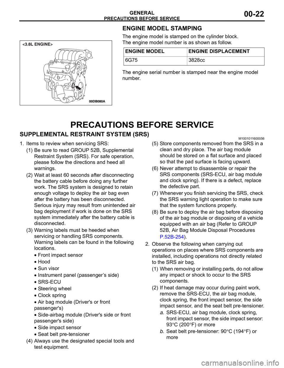
ENGINE MODEL STAMPING
The engine model is stamped on the cylinder block.
The engine model number is as shown as follow.
The engine serial number is stamped near the engine model
number.
PRECAUTIONS BEFORE SERVICE
SUPPLEMENTAL RESTRAINT SYSTEM (SRS)M1001011600056
1. Items to review when servicing SRS:
(1) Be sure to read GROUP 52B, Supplemental
Restraint System (SRS). For safe operation,
please follow the directions and heed all
warnings.
(2) Wait at least 60 seconds after disconnecting
the battery cable before doing any further
work. The SRS system is designed to retain
enough voltage to deploy the air bag even
after the battery has been disconnected.
Serious injury may result from unintended air
bag deployment if work is done on the SRS
system immediately after the battery cable is
disconnected.
(3) Warning labels must be heeded when
servicing or handling SRS components.
Warning labels can be found in the following
locations.
Front impact sensor
Hood
Sun visor
Instrument panel (passenger ’s side)
SRS-ECU
Steering wheel
Clock spring
Air bag module (Driver's or front
passenger's)
Side-airbag module (Driver's side or front
passenger's side)
Side impact sensor
Seat belt pre-tensioner
(4) Always use the designated special tools and
test equipment.(5) Store components removed from the SRS in a
clean and dry place. The air bag module
should be stored on a flat surface and placed
so that the pad surface is facing upward.
(6) Never attempt to disassemble or repair the
SRS components (SRS-ECU, air bag module
and clock spring). If there is a defect, replace
the defective part.
(7) Whenever you finish servicing the SRS, check
the SRS warning light operation to make sure
that the system functions properly.
(8) Be sure to deploy the air bag before disposing
of the air bag module or disposing of a vehicle
equipped with an air bag (Refer to GROUP
52B, Air Bag Module Disposal Procedures
P.52B-254).
2. Observe the following when carrying out
operations on places where SRS components are
installed, including operations not directly related
to the SRS air bag.
(1) When removing or installing parts, do not allow
any impact or shock to occur to the SRS
components.
(2) If heat damage may occur during paint work,
remove the SRS-ECU, the air bag module,
clock spring, the front impact sensor, the side
impact sensor, and the seat belt pre-tensioner.
a.SRS-ECU, air bag module, clock spring,
front impact sensor, the side impact sensor:
93
C (200F) or more
b.Seat belt pre-tensioner: 90
C (194F) or
more ENGINE MODEL ENGINE DISPLACEMENT
6G75 3828cc
Page 1244 of 1500

PRECAUTIONS BEFORE SERVICE
GENERAL00-23
HOW TO PERFORM VEHICLE IDENTIFICATION
NUMBER (VIN) WRITING
M1001011400063
The Vehicle Identification Number (VIN) is stored in the ECU by
the vehicle manufacture. If the VIN to be stored in the ECU is
eliminated fraudulently, the Malfunction Indicator Lamp (Check
Engine Lamp) illuminates and Diagnostic Trouble Code (DTC)
No.P0630 (VIN malfunction) is shown. When the ECU is
replaced, and entry of the VIN necessary due to DTC No.
P0630 (VIN malfunction). Enter the VIN in accordance with the
procedure as follows:
.
WRITING PROCEDURE
Required Special Tools:
Diagnostic Tool (MUT-III)
MB991824: V.C.I.
MB991827: MUT-III USB Cable
MB991910: MUT-III Main Harness A (BLUE)
To prevent damage to DIAGNOSTIC TOOL (MUT-III), always
turn the ignition switch to the "LOCK" (OFF) position
before connecting or disconnecting.
1. Connect Diagnostic Tool to the data link connector.
2. Turn the ignition switch to the "ON" position.
3. Confirm DTC No.P0630 (EEPROM malfunction) is not
shown.
NOTE: When DTC No. P0630 (EEPROM malfunction) is
shown, the VIN cannot be stored even if entered. Therefore,
the troubleshooting is performed when this DTC is shown.
4. Select "Coding" form the menu screen.
5. Select "VIN writing" form the menu screen.
6. Enter the VIN.
7. After entry of the VIN, turn the ignition switch to the "LOCK"
(OFF) position. After ten seconds or more passed, turn to
the "ON" position again.
8. Confirm DTC No.P0630 (VIN malfunction) is not shown.
NOTE: When DTC No.P0630 (VIN malfunction) is shown,
enter the VIN again because that would be not appropriate.
Page 1245 of 1500
PRECAUTIONS BEFORE SERVICE
GENERAL00-24
SERVICING ELECTRICAL SYSTEMM1001011900057
Battery posts, terminals and related accessories con-
tain lead and lead compounds. WASH HANDS AFTER
HANDLING.
1. Note the following before proceeding with working on the
electrical system.
Never perform unauthorized modifications to any electrical
device or wiring. Such modifications might lead to a vehicle
malfunction, over-capacity or short-circuit that could result in
a fire in the vehicle.
Before connecting or disconnecting the negative bat-
tery cable, be sure to turn the ignition switch to the
"LOCK" (OFF) position and turn off the lights (If this is
not done, there is the possibility of semiconductor
parts being damaged).
After completion of the work (and the negative battery
terminals is connected), warm up the engine and allow
it to idle for approximately 10 minutes under the condi-
tions described below in order to stabilize engine con-
trol conditions, and then check to be sure that the idle
is satisfactory.
Engine coolant temperature: 85 to 95C (185 to
203
F)
Lights and all accessories: OFF
Transaxle: "N" or "P" position
Steering wheel: straight-forward position
2. When servicing the electrical system, disconnect the
negative cable terminal from the battery.
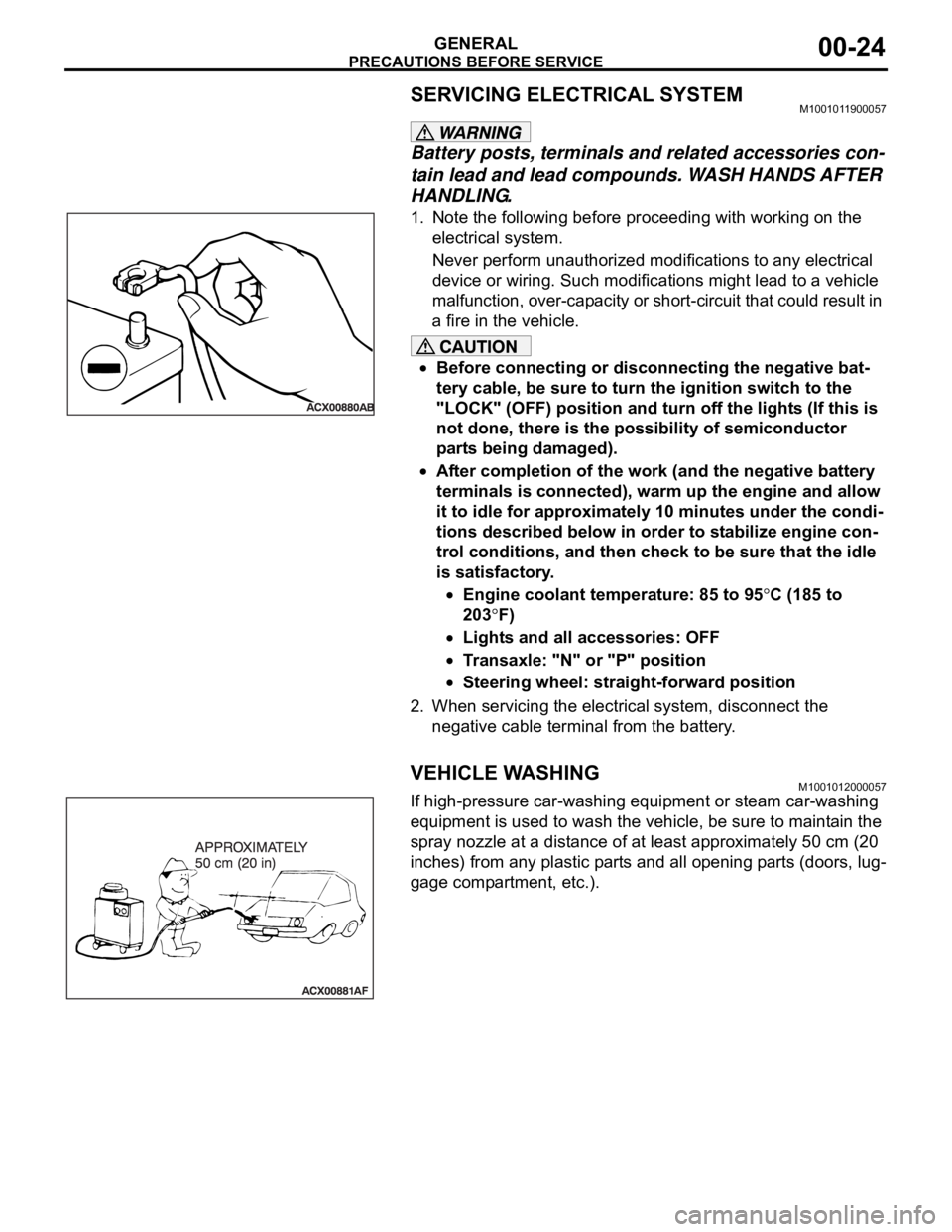
VEHICLE WASHINGM1001012000057
If high-pressure car-washing equipment or steam car-washing
equipment is used to wash the vehicle, be sure to maintain the
spray nozzle at a distance of at least approximately 50 cm (20
inches) from any plastic parts and all opening parts (doors, lug-
gage compartment, etc.).
Page 1252 of 1500
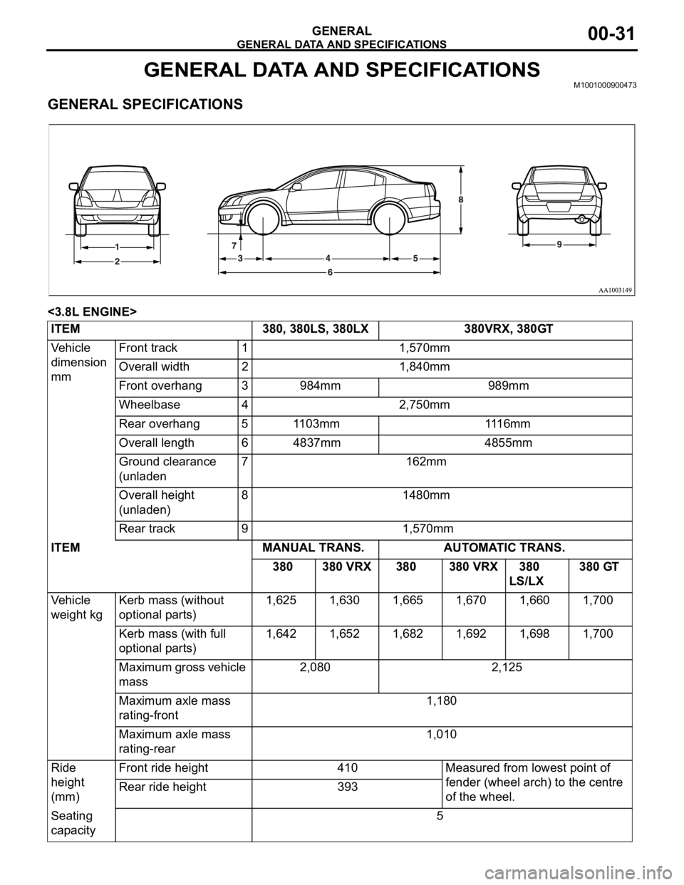
GENERAL DATA AND SPECIFICATIONS
GENERAL00-31
GENERAL DATA AND SPECIFICATIONSM1001000900473.
GENERAL SPECIFICATIONS
<3.8L ENGINE>
ITEM 380, 380LS, 380LX 380VRX, 380GT
Vehicle
dimension
mmFront track 1 1,570mm
Overall width 2 1,840mm
Front overhang 3 984mm 989mm
Wheelbase 4 2,750mm
Rear overhang 5 1103mm 1116mm
Overall length 6 4837mm 4855mm
Ground clearance
(unladen7 162mm
Overall height
(unladen)8 1480mm
Rear track 9 1,570mm
ITEM MANUAL TRANS. AUTOMATIC TRANS.
380 380 VRX 380 380 VRX 380
LS/LX 380 GT
Vehicle
weight kgKerb mass (without
optional parts) 1,625 1,630 1,665 1,670 1,660 1,700
Kerb mass (with full
optional parts) 1,642 1,652 1,682 1,692 1,698 1,700
Maximum gross vehicle
mass 2,080 2,125
Maximum axle mass
rating-front 1,180
Maximum axle mass
rating-rear 1,010
Ride
height
(mm)Front ride height 410 Measured from lowest point of
fender (wheel arch) to the centre
of the wheel. Rear ride height 393
Seating
capacity 5
Page 1253 of 1500

TIGHTENING TORQUE
GENERAL00-32
TIGHTENING TORQUEM1001001100555
Each torque value in the table is a standard value for
tightening under the following conditions.
1. Bolts, nuts and washers are all made of steel and
plated with zinc.
2. The threads and bearing surface of bolts and
nuts are all in dry condition.
The values in the table are not applicable:1. If toothed washers are inserted.
2. If plastic parts are fastened.
3. If bolts are tightened to plastic or die-cast
inserted nuts.
4. If self-tapping screws or self-locking nuts are
used.
STANDARD BOLT AND NUT TIGHTENING TORQUE Engine Model No. 6G75
Total displacement 3,828cc
Automatic
TransaxleModel No. F5A5A-4-C2Z
Type 5-speed automatic
Manual
Trans.Model No. F 5M51
Type 5-speed manual
Fuel
systemFuel supply system Electronic controlled multipoint fuel injection (MPI) ITEM 380, 380LS, 380LX 380VRX, 380GT
THREAD SIZE STANDARD TIGHTENING TORQUE
NOMINAL BOLT
DIAMETER (mm)PITCH
(mm)HEAD MARK "4" HEAD MARK "7" HEAD MARK "8"
M5 0.8 2.5
0.5 Nm (23 4
in-lb)5.0 1.0 Nm (44 9
in-lb)6.0 1.0 Nm (53 9
in-lb)
M6 1.0 5.0
1.0 Nm (44 9
in-lb)8.5 1.5 Nm (76 13
in-lb)10 2 Nm (89 17
in-lb)
M8 1.25 11
2 Nm (98 17
in-lb)20 4 Nm (15 3 ft-lb) 24 4 Nm (18 3 ft-lb)
M10 1.25 23
4 Nm (17 3 ft-lb) 42 8 Nm (31 6 ft-lb) 53 7 Nm (39 5 ft-lb)
M12 1.25 42
8 Nm (31 6 ft-lb) 80 10 Nm (59 7
ft-lb)93 12 Nm (68 9
ft-lb)
M14 1.5 70
10 Nm (52 7
ft-lb)130 20 Nm (96 15
ft-lb)150 20 Nm ( 111 14
ft-lb)
M16 1.5 105
15 Nm (78 11
ft-lb)195 25 Nm (144 18
ft-lb)230 30 Nm (170 22
ft-lb)
M18 1.5 150
20 Nm ( 111 14
ft-lb)290 40 Nm (214 29
ft-lb)335 45 Nm (247 33
ft-lb)
Page 1255 of 1500
LUBRICATION AND MAINTENANCE
GENERAL00-34
LUBRICATION AND MAINTENANCEM1001001200336
Maintenance and lubrication service recommenda-
tions have been compiled to provide maximum pro-
tection for the vehicle owner's investment against all
reasonable types of driving conditions. Since these
conditions vary with the individual vehicle owner's
driving habits, the area in which the vehicle is oper-
ated and the type of driving to which the vehicle is
subjected, it is necessary to prescribe lubrication and
maintenance service on a time frequency as well as
mileage interval basis.
Oils, lubricants and greases are classified and
graded according to standards recommended by the
Society of Automotive Engineers (SAE) and the Aus-
tralian Petroleum Institute (API).
MAINTENANCE SCHEDULES
For Information on service maintenance refer to the
"Service handbook".
ENGINE OIL
Tests have shown that laboratory animals
develop skin cancer after prolonged contact with
used engine oil. Accordingly, the potential exists
for humans to develop a number of skin disor-
ders, including cancer, from such exposure to
used engine oil. Therefore, when changing
engine oil, be careful not to touch it as much as
possible. Protective clothing and gloves, that
cannot be penetrated by oil, should be worn. The
skin should be thoroughly washed with soap and
water, or use waterless hand cleaner, to remove
any used engine oil. Do not use petrol, thinners,
or solvents.Either of the following engine oils should be used:
1. Engine oil conforming to the ACEA classification:
"For service A1, A2 or A3.
2. Engine oil conforming to the API classification:
"For service SG" or higher.
FUEL USAGE STATEMENT
Using leaded petrol in this car will damage the
catalytic converters and heated oxygen sensors,
and affect the warranty coverage validity.
This vehicle must use unleaded petrol only.
This vehicle has a fuel filler tube which is especially
designed to accept only the smaller-diameter
unleaded petrol dispensing nozzle.
The 3.8L model is designed to operate on unleaded
petrol having an octane rating (DIN 51607) of 90
RON or higher.
.
PETROL CONTAINING ALCOHOL
Some petrol sold at service stations contain alcohol
although they may not be so identified.
Using fuels containing alcohol is not recommended
unless the nature of the blend can be determined as
being satisfactory, as follows.
Gasohol: A mixture of 10% ethanol and 90%
unleaded gasoline may be used in your vehicle. If
driveability problems are experienced as a result of
using gasohol, it is recommended that the vehicle be
operated on petrol.
Methanol: Do not use petrol containing methanol
(wood alcohol). Using this type of alcohol can result
in vehicle performance deterioration and damage
critical parts in the fuel system components. Fuel
system damage and performance problems resulting
from the use of petrol containing methanol may not
be covered by the new vehicle warranty.
MATERIALS ADDED TO FUEL
Indiscriminate use of fuel system cleaning agents
should be avoided. Many materials intended for gum
and varnish removal may contain highly active sol-
vents or similar ingredients that can be harmful to
gasket and diaphragm materials used in fuel system
component parts.
Page 1256 of 1500

RECOMMENDED LUBRICANTS AND LUBRICANT CAPACITIES TABLE
GENERAL00-35
RECOMMENDED LUBRICANTS AND LUBRICANT
CAPACITIES TABLE
M1001001300504
RECOMMENDED LUBRICANTS
LUBRICANT CAPACITY TABLE
<3.8L ENGINE>LUBRICANT SPECIFICATION
Engine oil Engine oils conforming to ACEA A1, A2 or A3 and
AP1 SG or higher
AutomaticTransmission fluid Genuine Mitsubishi Motors ATF-SP III
Manual Transmission fluid Genuine Mitsubishi Motors MTF
Power steering fluid ATF DEXRON III or DEXRON II
Brakes fluid Conforming to DOT 3 or DOT 4
Engine coolant Genuine Mitsubishi Motors coolant
Refrigerant (air conditioning) HFC-134a
DESCRIPTION SPECIFICATION
Engine oil (Litres) Oil pan (excluding oil filter) 4.0
Oil filter 0.3
Engine coolant (Litres) 8.7
Automatic Transmission fluid (Litres) 8.4
Manual Transmission fluid (Litres) 2.8
Power steering fluid (Litres) 1.2
Fuel tank (Litres) 67.0
Washer fluid (Litres) 5.0
Refrigerant (air conditioning) (grams) 435g - 475g