Ignition circuit MITSUBISHI 380 2005 Manual Online
[x] Cancel search | Manufacturer: MITSUBISHI, Model Year: 2005, Model line: 380, Model: MITSUBISHI 380 2005Pages: 1500, PDF Size: 47.87 MB
Page 590 of 1500

CENTRALISED JUNCTION
CIRCUIT DIAGRAMS90-13
19 Front-ECU (Field
effect transistor for
headlamp: Low)Fuse 10 Red Headlamp (LH) and headlamp (Low:
LH)
20 Front-ECU (Taillamp
relay)7.5 Brown A/C-ECU, A/T selector lever position
illumination lamp, combination meter,
fog lamp switch, headlamp (RH),
glove box lamp, hazard warning lamp
switch, multi-center display unit,
radio, CD player, rear combination
lamp (RH), rheostat and TCL switch
21 7.5 Brown Headlamp (LH), license plate lamp
and rear combination lamp (LH)
22 Battery/Alternator
(Fusible link No.27)15 Blue A/C-ECU, column switch,
combination meter, ETACS-ECU,
front-ECU, key reminder switch, multi-
center display unit, radio, CD player,
and vanity mirror lamp
23 Ignition switch (ACC) 10 Red A/C-ECU, accessory socket relay,
ETACS-ECU, multi-center display
unit, radio, CD player.
24 Battery/Alternator
(Fusible link No.27)15 Blue Fuel pump module
25 Ignition switch (ACC) 30 Green Front-ECU and windshield wiper
motor
26 Battery/Alternator
(Fusible link No.27)Fusible
link20 Light blue Anti-lock braking system(solenoid
valve)
27
Alternator120
Battery, front-ECU, fusible link Nos.1,
2, 3, 4, 5 and 26 and fuse Nos.6, 7, 8,
9, 10, 11, 13, 14, 15, 22 and 24 (in
relay box) NO. POWER SUPPLY
CIRCUITNAME RATED
CAPACITY (A)HOUSING
COLOURLOAD CIRCUIT
Page 592 of 1500

CENTRALISED JUNCTION
CIRCUIT DIAGRAMS90-15
NO. POWER SUPPLY
CIRCUITNAME RATED
CAPACITY (A)HOUSING
COLOURLOAD CIRCUIT
1 Fusible link No.1 Fuse 30 Green Rear window demister
2 30 Green Blower motor and resistor
3
4
5 15 Blue Accessory socket
6 15 Blue Data link connector and ETACS-ECU
7 Ignition switch (ACC) 15 Blue ETACS-ECU
8
9 Ignition switch (IG2) 7.5 Brown Sunroof assembly
10 Ignition switch (ACC) 7.5 Brown Remote controlled mirror
11
12
13 Ignition switch (IG1) 7.5 Brown Fuel pump relay and Engine ECU
14 Ignition switch (ACC) 20 Yellow Windscreen wiper
15 Fusible link No.1
(Fuse No.5 in junction
block)7.5 Brown Remote controlled mirror
16 Ignition switch (IG2) 7.5 Brown A/C compressor clutch relay,
A/C-ECU, blower relay, condenser
fan motor, fan control relay,
front-ECU, outside/inside air selection
damper control motor and rear
window defogger relay
17 Ignition switch (IG1)
18 7.5 Brown A/T control relay, input shaft speed
sensor, output shaft speed sensor,
Engine ECU, rear combination lamp
and SRS-ECU
19 7.5 Brown ABS-ECU, ABS/TCL-ECU, column
switch, combination meter,
ETACS-ECU, multi-center display unit
and SRS-ECU
20 10 Red Ignition coil
21
22
23 Fusible link No.5 20 Yellow Sunroof assembly
24
Page 599 of 1500
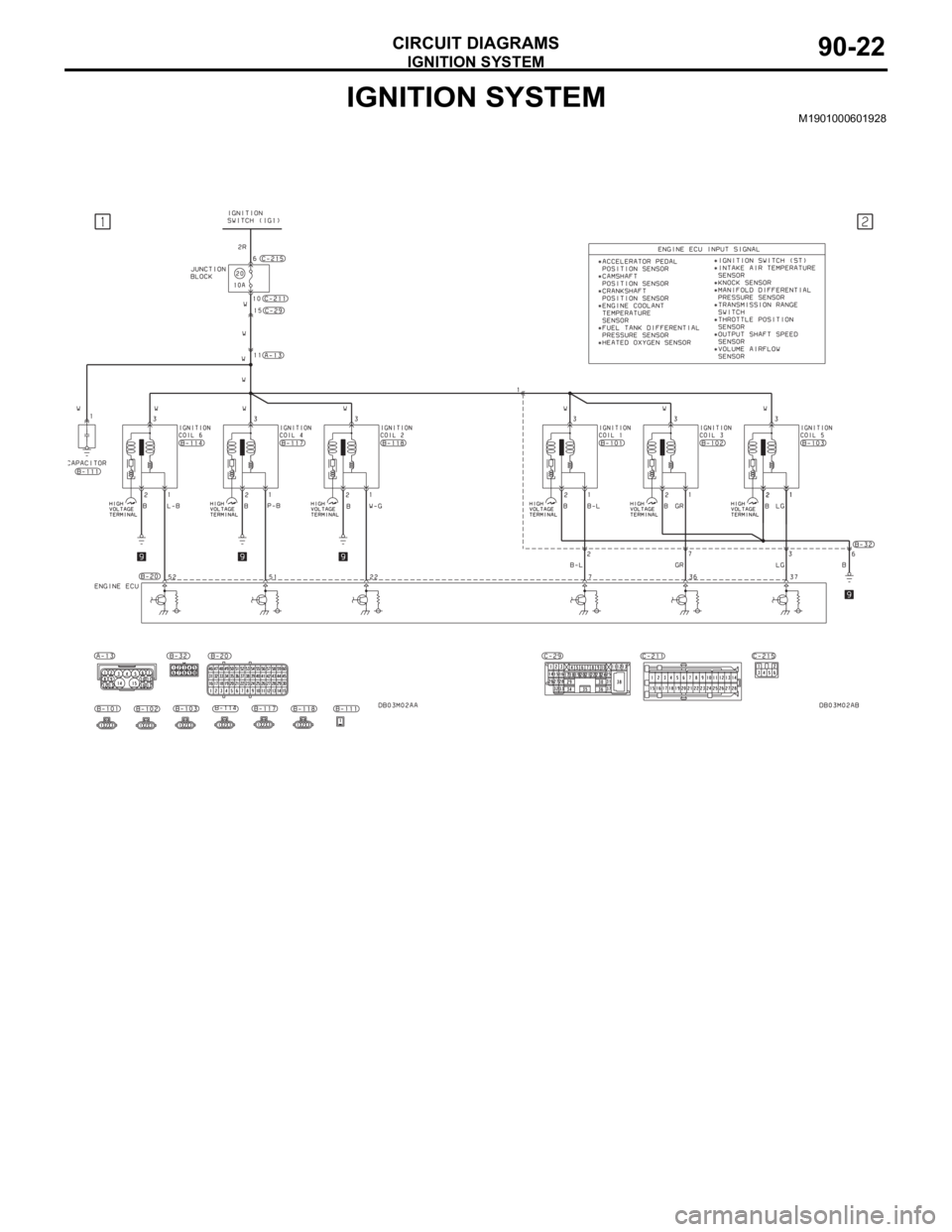
IGNITION SYSTEM
CIRCUIT DIAGRAMS90-22
IGNITION SYSTEMM1901000601928
Page 621 of 1500

FRONT DOME LAMP, REAR DOME LAMP, TRUNK LAMP AND IGNITION KEY HOLE ILLUMINATION LAMP
CIRCUIT DIAGRAMS90-44
FRONT DOME LAMP, REAR DOME LAMP, TRUNK LAMP
AND IGNITION KEY HOLE ILLUMINATION LAMP
M1901002100313
Page 622 of 1500
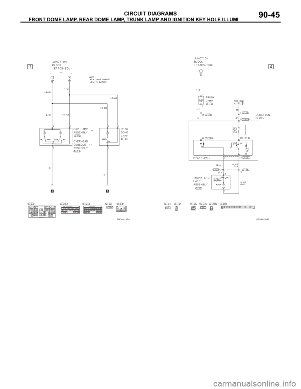
FRONT DOME LAMP, REAR DOME LAMP, TRUNK LAMP AND IGNITION KEY HOLE ILLUMINATION LAMP
CIRCUIT DIAGRAMS90-45
Page 623 of 1500
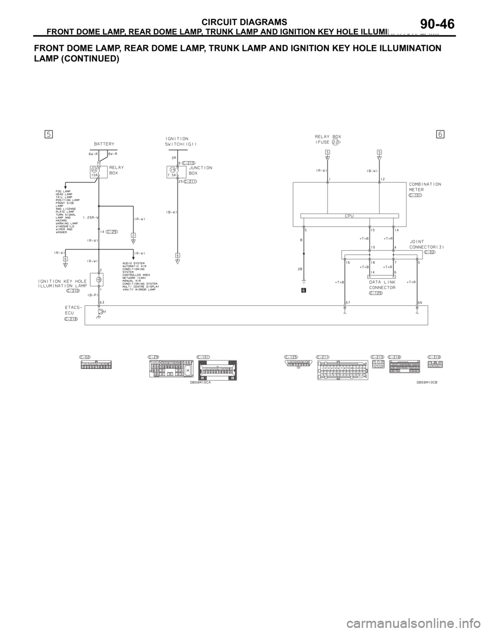
FRONT DOME LAMP, REAR DOME LAMP, TRUNK LAMP AND IGNITION KEY HOLE ILLUMINATION LAMP
CIRCUIT DIAGRAMS90-46
FRONT DOME LAMP, REAR DOME LAMP, TRUNK LAMP AND IGNITION KEY HOLE ILLUMINATION
LAMP (CONTINUED)
Page 624 of 1500
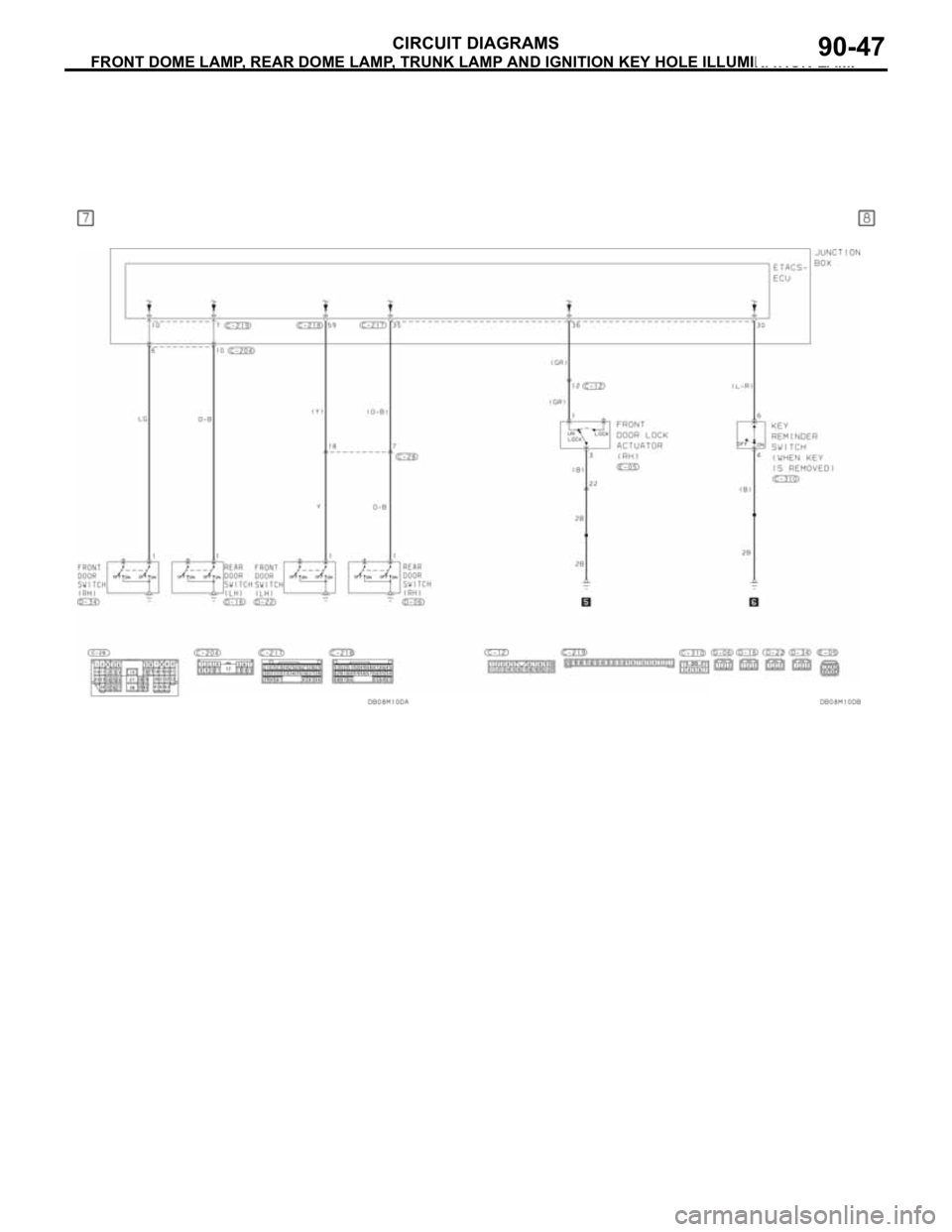
FRONT DOME LAMP, REAR DOME LAMP, TRUNK LAMP AND IGNITION KEY HOLE ILLUMINATION LAMP
CIRCUIT DIAGRAMS90-47
Page 689 of 1500
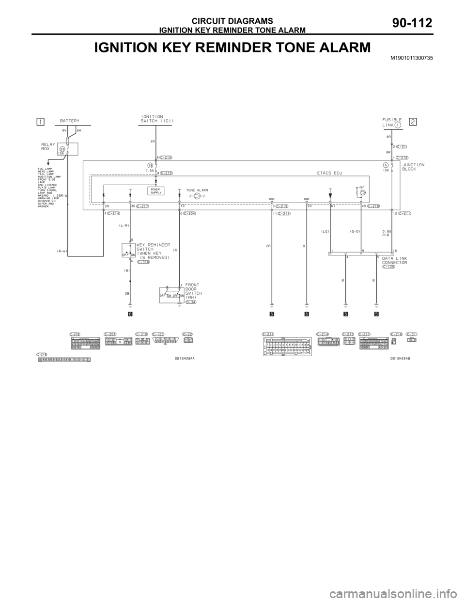
IGNITION KEY REMINDER TONE ALARM
CIRCUIT DIAGRAMS90-112
IGNITION KEY REMINDER TONE ALARMM1901011300735
Page 705 of 1500

GENERAL DESCRIPTION
HEATER, AIR CONDITIONING AND VENTILATION55-4
OPERATION
.
CONDENSER FAN AND RADIATOR FAN
CONTROL
The ECU judges the required revolution speed of
radiator fan motor and condenser fan motor using
the input signals transmitted from A/C switch, output
shaft speed sensor and engine coolant temperature
sensor. The ECU activates the fan control relays to
drive the radiator fan motor and condenser fan
motor.
.
COMPRESSOR CONTROL
When operating the air conditioning switch
The air thermo sensor, which senses the temper-
ature of the air flowing out of the evaporator,
deactivates the compressor at 3
C (37.4F) or
below.
The dual pressure switch turns OFF when the
refrigerant pressure becomes excessively high or
low, thus protecting the compressor circuit (See
Table below).
When the air thermo sensor is activated, and the
ignition switch, blower switch, and air condition-
ing switch are ON, the A/C compressor clutch
relay is energized.
When operating the mode selection dial
The air conditioning will work when the mode
selection dial is set to the "Defroster" or
"Defroster/foot" position, or the temperature con-
trol dial is set to the "MAX A/C" position. In other
dial positions, when the air conditioning switch is
turned on, the air conditioning will work.
A/C Compressor Clutch Relay ON Conditions
Ignition switch (IG2) ONNOTE: A/C compressor clutch relay is
de-energized when any one switch, sensor
or control unit shown on the left turns off.
NOTE: The components marked by
*
communicate with the ECU. If the air thermo
sensor detects a temperature of 3
C
(37.4
F), the A/C-ECU will turn off the A/C
compressor clutch relay. Blower switch ON
Air conditioning switch, mode selection dial
defroster, defroster/foot position or temperature
control MAX A/CON
Air thermo sensor*
Pressure detected
by A/C pressure
sensor2940 kPa or less (If the
refrigerant pressure exceeds
2940 kPa, A/C compressor
clutch relay is not ON
condition until the refrigerant
pressure has been measured
up to 2350 kPa or less.)ON
190 kPa or more (If the
refrigerant pressure falls short
of 190 kPa, A/C compressor
clutch relay is not ON
condition until the refrigerant
pressure has been measured
up to 220 kPa or more.)
A/C compressor clutch relay driving transistor (within
ecu)ON
Page 710 of 1500
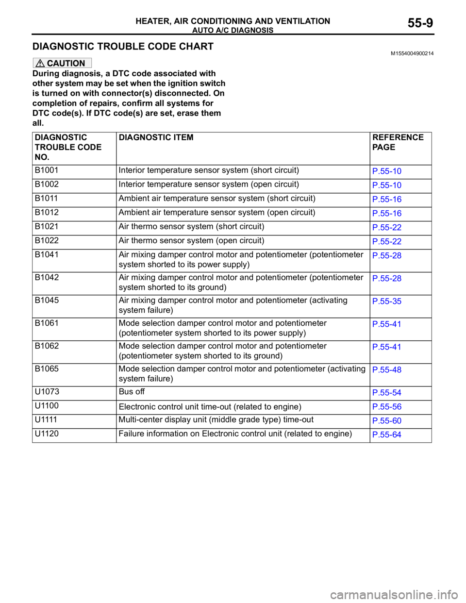
AUTO A/C DIAGNOSIS
HEATER, AIR CONDITIONING AND VENTILATION55-9
DIAGNOSTIC TROUBLE CODE CHART M1554004900214
During diagnosis, a DTC code associated with
other system may be set when the ignition switch
is turned on with connector(s) disconnected. On
completion of repairs, confirm all systems for
DTC code(s). If DTC code(s) are set, erase them
all.
DIAGNOSTIC
TROUBLE CODE
NO.DIAGNOSTIC ITEM REFERENCE
PA G E
B1001 Interior temperature sensor system (short circuit)
P.55-10
B1002 Interior temperature sensor system (open circuit)
P.55-10
B1011 Ambient air temperature sensor system (short circuit)
P.55-16
B1012 Ambient air temperature sensor system (open circuit)
P.55-16
B1021 Air thermo sensor system (short circuit)
P.55-22
B1022 Air thermo sensor system (open circuit)
P.55-22
B1041 Air mixing damper control motor and potentiometer (potentiometer
system shorted to its power supply)P.55-28
B1042 Air mixing damper control motor and potentiometer (potentiometer
system shorted to its ground)P.55-28
B1045 Air mixing damper control motor and potentiometer (activating
system failure)P.55-35
B1061 Mode selection damper control motor and potentiometer
(potentiometer system shorted to its power supply)P.55-41
B1062 Mode selection damper control motor and potentiometer
(potentiometer system shorted to its ground)P.55-41
B1065 Mode selection damper control motor and potentiometer (activating
system failure)P.55-48
U1073 Bus off
P.55-54
U1100
Electronic control unit time-out (related to engine)P.55-56
U 1111 M u l t i - c e n t e r d i s p l a y u n i t ( m i d d l e g r a d e t y p e ) t i m e - o u t
P.55-60
U1120 Failure information on Electronic control unit (related to engine)
P.55-64