Ignition circuit MITSUBISHI 380 2005 Manual PDF
[x] Cancel search | Manufacturer: MITSUBISHI, Model Year: 2005, Model line: 380, Model: MITSUBISHI 380 2005Pages: 1500, PDF Size: 47.87 MB
Page 441 of 1500
INPUT SIGNAL PROCEDURES
SIMPLIFIED WIRING SYSTEM (SWS)54B-441
STEP 1. Check the input signal (by using the pulse check
mode of the monitor).
Check the input signals from the all door switches.
To prevent damage to diagnostic tool MB991958, always
turn the ignition switch to the "LOCK" (OFF) position
before connecting or disconnecting diagnostic tool
MB991958.
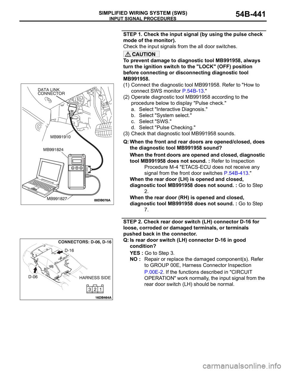
(1) Connect the diagnostic tool MB991958. Refer to "How to
connect SWS monitor P.54B-13."
(2) Operate diagnostic tool MB991958 according to the
procedure below to display "Pulse check."
a. Select "Interactive Diagnosis."
b. Select "System select."
c. Select "SWS."
d. Select "Pulse Checking."
(3) Check that diagnostic tool MB991958 sounds.
Q: When the front and rear doors are opened/closed, does
the diagnostic tool MB991958 sound?
When the front doors are opened and closed, diagnostic
tool MB991958 does not sound. : Refer to Inspection
Procedure M-4 "ETACS-ECU does not receive any
signal from the front door switches P.54B-413."
When the rear door (LH) is opened and closed,
diagnostic tool MB991958 does not sound. : Go to Step
2.
When the rear door (RH) is opened and closed,
diagnostic tool MB991958 does not sound. : Go to Step
7.
STEP 2. Check rear door switch (LH) connector D-16 for
loose, corroded or damaged terminals, or terminals
pushed back in the connector.
Q: Is rear door switch (LH) connector D-16 in good
condition?
YES : Go to Step 3.
NO : Repair or replace the damaged component(s). Refer
to GROUP 00E, Harness Connector Inspection
P.00E-2. If the functions described in "CIRCUIT
OPERATION" work normally, the input signal from the
rear door switch (LH) should be normal.
Page 452 of 1500
INPUT SIGNAL PROCEDURES
SIMPLIFIED WIRING SYSTEM (SWS)54B-452
DIAGNOSIS
Required Special Tools:
MB991223: Harness Set
MB991958: Diagnostic Tool (MUT-III Sub Assembly)
MB991824: Vehicle Communication Interface (V.C.I.)
MB991827: MUT-III USB Cable
MB991910: MUT-III Main Harness A
STEP 1. Check the input signal (by using the pulse check
mode of the monitor).
Check the input signals from the front door lock actuators.
To prevent damage to diagnostic tool MB991958, always
turn the ignition switch to the "LOCK" (OFF) position
before connecting or disconnecting diagnostic tool
MB991958.
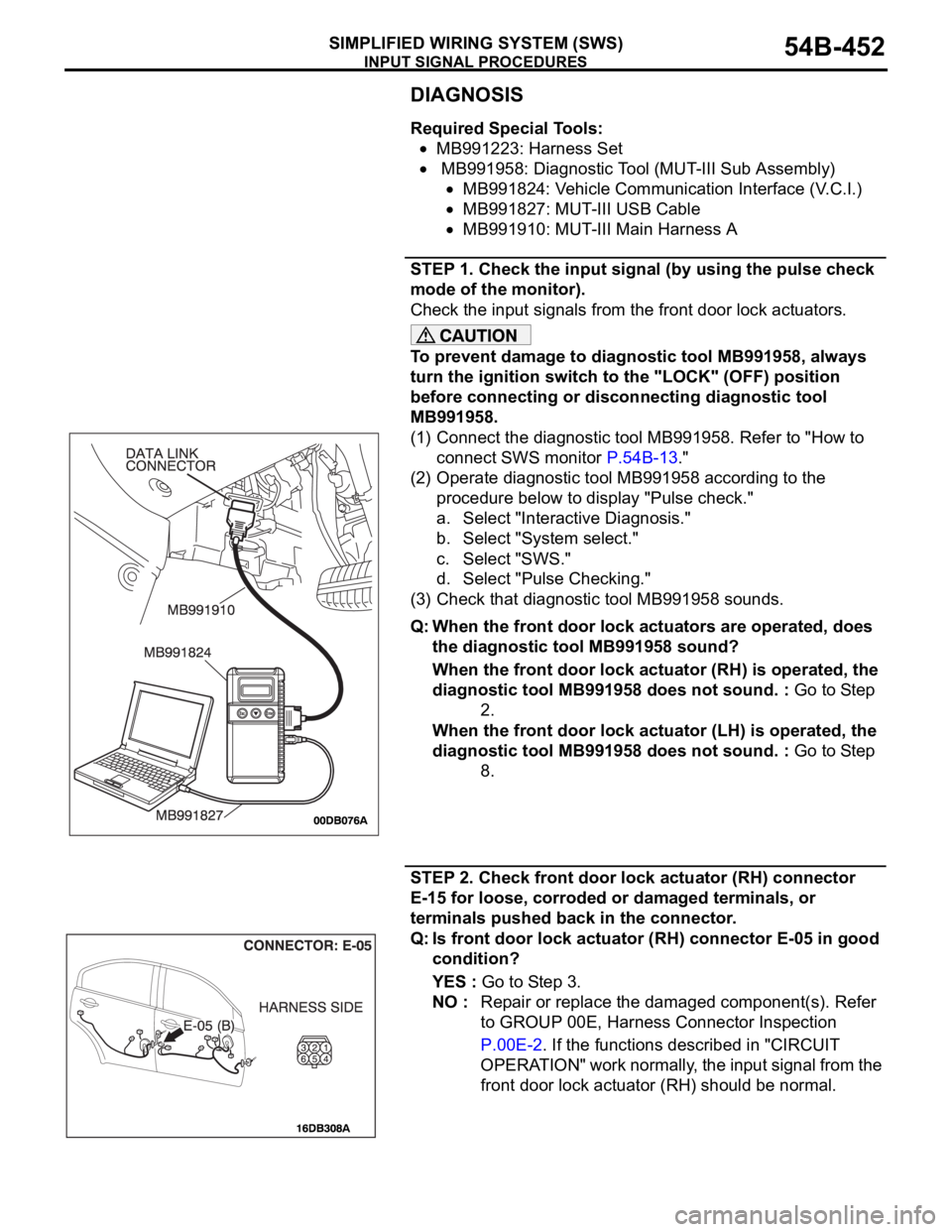
(1) Connect the diagnostic tool MB991958. Refer to "How to
connect SWS monitor P.54B-13."
(2) Operate diagnostic tool MB991958 according to the
procedure below to display "Pulse check."
a. Select "Interactive Diagnosis."
b. Select "System select."
c. Select "SWS."
d. Select "Pulse Checking."
(3) Check that diagnostic tool MB991958 sounds.
Q: When the front door lock actuators are operated, does
the diagnostic tool MB991958 sound?
When the front door lock actuator (RH) is operated, the
diagnostic tool MB991958 does not sound. : Go to Step
2.
When the front door lock actuator (LH) is operated, the
diagnostic tool MB991958 does not sound. : Go to Step
8.
STEP 2. Check front door lock actuator (RH) connector
E-15 for loose, corroded or damaged terminals, or
terminals pushed back in the connector.
Q: Is front door lock actuator (RH) connector E-05 in good
condition?
YES : Go to Step 3.
NO : Repair or replace the damaged component(s). Refer
to GROUP 00E, Harness Connector Inspection
P.00E-2. If the functions described in "CIRCUIT
OPERATION" work normally, the input signal from the
front door lock actuator (RH) should be normal.
Page 474 of 1500
INPUT SIGNAL PROCEDURES
SIMPLIFIED WIRING SYSTEM (SWS)54B-474
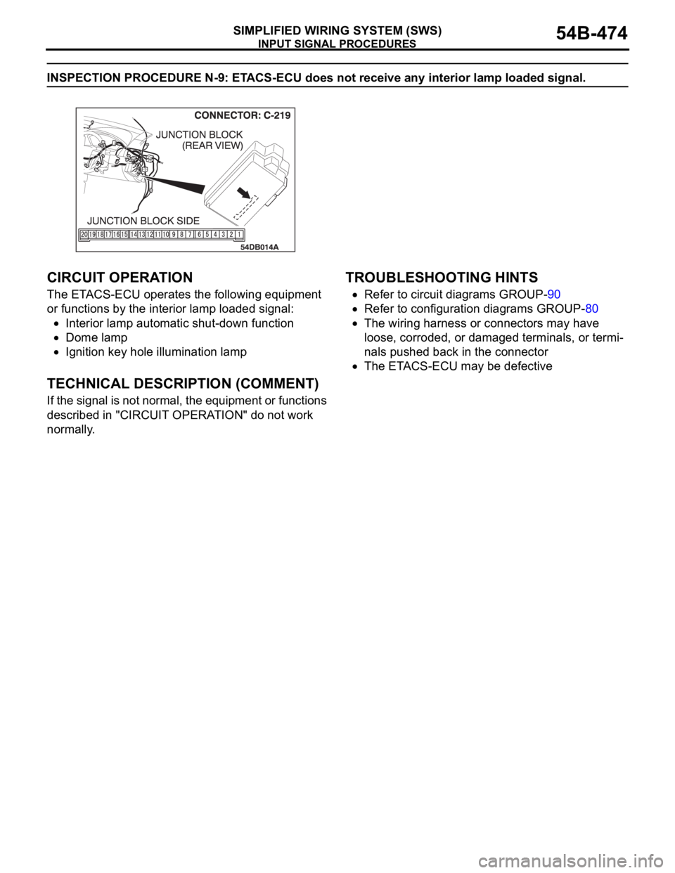
INSPECTION PROCEDURE N-9: ETACS-ECU does not receive any interior lamp loaded signal.
.
CIRCUIT OPERATION
The ETACS-ECU operates the following equipment
or functions by the interior lamp loaded signal:
Interior lamp automatic shut-down function
Dome lamp
Ignition key hole illumination lamp
.
TECHNICAL DESCRIPTION (COMMENT)
If the signal is not normal, the equipment or functions
described in "CIRCUIT OPERATION" do not work
normally.
.
TROUBLESHOOTING HINTS
Refer to circuit diagrams GROUP-90
Refer to configuration diagrams GROUP-80
The wiring harness or connectors may have
loose, corroded, or damaged terminals, or termi-
nals pushed back in the connector
The ETACS-ECU may be defective
Page 477 of 1500
INPUT SIGNAL PROCEDURES
SIMPLIFIED WIRING SYSTEM (SWS)54B-477
STEP 4. Check the ignition switch (IG1) line of the power
supply circuit to the ETACS-ECU. Measure the voltage at
ETACS-ECU connector C-219.
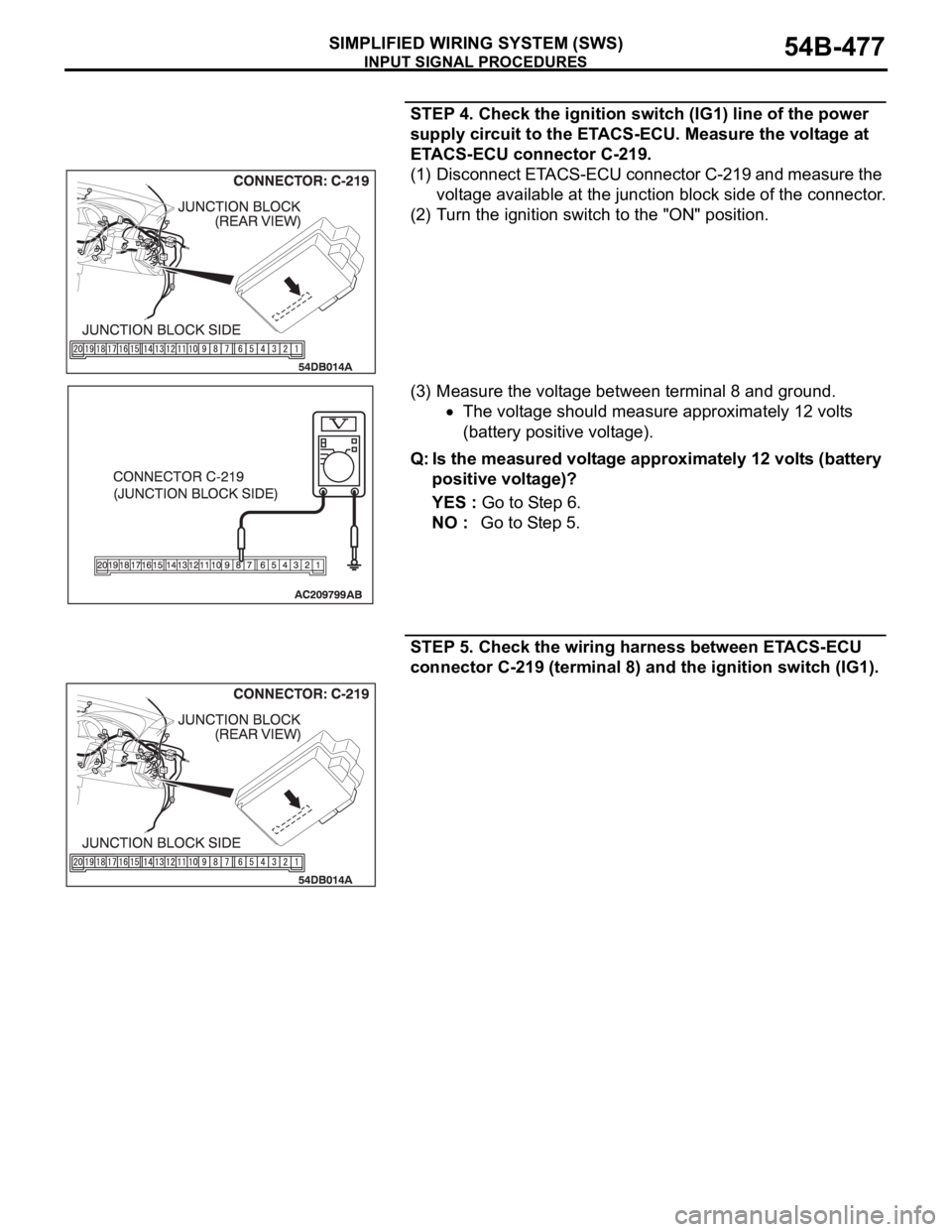
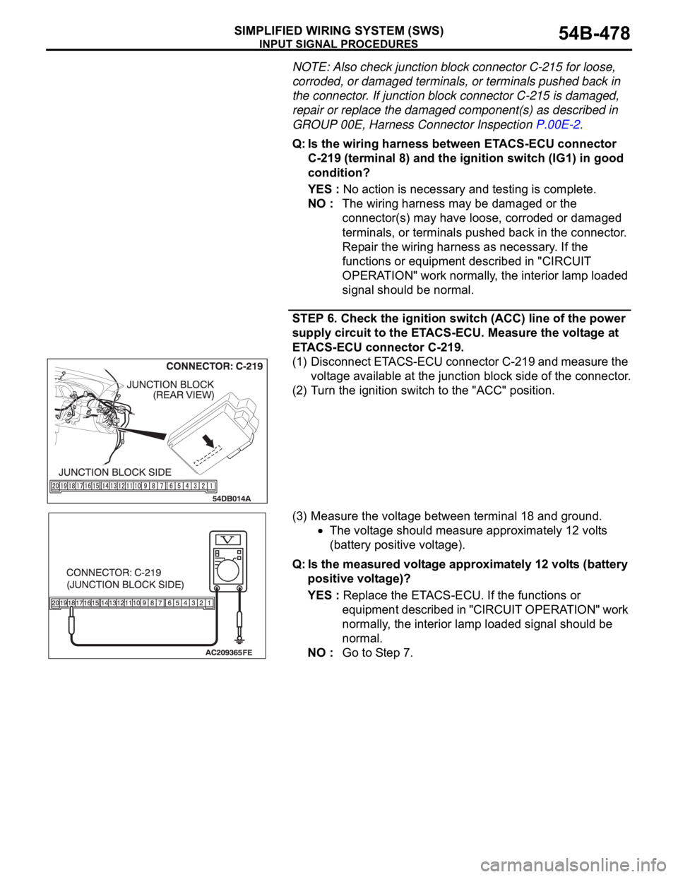
(1) Disconnect ETACS-ECU connector C-219 and measure the
voltage available at the junction block side of the connector.
(2) Turn the ignition switch to the "ON" position.
(3) Measure the voltage between terminal 8 and ground.
The voltage should measure approximately 12 volts
(battery positive voltage).
Q: Is the measured voltage approximately 12 volts (battery
positive voltage)?
YES : Go to Step 6.
NO : Go to Step 5.
STEP 5. Check the wiring harness between ETACS-ECU
connector C-219 (terminal 8) and the ignition switch (IG1).
Page 478 of 1500
INPUT SIGNAL PROCEDURES
SIMPLIFIED WIRING SYSTEM (SWS)54B-478
NOTE: Also check junction block connector C-215 for loose,
corroded, or damaged terminals, or terminals pushed back in
the connector. If junction block connector C-215 is damaged,
repair or replace the damaged component(s) as described in
GROUP 00E, Harness Connector Inspection P.00E-2.
Q: Is the wiring harness between ETACS-ECU connector
C-219 (terminal 8) and the ignition switch (IG1) in good
condition?
YES : No action is necessary and testing is complete.
NO : The wiring harness may be damaged or the
connector(s) may have loose, corroded or damaged
terminals, or terminals pushed back in the connector.
Repair the wiring harness as necessary. If the
functions or equipment described in "CIRCUIT
OPERATION" work normally, the interior lamp loaded
signal should be normal.
STEP 6. Check the ignition switch (ACC) line of the power
supply circuit to the ETACS-ECU. Measure the voltage at
ETACS-ECU connector C-219.
(1) Disconnect ETACS-ECU connector C-219 and measure the
voltage available at the junction block side of the connector.
(2) Turn the ignition switch to the "ACC" position.
(3) Measure the voltage between terminal 18 and ground.
The voltage should measure approximately 12 volts
(battery positive voltage).
Q: Is the measured voltage approximately 12 volts (battery
positive voltage)?
YES : Replace the ETACS-ECU. If the functions or
equipment described in "CIRCUIT OPERATION" work
normally, the interior lamp loaded signal should be
normal.
NO : Go to Step 7.
Page 479 of 1500
INPUT SIGNAL PROCEDURES
SIMPLIFIED WIRING SYSTEM (SWS)54B-479
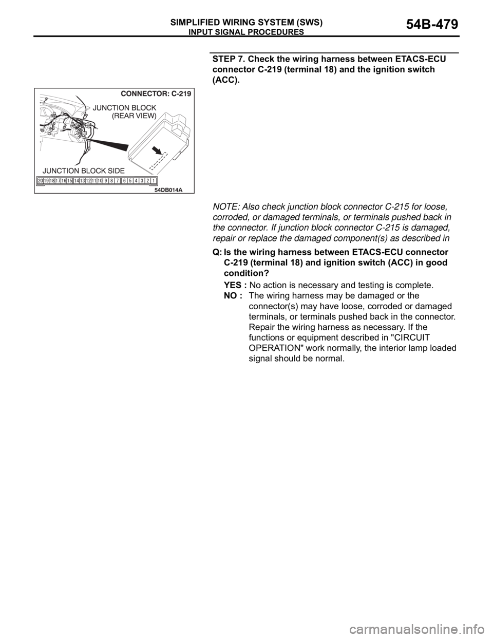
STEP 7. Check the wiring harness between ETACS-ECU
connector C-219 (terminal 18) and the ignition switch
(ACC).
NOTE: Also check junction block connector C-215 for loose,
corroded, or damaged terminals, or terminals pushed back in
the connector. If junction block connector C-215 is damaged,
repair or replace the damaged component(s) as described in
Q: Is the wiring harness between ETACS-ECU connector
C-219 (terminal 18) and ignition switch (ACC) in good
condition?
YES : No action is necessary and testing is complete.
NO : The wiring harness may be damaged or the
connector(s) may have loose, corroded or damaged
terminals, or terminals pushed back in the connector.
Repair the wiring harness as necessary. If the
functions or equipment described in "CIRCUIT
OPERATION" work normally, the interior lamp loaded
signal should be normal.
Page 514 of 1500

FRONT SEAT ASSEMBLY
INTERIOR52A-25
MEMORY SEAT DIAGNOSIS
POWER SEAT SUPPLY AND GROUND CONNECTOR (D-40)
SPECIAL TOOL:
MB991219: Inspection Test Harness
CIRCUIT DIAGRAMS:
Refer to circuit diagrams GROUP-90
Refer to configuration diagrams GROUP-80
NOTE: Check connectors and terminals for damage or
loose connections at the seat harness and all supply
circuits connections to seat. Repair or replace wiring
harness if damaged.
NOTE: The special tool (Inspection test harness) MB991219
for connector pin contact pressure should be used. The test
probe should never be forcibly inserted, as it may cause a
defective contact.
10-WAY TRACK (MEMORY)- SOURCE TO (MSC) POWER
CONNECTOR (D-38)
NOTE: The special tool (Inspection test harness) MB991219
for connector pin contact pressure should be used. The test
probe should never be forcibly inserted, as it may cause a
defective contact. SUPPLY TEST
CONNECTION
(D-40) SPECIFIED CONDITION
BATTERY
SUPPLY112V
GROUND 2 Less than 2 ohms or 0V
CIRCUIT
DESCRIPTION TEST CONNECTION
(MSC)
POWER
(D-38) SOURCE INTERMEDIATE
CONNECTOR
GROUND 1 GROUND 15 -
"NEUTRAL" 2 A/T-ECU (B-19) 31 (B-25) pin 9
Bus LT 3 - -
IGNITION- LED ON 4 (IGN 2) J/B fuse 9 (C-28) pin 35
DOOR SW.- LED ON 5 RH Door sw. (D-34) 2 -
VEHICLE SPEED 6 A/T-ECU (B-19) 24 (C-25) pin 8
"PARK" 7 A/T-ECU (B-19) 30 (C-25) pin 10
N.C - - -
Page 578 of 1500
90-1
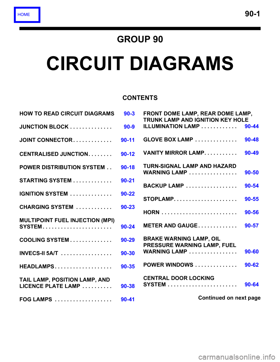
GROUP 90
CIRCUIT DIAGRAMS
CONTENTS
HOW TO READ CIRCUIT DIAGRAMS90-3
JUNCTION BLOCK . . . . . . . . . . . . . .90-9
JOINT CONNECTOR . . . . . . . . . . . . .90-11
CENTRALISED JUNCTION . . . . . . . .90-12
POWER DISTRIBUTION SYSTEM . .90-18
STARTING SYSTEM . . . . . . . . . . . . .90-21
IGNITION SYSTEM . . . . . . . . . . . . . .90-22
CHARGING SYSTEM . . . . . . . . . . . .90-23
MULTIPOINT FUEL INJECTION (MPI)
SYSTEM . . . . . . . . . . . . . . . . . . . . . . .90-24
COOLING SYSTEM . . . . . . . . . . . . . .90-29
INVECS-II 5A/T . . . . . . . . . . . . . . . . .90-30
HEADLAMPS . . . . . . . . . . . . . . . . . . .90-35
TAIL LAMP, POSITION LAMP, AND
LICENCE PLATE LAMP . . . . . . . . . .90-38
FOG LAMPS . . . . . . . . . . . . . . . . . . .90-41FRONT DOME LAMP, REAR DOME LAMP,
TRUNK LAMP AND IGNITION KEY HOLE
ILLUMINATION LAMP . . . . . . . . . . . .90-44
GLOVE BOX LAMP . . . . . . . . . . . . . .90-48
VANITY MIRROR LAMP. . . . . . . . . . .90-49
TURN-SIGNAL LAMP AND HAZARD
WARNING LAMP . . . . . . . . . . . . . . . .90-50
BACKUP LAMP . . . . . . . . . . . . . . . . .90-54
STOPLAMP. . . . . . . . . . . . . . . . . . . . .90-55
HORN . . . . . . . . . . . . . . . . . . . . . . . . .90-56
METER AND GAUGE . . . . . . . . . . . . .90-57
BRAKE WARNING LAMP, OIL
PRESSURE WARNING LAMP, FUEL
WARNING LAMP . . . . . . . . . . . . . . . .90-60
POWER WINDOWS . . . . . . . . . . . . . .90-62
CENTRAL DOOR LOCKING
SYSTEM . . . . . . . . . . . . . . . . . . . . . . .90-64
Continued on next page
Page 579 of 1500
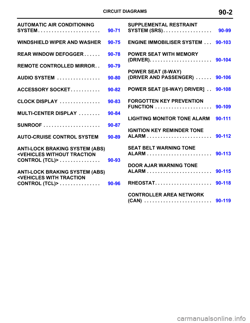
CIRCUIT DIAGRAMS90-2
AUTOMATIC AIR CONDITIONING
SYSTEM . . . . . . . . . . . . . . . . . . . . . . .90-71
WINDSHIELD WIPER AND WASHER90-75
REAR WINDOW DEFOGGER . . . . . .90-78
REMOTE CONTROLLED MIRROR . .90-79
AUDIO SYSTEM . . . . . . . . . . . . . . . .90-80
ACCESSORY SOCKET . . . . . . . . . . .90-82
CLOCK DISPLAY . . . . . . . . . . . . . . .90-83
MULTI-CENTER DISPLAY . . . . . . . .90-84
SUNROOF . . . . . . . . . . . . . . . . . . . . .90-87
AUTO-CRUISE CONTROL SYSTEM90-89
ANTI-LOCK BRAKING SYSTEM (ABS)
ANTI-LOCK BRAKING SYSTEM (ABS)
SYSTEM (SRS) . . . . . . . . . . . . . . . . . .90-99
ENGINE IMMOBILISER SYSTEM . . .90-103
POWER SEAT WITH MEMORY
(DRIVER). . . . . . . . . . . . . . . . . . . . . . .90-104
POWER SEAT (8-WAY)
(DRIVER AND PASSENGER) . . . . . .90-106
POWER SEAT [(6-WAY) DRIVER] . .90-108
FORGOTTEN KEY PREVENTION
FUNCTION . . . . . . . . . . . . . . . . . . . . .90-109
LIGHTING MONITOR TONE ALARM90-111
IGNITION KEY REMINDER TONE
ALARM . . . . . . . . . . . . . . . . . . . . . . . .90-112
SEAT BELT WARNING TONE
ALARM . . . . . . . . . . . . . . . . . . . . . . . .90-113
DOOR AJAR WARNING TONE
ALARM . . . . . . . . . . . . . . . . . . . . . . . .90-115
RHEOSTAT . . . . . . . . . . . . . . . . . . . . .90-118
CONTROLLER AREA NETWORK
(CAN) . . . . . . . . . . . . . . . . . . . . . . . . .90-119
Page 589 of 1500

CENTRALISED JUNCTION
CIRCUIT DIAGRAMS90-12
CENTRALISED JUNCTIONM1901000301013
FUSIBLE LINK AND FUSE
ENGINE COMPARTMENT
NO. POWER SUPPLY
CIRCUITNAME RATED
CAPACITY (A)HOUSING
COLOURLOAD CIRCUIT
1 Battery/Alternator
(Fusible link No.27)Fusible
link80 Black Fuse Nos.5, 6, 9 and 10 (in junction
block) circuit
2 50 Blue Radiator fan motor
3 30 Pink ABS-ECU and ABS/TCL-ECU (motor
power supply)
4 40 Green Ignition switch circuit
5 40 Green Fuse Nos.3 and 4 (in junction block
circuit), front power window regulator
motor, power seat assembly, power
window main switch and rear power
window regulator motor
6 Fuse 15 Blue Fog lamp and fog lamp relay
720Yellow
8 15 Red Horn (High), horn (Low) and horn
relay
9 20 Yellow Camshaft position sensor, crankshaft
position sensor, engine oil control
valve, evaporative emission purge
solenoid, evaporative emission
ventilation solenoid, heated oxygen
sensor,ETACS-ECU, injector, mass
airflow sensor, MPI relay, Engine
ECU, A/T ECU, throttle actuator
control motor relay and fan control
relay
10 10 Red A/C compressor assembly and
A/C-ECU
11 15 Blue ABS-ECU, ABS/TCL-ECU,
high-mounted stoplamp, Engine ECU
and rear combination lamp
12
13 7.5 Brown
Alternator
14 10 Red ETACS-ECU, Hazard lamps
15 20 Yellow A/T control solenoid valve and Engine
ECU
16 Front-ECU
(Headlamp relay:
High)15 Blue Headlamp (RH) and headlamp (High:
RH)
17 15 Blue Headlamp (LH) and headlamp (High:
LH)
18 Front-ECU (Field
effect transistor for
headlamp: Low)10 Red Headlamp (RH) and headlamp (Low:
RH)