Cruis control MITSUBISHI 380 2005 Workshop Manual
[x] Cancel search | Manufacturer: MITSUBISHI, Model Year: 2005, Model line: 380, Model: MITSUBISHI 380 2005Pages: 1500, PDF Size: 47.87 MB
Page 565 of 1500
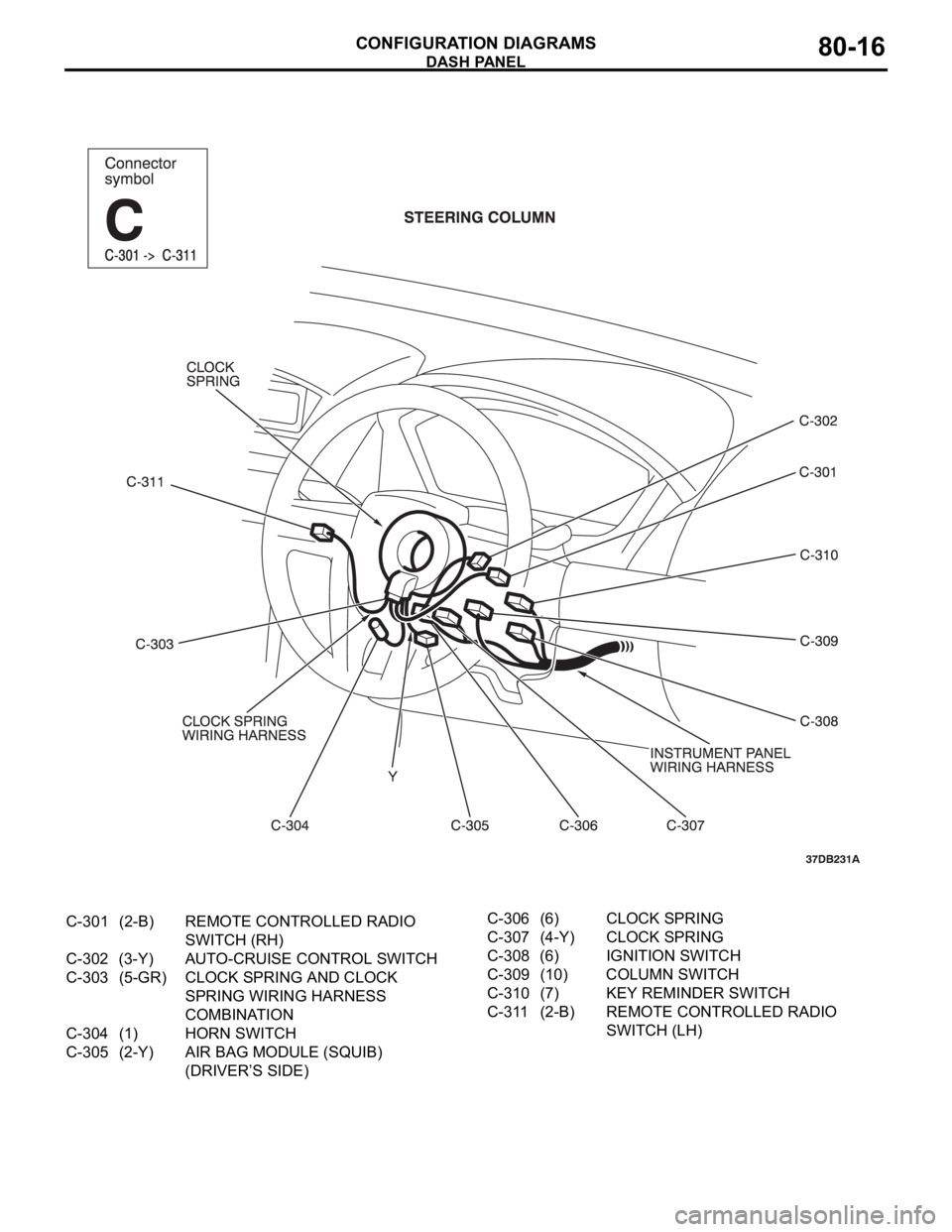
DASH PANEL
CONFIGURATION DIAGRAMS80-16
C-301 (2-B) REMOTE CONTROLLED RADIO
SWITCH (RH)
C-302 (3-Y) AUTO-CRUISE CONTROL SWITCH
C-303 (5-GR) CLOCK SPRING AND CLOCK
SPRING WIRING HARNESS
COMBINATION
C-304 (1) HORN SWITCH
C-305 (2-Y) AIR BAG MODULE (SQUIB)
(DRIVER’S SIDE)C-306 (6) CLOCK SPRING
C-307 (4-Y) CLOCK SPRING
C-308 (6) IGNITION SWITCH
C-309 (10) COLUMN SWITCH
C-310 (7) KEY REMINDER SWITCH
C-311 (2-B) REMOTE CONTROLLED RADIO
SWITCH (LH)
Page 579 of 1500
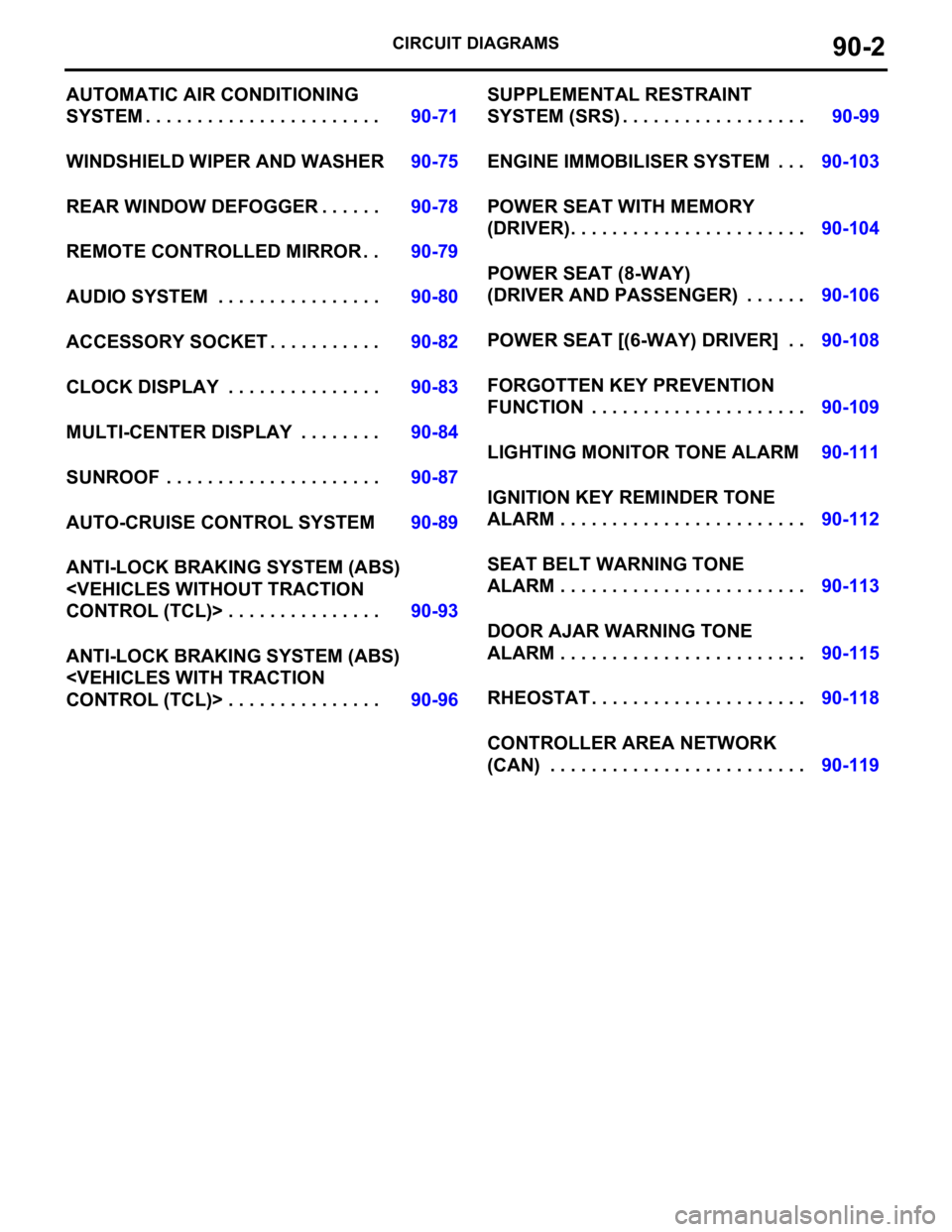
CIRCUIT DIAGRAMS90-2
AUTOMATIC AIR CONDITIONING
SYSTEM . . . . . . . . . . . . . . . . . . . . . . .90-71
WINDSHIELD WIPER AND WASHER90-75
REAR WINDOW DEFOGGER . . . . . .90-78
REMOTE CONTROLLED MIRROR . .90-79
AUDIO SYSTEM . . . . . . . . . . . . . . . .90-80
ACCESSORY SOCKET . . . . . . . . . . .90-82
CLOCK DISPLAY . . . . . . . . . . . . . . .90-83
MULTI-CENTER DISPLAY . . . . . . . .90-84
SUNROOF . . . . . . . . . . . . . . . . . . . . .90-87
AUTO-CRUISE CONTROL SYSTEM90-89
ANTI-LOCK BRAKING SYSTEM (ABS)
ANTI-LOCK BRAKING SYSTEM (ABS)
SYSTEM (SRS) . . . . . . . . . . . . . . . . . .90-99
ENGINE IMMOBILISER SYSTEM . . .90-103
POWER SEAT WITH MEMORY
(DRIVER). . . . . . . . . . . . . . . . . . . . . . .90-104
POWER SEAT (8-WAY)
(DRIVER AND PASSENGER) . . . . . .90-106
POWER SEAT [(6-WAY) DRIVER] . .90-108
FORGOTTEN KEY PREVENTION
FUNCTION . . . . . . . . . . . . . . . . . . . . .90-109
LIGHTING MONITOR TONE ALARM90-111
IGNITION KEY REMINDER TONE
ALARM . . . . . . . . . . . . . . . . . . . . . . . .90-112
SEAT BELT WARNING TONE
ALARM . . . . . . . . . . . . . . . . . . . . . . . .90-113
DOOR AJAR WARNING TONE
ALARM . . . . . . . . . . . . . . . . . . . . . . . .90-115
RHEOSTAT . . . . . . . . . . . . . . . . . . . . .90-118
CONTROLLER AREA NETWORK
(CAN) . . . . . . . . . . . . . . . . . . . . . . . . .90-119
Page 666 of 1500
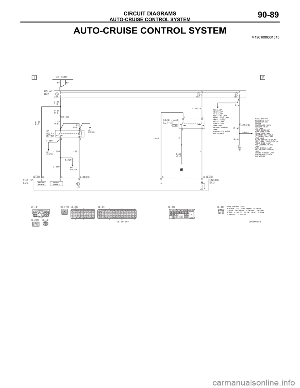
AUTO-CRUISE CONTROL SYSTEM
CIRCUIT DIAGRAMS90-89
AUTO-CRUISE CONTROL SYSTEMM1901009301515
Page 667 of 1500
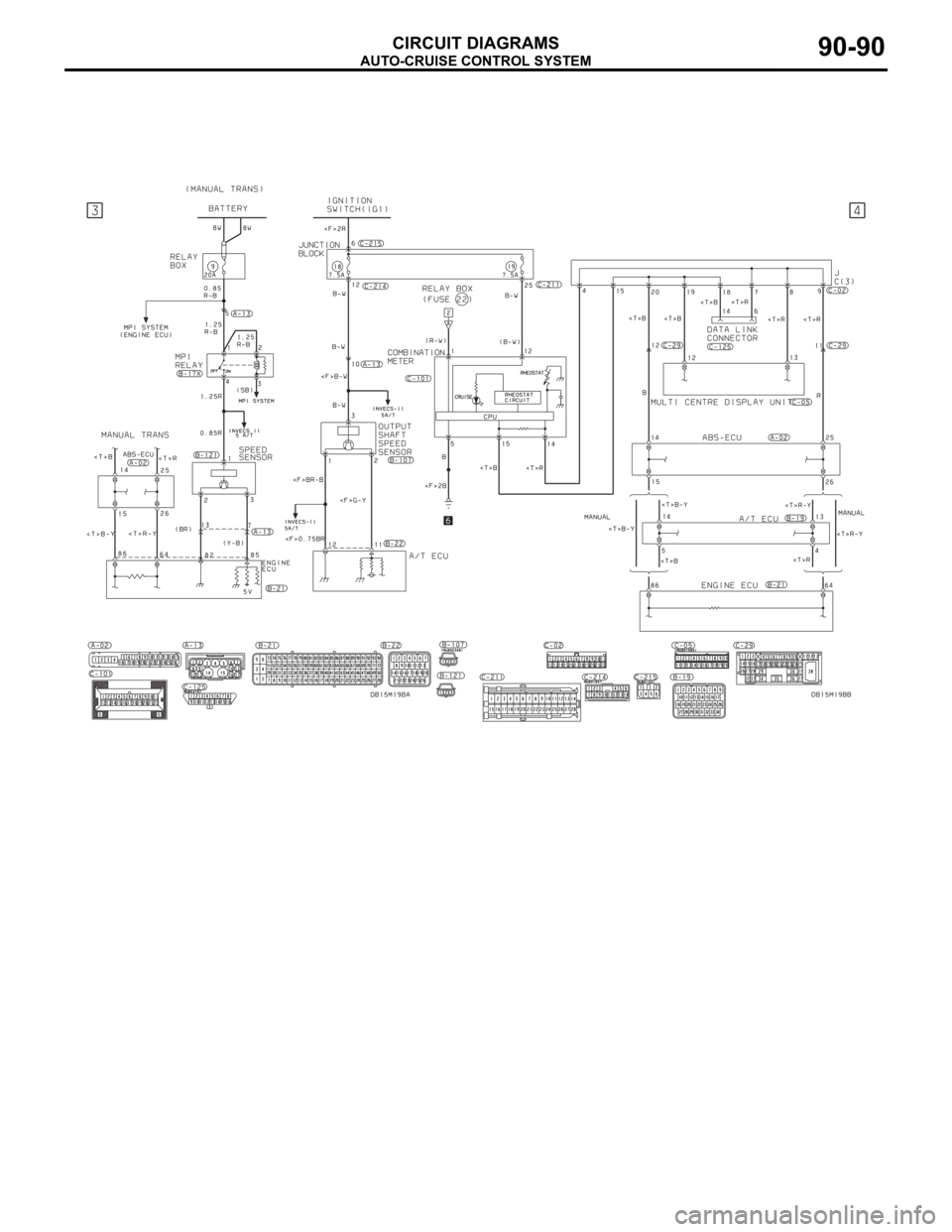
AUTO-CRUISE CONTROL SYSTEM
CIRCUIT DIAGRAMS90-90
Page 668 of 1500
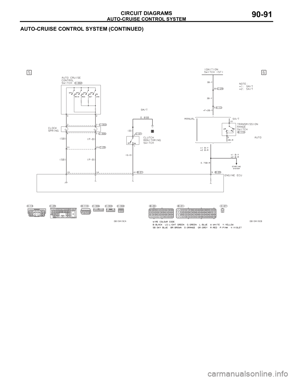
AUTO-CRUISE CONTROL SYSTEM
CIRCUIT DIAGRAMS90-91
AUTO-CRUISE CONTROL SYSTEM (CONTINUED)
Page 669 of 1500
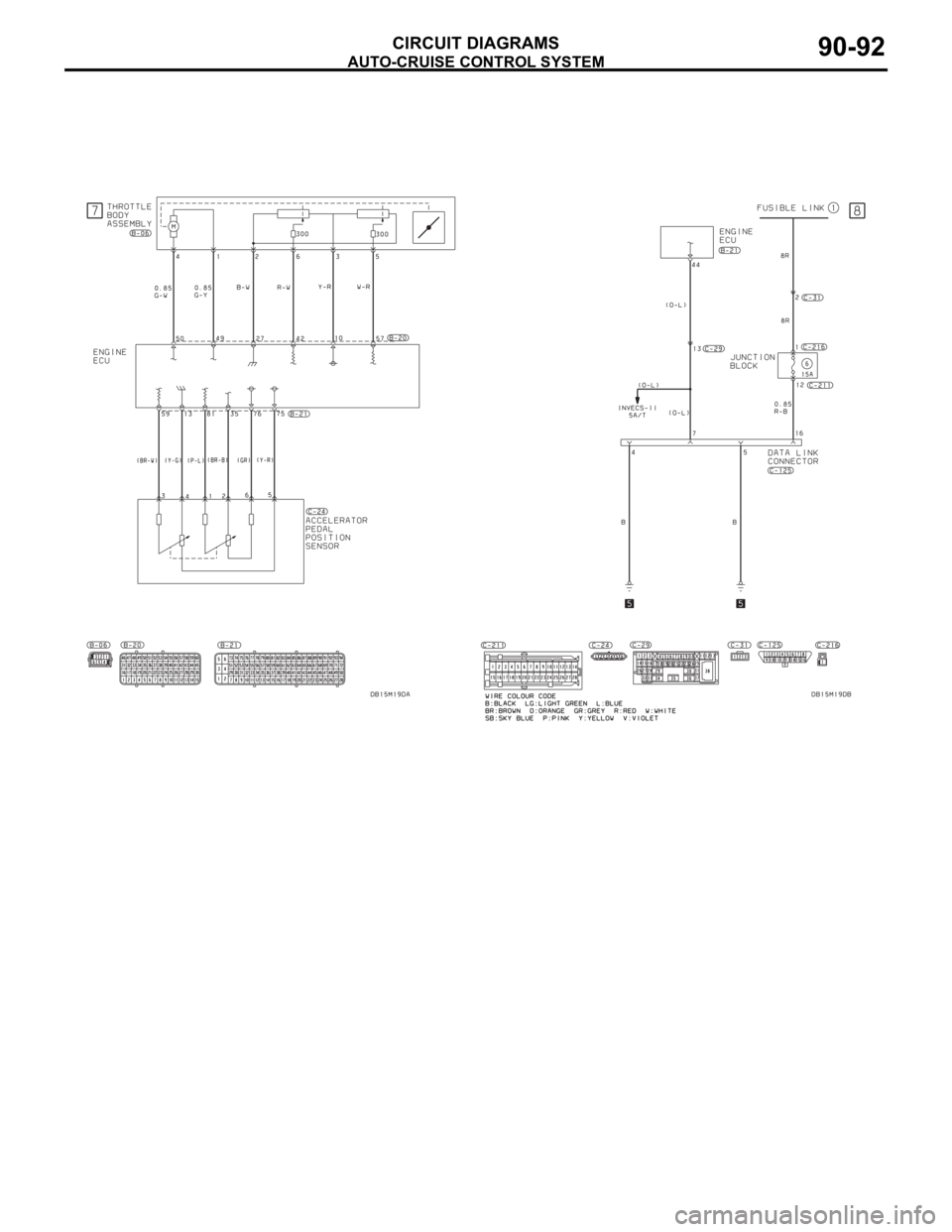
AUTO-CRUISE CONTROL SYSTEM
CIRCUIT DIAGRAMS90-92
Page 1332 of 1500
17-1
GROUP 17
ENGINE AND
EMISSION
CONTROL
CONTENTS
ENGINE CONTROL. . . . . . . . . .
17-3
GENERAL DESCRIPTION . . . . . .
17-3
ENGINE CONTROL SYSTEM
DIAGNOSIS . . . . . . . . . . . . . . . . . .
17-3
INTRODUCTION . . . . . . . . . . . . . . . . . . 17-3
TROUBLESHOOTING STRATEGY . . . 17-3
SYMPTOM CHART . . . . . . . . . . . . . . . . 17-4
SYMPTOM PROCEDURES . . . . . . . . . 17-4
SPECIAL TOOL . . . . . . . . . . . . . . .17-8
ACCELERATOR PEDAL . . . . . . . .17-9
REMOVAL AND INSTALLATION . . . . . 17-9
AUTO-CRUISE CONTROL . . . .17-10
GENERAL DESCRIPTION . . . . . .
17-10
AUTO-CRUISE CONTROL SYSTEM
DIAGNOSIS . . . . . . . . . . . . . . . . . .
17-10
INTRODUCTION TO AUTO-CRUISE
CONTROL SYSTEM DIAGNOSIS . . . . . 17-10
DIAGNOSTIC TROUBLESHOOTING
STRATEGY . . . . . . . . . . . . . . . . . . . . . . 17-11
DIAGNOSTIC FUNCTION . . . . . . . . . . . 17-11
DIAGNOSTIC TROUBLE CODE CHART17-14
DIAGNOSTIC TROUBLE CODE
PROCEDURES . . . . . . . . . . . . . . . . . . . 17-15
SYMPTOM CHART . . . . . . . . . . . . . . . . 17-53
SYMPTOM PROCEDURES . . . . . . . . . . 17-54
DATA LIST REFERENCE TABLE . . . . . 17-65
ENGINE ECU TERMINAL VOLTAGE
REFERENCE CHART FOR AUTO-CRUISE
CONTROL SYSTEM OPERATION . . . . 17-67
SPECIAL TOOLS . . . . . . . . . . . . . .17-69
ON-VEHICLE SERVICE . . . . . . . . .17-71
AUTO-CRUISE CONTROL SWITCH
CHECK . . . . . . . . . . . . . . . . . . . . . . . . . . 17-71
AUTO-CRUISE CONTROL SYSTEM
COMPONENT CHECK. . . . . . . . . . . . . . 17-73
AUTO-CRUISE CONTROL. . . . . . .17-75
REMOVAL AND INSTALLATION . . . . . . 17-75
Continued on next page
Page 1341 of 1500
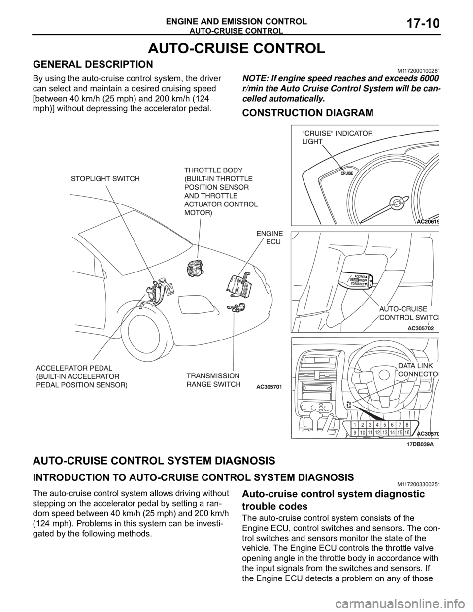
AUTO-CRUISE CONTROL
ENGINE AND EMISSION CONTROL17-10
AUTO-CRUISE CONTROL
GENERAL DESCRIPTIONM1172000100281
By using the auto-cruise control system, the driver
can select and maintain a desired cruising speed
[between 40 km/h (25 mph) and 200 km/h (124
mph)] without depressing the accelerator pedal.NOTE: If engine speed reaches and exceeds 6000
r/min the Auto Cruise Control System will be can-
celled automatically.
CONSTRUCTION DIAGRAM
AUTO-CRUISE CONTROL SYSTEM DIAGNOSIS
INTRODUCTION TO AUTO-CRUISE CONTROL SYSTEM DIAGNOSISM1172003300251
The auto-cruise control system allows driving without
stepping on the accelerator pedal by setting a ran-
dom speed between 40 km/h (25 mph) and 200 km/h
(124 mph). Problems in this system can be investi-
gated by the following methods.Auto-cruise control system diagnostic
trouble codes
The auto-cruise control system consists of the
Engine ECU, control switches and sensors. The con-
trol switches and sensors monitor the state of the
vehicle. The Engine ECU controls the throttle valve
opening angle in the throttle body in accordance with
the input signals from the switches and sensors. If
the Engine ECU detects a problem on any of those
91
01
1
12
1
31
41
5
16 123
456
78
Page 1342 of 1500
AUTO-CRUISE CONTROL
ENGINE AND EMISSION CONTROL17-11
components, the Engine ECU estimates where the
problem may be occurring, and will set a diagnostic
trouble code. Diagnostic trouble codes cover the
auto-cruise control switch, stoplamp switch and
Engine ECU.
DIAGNOSTIC TROUBLESHOOTING STRATEGYM1172002000484
Use these steps to plan your diagnostic strategy. If
you follow them carefully, you will check most of the
possible causes of an auto-cruise control system
problem.
1. Gather information from the customer.
2. Verify that the condition described by the
customer exists.
3. Check the vehicle for any auto-cruise control
system DTC. (Refer to P.17-11, Diagnostic
Function
How to Read and Erase Diagnostic
Trouble Codes).
4. If you can verify the condition but no auto-cruise
control system DTCs are set, the malfunction may
be intermittent. (Refer to GROUP 00, How to Use
Troubleshooting/Inspection Service Points
How
to Cope with Intermittent Malfunctions P.00-14).5. If you can verify the condition but there are no
auto-cruise control system DTCs, or the system
cannot communicate with Diagnostic Tool
MB991958 (MUT-III sub assembly), and find the
fault. (Refer to P.17-53, Symptom Chart).
6. If there is an auto-cruise control system DTC,
record the number of the code, then erase the
code from Engine ECU memory using the
Diagnostic Tool MB991958 (MUT-III sub
assembly). (Refer to P.17-11, Diagnostic Function
How to Read and Erase Diagnostic Trouble
Codes).
7. Re-create the auto-cruise control system DTC set
conditions to see if the same Auto-cruise Control
System DTC will set again. (Refer to P.17-11,
Diagnostic Function
How to Read and Erase
Diagnostic Trouble Codes).
If the same Auto-cruise Control System DTC sets
again, perform the diagnostic procedures for the
set code. (Refer to P.17-14, Diagnostic Trouble
Code Chart).
DIAGNOSTIC FUNCTIONM1172004900171
HOW TO CONNECT THE DIAGNOSTIC TOOL.
Required Special Tools:
MB991958: Diagnostic Tool (MUT-III Sub Assembly)
MB991824: Vehicle Communication Interface (V.C.I.)
MB991827: MUT-III USB Cable
MB991910: MUT-III Main Harness A
Page 1343 of 1500
AUTO-CRUISE CONTROL
ENGINE AND EMISSION CONTROL17-12
To prevent damage to Diagnostic Tool MB991958, always
turn the ignition switch to the "LOCK" (OFF) position
before connecting or disconnecting Diagnostic Tool
MB991958.
1. Ensure that the ignition switch is at the "LOCK" (OFF)
position.
2. Start up the personal computer.
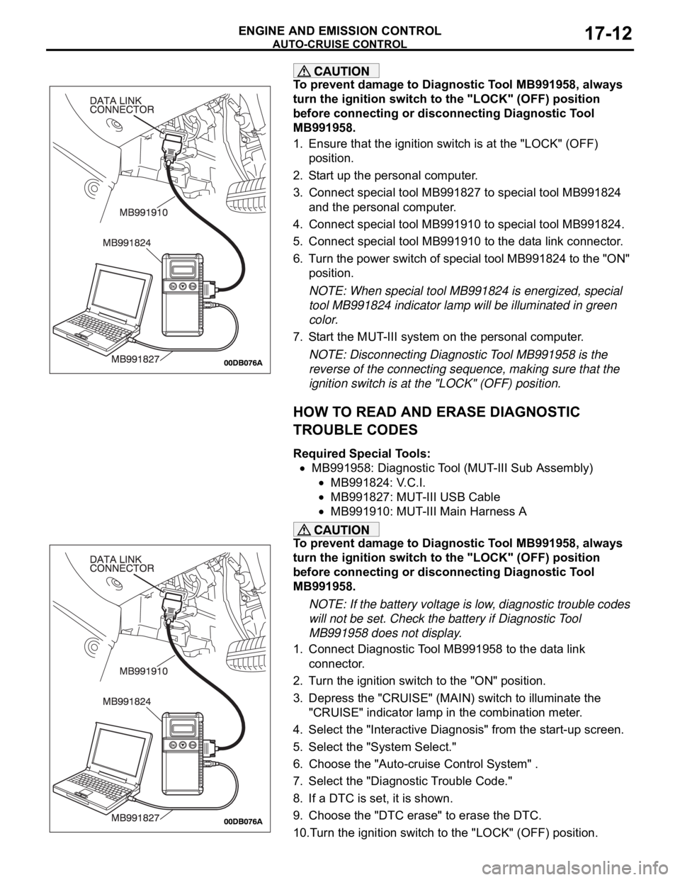
3. Connect special tool MB991827 to special tool MB991824
and the personal computer.
4. Connect special tool MB991910 to special tool MB991824.
5. Connect special tool MB991910 to the data link connector.
6. Turn the power switch of special tool MB991824 to the "ON"
position.
NOTE: When special tool MB991824 is energized, special
tool MB991824 indicator lamp will be illuminated in green
color.
7. Start the MUT-III system on the personal computer.
NOTE: Disconnecting Diagnostic Tool MB991958 is the
reverse of the connecting sequence, making sure that the
ignition switch is at the "LOCK" (OFF) position.
HOW TO READ AND ERASE DIAGNOSTIC
TROUBLE CODES
Required Special Tools:
MB991958: Diagnostic Tool (MUT-III Sub Assembly)
MB991824: V.C.I.
MB991827: MUT-III USB Cable
MB991910: MUT-III Main Harness A
To prevent damage to Diagnostic Tool MB991958, always
turn the ignition switch to the "LOCK" (OFF) position
before connecting or disconnecting Diagnostic Tool
MB991958.
NOTE: If the battery voltage is low, diagnostic trouble codes
will not be set. Check the battery if Diagnostic Tool
MB991958 does not display.
1. Connect Diagnostic Tool MB991958 to the data link
connector.
2. Turn the ignition switch to the "ON" position.
3. Depress the "CRUISE" (MAIN) switch to illuminate the
"CRUISE" indicator lamp in the combination meter.
4. Select the "Interactive Diagnosis" from the start-up screen.
5. Select the "System Select."
6. Choose the "Auto-cruise Control System" .
7. Select the "Diagnostic Trouble Code."
8. If a DTC is set, it is shown.
9. Choose the "DTC erase" to erase the DTC.
10.Turn the ignition switch to the "LOCK" (OFF) position.