MITSUBISHI COLT 2008 Owner's Manual (in English)
Manufacturer: MITSUBISHI, Model Year: 2008, Model line: COLT, Model: MITSUBISHI COLT 2008Pages: 450, PDF Size: 14.57 MB
Page 171 of 450
Starting and driving4-5
4
Running-in recommendations
E00600401170
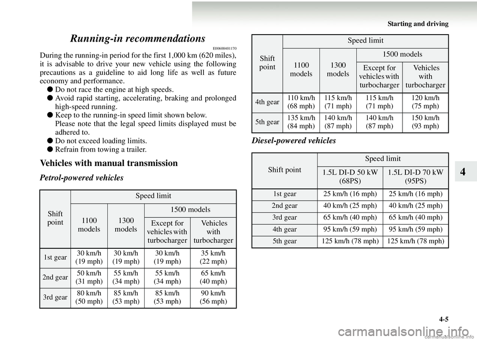
During the running-in period for the first 1,000 km (620 miles),
it is advisable to drive your new vehicle using the following
precautions as a guideline to aid
long life as well as future
economy and performance. ● Do not race the engine at high speeds.
● Avoid rapid starting, accelerating, braking and prolonged
high-speed running.
● Keep to the running-in speed limit shown below.
Please note that the legal speed limits displayed must be
adhered to.
● Do not exceed loading limits.
● Refrain from towing a trailer.
Vehicles with manual transmission
Petrol-powered vehicles Diesel-powered vehicles
Shift
point
Speed limit
1100
models1300
models
1500 models
Except for
vehicles with turbocharger Vehicles
with
turbocharger
1st gear 30 km/h
(19 mph) 30 km/h
(19 mph) 30 km/h
(19 mph) 35 km/h
(22 mph)
2nd gear 50 km/h
(31 mph) 55 km/h
(34 mph) 55 km/h
(34 mph) 65 km/h
(40 mph)
3rd gear 80 km/h
(50 mph) 85 km/h
(53 mph) 85 km/h
(53 mph) 90 km/h
(56 mph)
4th gear 110 km/h
(68 mph) 115 km/h
(71 mph) 115 km/h
(71 mph) 120 km/h
(75 mph)
5th gear 135 km/h
(84 mph) 140 km/h
(87 mph) 140 km/h
(87 mph) 150 km/h
(93 mph)
Shift point
Speed limit
1.5L DI-D 50 kW (68PS)1.5L DI-D 70 kW (95PS)
1st gear 25 km/h (16 mph) 25 km/h (16 mph)
2nd gear 40 km/h (25 mph) 40 km/h (25 mph)
3rd gear 65 km/h (40 mph) 65 km/h (40 mph)
4th gear 95 km/h (59 mph) 95 km/h (59 mph)
5th gear 125 km/h (78 mph) 125 km/h (78 mph)
Shift
point
Speed limit
1100
models1300
models
1500 models
Except for
vehicles with turbocharger Vehicles
with
turbocharger
Page 172 of 450
4-6 Starting and driving
4
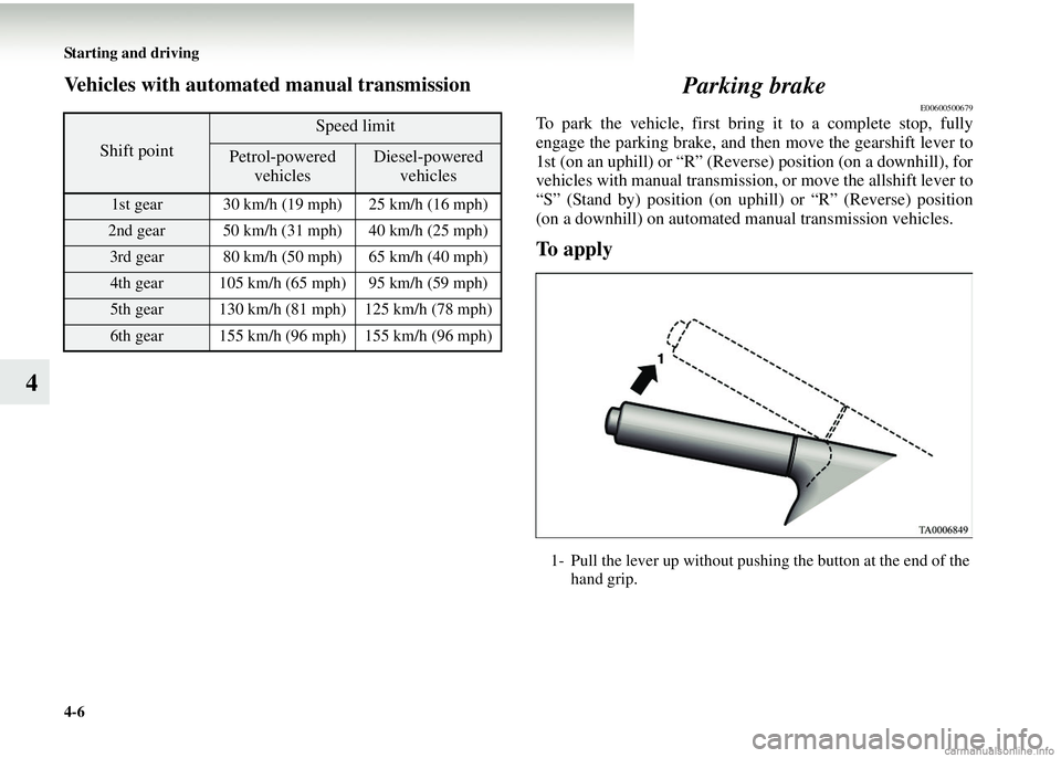
Vehicles with automated manual transmissionParking brake
E00600500679
To park the vehicle, first bring it to a complete stop, fully
engage the parking brake, and then move the gearshift lever to
1st (on an uphill) or “R” (Reverse) position (on a downhill), for
vehicles with manual transmission, or move the allshift lever to
“S” (Stand by) position (on uphill) or “R” (Reverse) position
(on a downhill) on automated manual transmission vehicles.
To apply
Shift point
Speed limit
Petrol-powered vehiclesDiesel-powered vehicles
1st gear 30 km/h (19 mph) 25 km/h (16 mph)
2nd gear 50 km/h (31 mph) 40 km/h (25 mph)
3rd gear 80 km/h (50 mph) 65 km/h (40 mph)
4th gear 105 km/h (65 mph) 95 km/h (59 mph)
5th gear 130 km/h (81 mph) 125 km/h (78 mph)
6th gear 155 km/h (96 mph) 155 km/h (96 mph)
1- Pull the lever up without pushing the button at the end of thehand grip.
Page 173 of 450
Starting and driving4-7
4
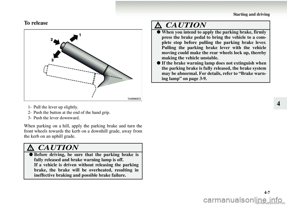
To r e l e a s e
When parking on a hill, apply the parking brake and turn the
front wheels towards the kerb on a downhill grade, away from
the kerb on an uphill grade.
1- Pull the lever up slightly.
2- Push the button at the end of the hand grip.
3- Push the lever downward.
CAUTION!
● Before driving, be sure that the parking brake is
fully released and brake warning lamp is off.
If a vehicle is driven wi thout releasing the parking
brake, the brake will be overheated, resulting in
ineffective brak ing and possible brake failure.
●When you intend to apply the parking brake, firmly
press the brake pedal to bring the vehicle to a com-
plete stop before pullin g the parking brake lever.
Pulling the parking brake lever with the vehicle
moving could make the rear wheels lock up, thereby
making the vehicle unstable.
● If the brake warning lamp does not extinguish when
the parking brake is fully released, the brake system
may be abnormal. For details, refer to “Brake warn-
ing lamp” on page 3-9.
CAUTION!
Page 174 of 450
4-8 Starting and driving
4Parking
E00600600869
Parking on a hill
To prevent the vehicle from rolling into the street, follow these
procedures:
Parking on a downhill
Turn the front wheels towards
the kerb and move the vehicle
forward until the kerb side wheel gently touches the kerb.
Set the parking brake and place the gearshift lever into the “R”
(Reverse) position (with manual transmission) or the allshift
lever into the “R” (Reverse) position (with automated manual
transmission).
If necessary, apply chocks to wheels.
Parking on an uphill
Turn the front wheels away from the kerb and move the vehicle
back until the kerb side wheel gently touches the kerb.
Set the parking brake and place th e gearshift lever into the 1st
position (with manual transmission) or the allshift lever into
the “S” (Stand by) position (with automated manual transmis-
sion).
If necessary, apply chocks to wheels.
NOTE● If your vehicle has an automated manual transmission,
place the allshift lever in the “S” (Stand by) position or
“R” (Reverse) position before stopping the engine.
If you move the allshift lever after stopping the engine, a
gearshift will not take place.
Parking with the engine running
Never leave the engine running while you take a short
sleep/rest. Also, never leave the engine running in a closed or
poorly ventilated place. Leaving the engine running risks
injury or death from accidental ly moving the gearshift lever
(manual transmission) or the allshift lever (automated manual
transmission) or the accumulation of toxic exhaust fumes in the
passenger compartment.
Where you park
Your front bumper can be damaged if you scrape it over kerbs
or parking stop blocks. Be careful when travelling up or down
steep slopes where your bumper can scrape the road.
When leaving the vehicle
Always remove the key from the ignition switch and lock all
doors and the tailgate when leaving the vehicle unattended.
Always try to park your vehicle in a well lit area.
WARNING!
● Do not park your vehicle in areas where combustible
materials such as dry grass or leaves can come in
contact with a hot exhaust, since a fire could occur.
Page 175 of 450
Starting and driving4-9
4
Steering wheel height adjustment
E00600700088
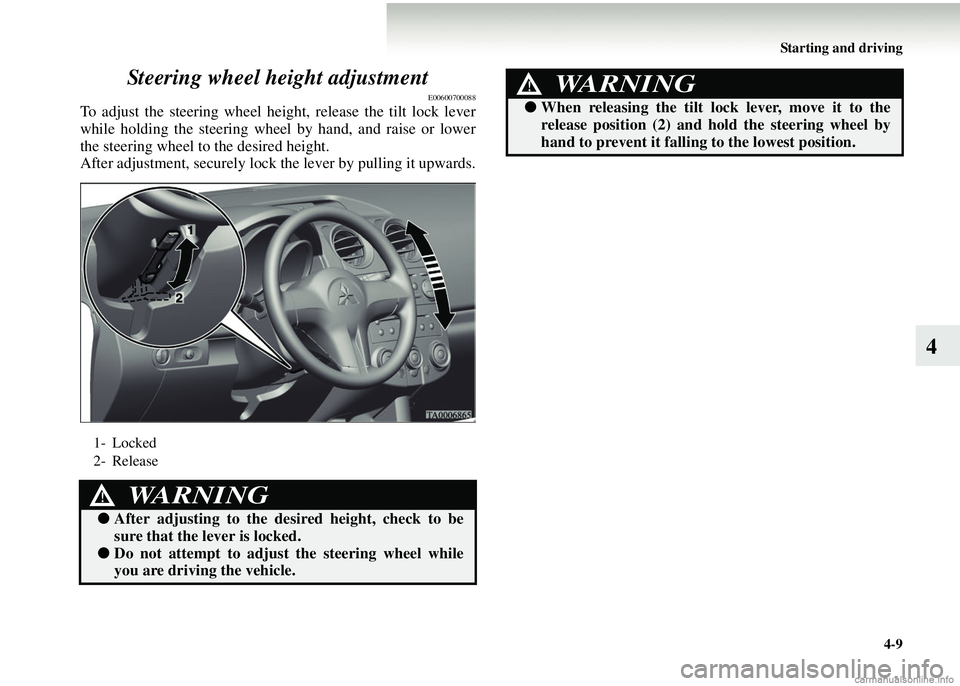
To adjust the steering wheel height, release the tilt lock lever
while holding the steering wheel by hand, and raise or lower
the steering wheel to the desired height.
After adjustment, securely lock the lever by pulling it upwards.
1- Locked
2- Release
WARNING!
●
After adjusting to the desired height, check to be
sure that the lever is locked.
●Do not attempt to adjust the steering wheel while
you are drivin g the vehicle.
●When releasing the tilt lock lever, move it to the
release position (2) and hold the steering wheel by
hand to prevent it falling to the lowest position.
WARNING!
Page 176 of 450
4-10 Starting and driving
4Inside rear-view mirror
E00600800047
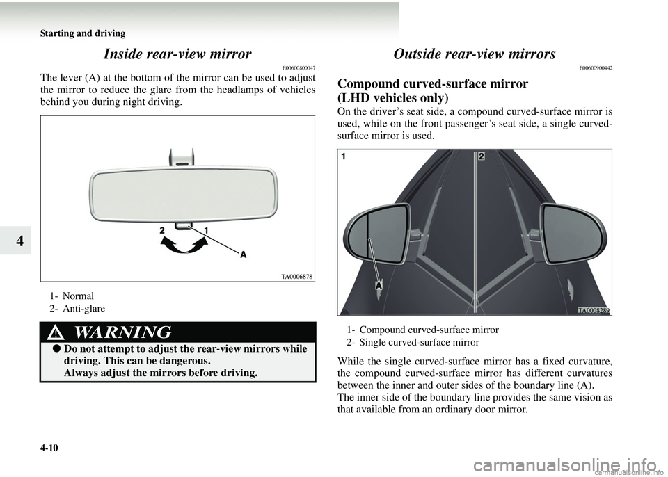
The lever (A) at the bottom of th
e mirror can be used to adjust
the mirror to reduce the glare from the headlamps of vehicles
behind you during night driving.
Outside rear-view mirrors
E00600900442
Compound curved-surface mirror
(LHD vehicles only)
On the driver’s seat side, a co mpound curved-surface mirror is
used, while on the front passenger’s seat side, a single curved-
surface mirror is used.
While the single curved-surface mirror has a fixed curvature,
the compound curved-surface mirror has different curvatures
between the inner and outer sides of the boundary line (A).
The inner side of the boundary line provides the same vision as
that available from an ordinary door mirror.
1- Normal
2- Anti-glare
WARNING!
● Do not attempt to adjust the rear-view mirrors while
driving. This can be dangerous.
Always adjust the mirrors before driving.
1- Compound curved-surface mirror
2- Single curved-surface mirror
Page 177 of 450
Starting and driving4-11
4
However, the outer side of the boundary line provides a wider
vision than an ordinary door mirror.
To adjust the mirror positionE00601000147
Manual remote-controlled ou tside rear-view mirrors*
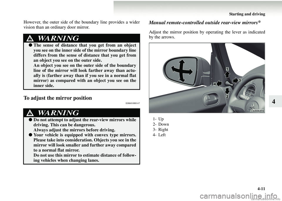
Adjust the mirror position by operating the lever as indicated
by the arrows.
WARNING!
●The sense of distance that you get from an object
you see on the inner side of the mirror boundary line
differs from the sense of distance that you get from
an object you see on the outer side.
An object you see on the outer side of the boundary
line of the mirror will lo ok farther away than actu-
ally is (farther away than if you see in a normal flat
mirror) as compared with an object you see on the
inner side.
WARNING!
● Do not attempt to adjust the rear-view mirrors while
driving. This can be dangerous.
Always adjust the mirrors before driving.
●Your vehicle is equipped with convex type mirrors.
Please take into considerati on. Objects you see in the
mirror will look smaller and further away compared
to a normal flat mirror.
Do not use this mirror to estimate distance of follow-
ing vehicles when changing lanes.
1- Up
2- Down
3- Right
4- Left
Page 178 of 450
4-12 Starting and driving
4
Electric remote-controlled outside rear-view mirrors*E00610900041
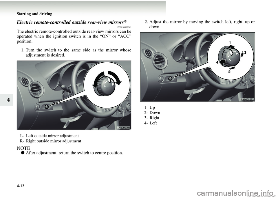
The electric remote-controlled out side rear-view mirrors can be
operated when the ignition switch is in the “ON” or “ACC”
position.
1. Turn the switch to the same side as the mirror whose adjustment is desired.
NOTE● After adjustment, return the switch to centre position. 2. Adjust the mirror by moving the switch left, right, up or
down.
L- Left outside mirror adjustment
R- Right outside mirror adjustment
1- Up
2- Down
3- Right
4- Left
Page 179 of 450
Starting and driving4-13
4
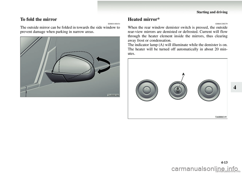
To fold the mirrorE00601100454
The outside mirror can be folded in towards the side window to
prevent damage when parking in narrow areas.
Heated mirror*E00601200279
When the rear window demister switch is pressed, the outside
rear-view mirrors are demisted or defrosted. Current will flow
through the heater element insi de the mirrors, thus clearing
away frost or condensation.
The indicator lamp (A) will illuminate while the demister is on.
The heater will be turned off automatically in about 20 min-
utes.
Page 180 of 450
4-14 Starting and driving
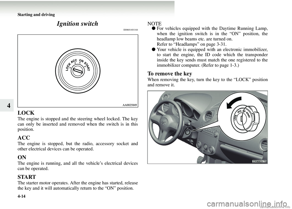
4Ignition switch
E00601401164
LOCK
The engine is stopped and the
steering wheel locked. The key
can only be inserted and removed when the switch is in this
position.
ACC
The engine is stopped, but th e radio, accessory socket and
other electrical devices can be operated.
ON
The engine is running, and all the vehicle’s electrical devices
can be operated.
START
The starter motor operates. After the engine has started, release
the key and it will automatically return to the “ON” position.
NOTE● For vehicles equipped with the Daytime Running Lamp,
when the ignition switch is in the “ON” position, the
headlamp low beams etc. are turned on.
Refer to “Headlamps” on page 3-31.
● Your vehicle is equipped with an electronic immobilizer,
to start the engine, the ID code which the transponder
inside the key sends must match the one registered to the
immobilizer computer. (Refer to page 1-3.)
To remove the key
When removing the key, turn the key to the “LOCK” position
and remove it.