recommended oil MITSUBISHI DIAMANTE 1900 User Guide
[x] Cancel search | Manufacturer: MITSUBISHI, Model Year: 1900, Model line: DIAMANTE, Model: MITSUBISHI DIAMANTE 1900Pages: 408, PDF Size: 71.03 MB
Page 81 of 408
.
3-20 ENGINEANDENGINEOVERHAUL
Never open, service or drain the radiator or
cooling system when hot; serious burns can
occur from the steam and hot coolant. Also,
when draining engine coolant, keep in mind
that cats and dogs are attracted to ethylene
glycol antifreeze and could drink any that is
left in an uncovered container or in puddles
on the ground. This will prove fatal in suffi-
cient quantities. Always drain coolant into a
sealable container. Coolant should be reused
unless it is contaminated or is several years
old.
3. Remove the overflow hose and disconnect
the upper radiator hose.
*It is recommended that each clamp be
matchmarked to the hose. Observe the marks
and reinstall the clamps exactly when rein-
stalling the radiator.
4. If equipped with an automatic transaxle, re-
move and plug the fluid cooler hoses.
5. Unplug the electrical connector(s) from the
coolant fan motor.
6. Remove the mounting bolts, then remove the
fan and shroud assembly from the vehicle.
7. Remove the fan blade retainer nut from the
shaft on the fan motor and separate the fan from the
motor.
8. Remove the motor to shroud attaching
screws and the motor from the shroud.
To tnstall: 9. Install the motor to the shroud and secure
with the mounting bolts.
10. Install the remaining components in the re-
verse order of removal.
11. Fill the coohng system. Connect the negative
battery cable and check the cooling fan for proper op-
eration.
Diamante
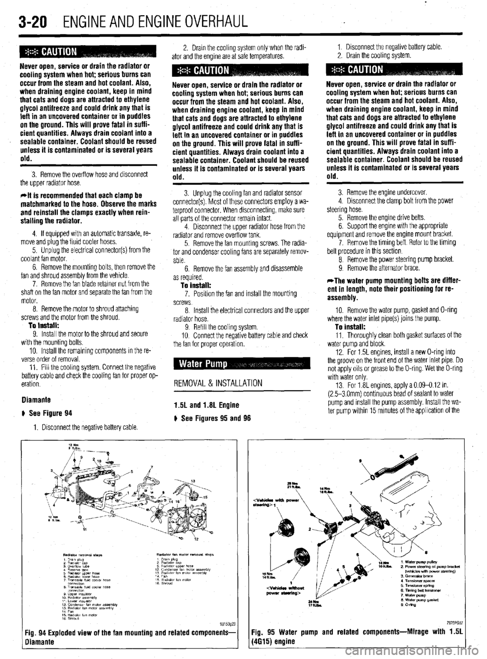
# See Figure 94
1. Disconnect the negative battery cable 2. Drain the cooling system only when the radi-
ator and the engine are at safe temperatures. 1. Disconnect the negative battery cable
2. Drain the cooling system.
Never open, service or drain the radiator or
cooling system when hot; serious burns can
occur from the steam and hot coolant. Also,
when draining engine coolant, keep in mind
that cats and dogs are attracted to ethylene
glycol antifreeze and could drink any that is
left in an uncovered container or in puddles
on the ground. This will prove fatal in suffi-
cient quantities. Always drain coolant into a
sealable container. Coolant should be reused
unless it is contaminated or is several years
old.
3. Unplug the cooling fan and radiator sensor
connector(s). Most of these connectors employ a wa-
terproof connector. When disconnecting, make sure
all parts of the connector remain intact.
4. Disconnect the upper radiator hose from the
radiator and remove overflow tank.
5. Remove the fan mounting screws. The radia-
tor and condenser cooling fans are separately remov-
able.
6. Remove the fan assembly and disassemble
Never open, service or drain the radiator or
cooling system when hot; serious burns can
occur from the steam and hot coolant. Also,
when draining engine coolant, keep in mind
that cats and dogs are attracted to ethylene
glycol antifreeze and could drink any that is
left in an uncovered container or in puddles
on the ground. This will prove fatal in suffi-
cient quantities. Always drain coolant into a
sealable container. Coolant should be reused
unless it is contaminated or is several years
old.
3. Remove the engine undercover.
4 Disconnect the clamp bolt from the power
steering hose.
5. Remove the engine drive belts.
6. Support the engine with the appropriate
equipment and remove the engine mount bracket.
7. Remove the timing belt Reier to the timing
belt procedure in this section
8 Remove the power steering pump bracket.
9. Remove the alternator brace.
as required.
To install: 7. Posrtion the fan and install the mounting
screws
*The water pump mounting bolts are differ-
ent in length, note their positioning for re-
assembly.
8 Install the electrical connectors and the upper
radiator hose.
9. Refill the cooling system.
IO. Connect the negative battery cable and check
the fan for orooer ooeration. 10. Remove the water pump, gasket and O-ring
where the water inlet pipe(s) joins the pump.
To install: 11, Thoroughly clean both gasket surfaces of the
water oumo and block.
12. For 1.5L engines, install a new O-ring into
the groove on the front end of the water inlet pipe. Do
not apply oils or grease to the O-ring. Wet the O-ring
with water only
13. For 1.8L engines, apply a 0.09-0.12 in.
(2.5-3 Omm) continuous bead of sealant to water
pump and rnstall the pump assembly. Install the wa-
ter pump within 15 minutes of the applrcation of the
REMOVAL & INSTALLATION
1.5L and 1.8L Engine
) See Figures 95 and 98
7923PGO :ig. 94 Exploded view of the fan mounting and related components- Fig. 95 Water pump and related components-Mirage with 1.51
liamante (4615) engine
Page 87 of 408
3-26 ENGINEANDENGINEOVERHAUL
18. Remove the self-locking nuts and the small
retaining bolt holding the exhaust pipe to the bottom
of the exhaust manifold. Separate the pipe from the
manifold and remove the gasket.
19. Remove the bolts holding the support brace
to the bottom of the intake manifold.
20. Use the special hex wrench (MB 998051-01)
and loosen the head bolts in the order shown in 2 or
3 passes. When all are finger loose, remove the bolts.
21. Rock the head gently to break it loose; if tap-
ping is necessary, do so with a rubber or wooden
mallet at the corners of the head. DO NOT pry the
head up by wedging tools between the head and the
block.
22. Lift the head free of the engine. It is coming
off with both manifolds and the intake plenum at-
tached; the help of an assistant is recommended for
lifting. Support the head assembly on wooden blocks
on a suitable workbench. Refer to Cleaning and In-
spection in this section for work to be done before in-
stalling the head. If the head has been removed for
work other than gasket replacement, the rocker as-
sembly and camshaft or other components may be
removed.
Before reinstallation, the head should be com-
pletely assembled on the bench. This allows proper
location and tightening of all the external items.
To install: 23. Place a new gasket on the engine so that the
identifying mark faces up (towards the head) and is at
the timing belt end of the block. Install a new gasket
on the exhaust pipe.
Do not apply sealant to the head gasket or
mating surfaces.
24. Install the head straight down onto the block.
Try to eliminate most of the side-to-side adjust-
ments as this may move the gasket out of position.
Install the bolts by hand and just start each bolt 1 or
2 turns on the threads.
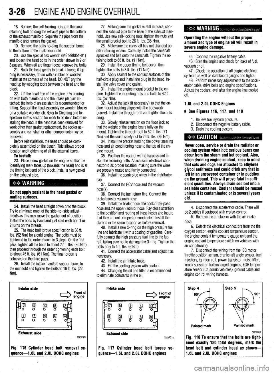
25. The head bolt torque specification is 68 ft.
Ibs. (92 Nm) for a cold engine. The bolts must be
tightened in the order shown in 3 steps. On the first
pass, tighten all the bolts to about 22 ft. Ibs. (30 Nm),
then proceed through the order tightening each bolt
to about 45 ft. Ibs. (61 Nm). The final torque is
achieved on the third pass.
26. Install the intake manifold support brace to
the manifold and tighten the bolts to 16 ft. Ibs. (22
Nm). 27. Making sure the gasket is still in place, con-
nect the exhaust pipe to the base of the exhaust man-
ifold. Use new self-locking nuts; tighten the nuts and
the small bracket bolt to 26 ft. Ibs. (35 Nm).
28. Make sure the camshaft has not changed po-
sition during repalrs. Carefully install the camshaft
sprocket and belt onto the camshaft. Tighten the re-
taining bolt to 66 ft. Ibs. (91 Nm).
29. Install the upper timing belt cover, then
tighten the bolts to 8 ft. Ibs. (11 Nm).
30. Apply sealant to the contact surfaces of the
half-circle plug and install the plug in the head In-
stall the valve cover and gasket.
31. Install the engine mount bracket to the en-
gine. Tighten the mounting nuts and bolts to 42 ft.
Ibs. (57 Nm).
32. Adjust the jack (if necessary) so that the en-
gine mount bushing aligns with the bodywork
bracket. Install the through-bolt and tighten the nuts
snug.
33. Slowly release tension on the floor jack so
that the weight of the engine bears fully on the
mount. Tighten the through-bolt to 52 ft. Ibs. (71
Nm) and the small safety nut to 26 ft. tbs. (36 Nm).
34. Install the bracket holding the power steering
hose and air conditioning hose to the top of the en-
gine mount.
35. Position the control wiring harness and in-
stall the retaining bolts. Attach each electrical con-
nector to its proper location, making sure the wires
are properly routed and firmly connected.
36. Install the spark plug wires in the distributor
cap.
37. Connect the PCV hose and the vacuum
hose(s).
38. Connect the fuel return line. Connect the
brake booster vacuum hose.
39. Install the heater hose, the coolant by-pass
hose and.the upper radiator hose. Pay close attention
to the position and routing of these hoses and insure
that they are not crimped or constricted. Install the
clamps in the same location as before removal.
40. Install a new O-ring on the high pressure fuel
line and lubricate it with a coating of gasoline. Care-
fully connect the high pressure fuel line to the fuel
rail, taking care not to damage the O-ring. Tighten the
bolts only to 4 ft. Ibs. (6 Nm).
41. Connect the accelerator cable and adjust it as
necessary.
42. Install the air intake hose.
43. Fill the cooling system with coolant.
44. Changing the oil and filter is recommended
to eliminate pollutants in the oil.
Intake side
I Front of
engine
Exhaust side
Fig. 116 Cylinder head bolt removal se-
quence-l .6L and 2.OL DDHC engines intake
side
Front of
entine
Exhaust side 7923PG18
Fig. 117 Cylinder head bolt torque se-
quence-l .6L and 2.OL DDHC engines Operating the engine without the proper
amount and type of engine oil will result in
severe engine damage.
45. Connect the negative battery cable.
46. Start the engine and check for leaks of fuel,
vacuum or oil.
47. Check the operation of all engine electrical
systems as well as dashboard gauges and lights.
48. Perform necessary adjustments to the accel-
erator cable, drive belts and engine specifications.
Adjust the coolant level after the engine has cooled
Off.
1.6L and 2.OL DDHC Engines
ti See Figures 116,117, and 116
1. Relieve fuel system pressure.
2. Disconnect the negative battery cable.
3. Drain the cooling system.
Never open, service or drain the radiator or
cooling system when hot; serious burns can
occur from the steam and hot coolant. Also,
when draining engine coolant, keep in mind
that cats and dogs are attracted to ethylene
glycol antifreeze and could drink any that is
left in an uncovered container or in puddles
on the ground. This will prove fatal in suffi-
cient quantities. Always drain coolant into a
sealable container. Coolant should be reused
unless it is contaminated or is several years
old.
4. Disconnect the accelerator cable. There will
be 2 cables if equipped with cruise-control.
5. Remove the air cleaner with the air intake
hose.
6. Detach the electrical connectors from the the
oxygen sensor, engine coolant temperature sensor,
the engine coolant temperature gauge unit and the
engine coolant temperature switch on vehicles with
air conditioning.
7. Disconnect the wiring from the ISC motor,
throttle position sensor, crankshaft angle sensor, fuel
injectors, ignition coil, power transistor, noise filter,
knock sensor on turbocharged engines, EGR temper-
ature sensor (California vehicles), ground cable and
engine control wiring harness.
Painted mark Painted mark
Fig. 116 To ensure that the bolts are tight-
ened exactly 160 total degrees, mark the
11.6L and 2.OL DDHC engines head bolt and cylinder head as shown-
Page 109 of 408
.
3-48 ENGINEANDENGINEOVERHAUL
32. Install the crankshaft pulley if it was removed.
Tighten the bolt to 110 ft. Ibs. (150 Nm).
33. Install the air conditioning bracket and com-
pressor on the engine. Install the belt tensioner.
34. Install the power steering pump into position.
Install the fan pulley and fan.
35. Install the fan shroud on the radiator.
36. Refill the cooling system.
I
37. Connect the negative battery cable.
38. Start the enaine and check for fluid leaks.
Fig. 188 CI ’ m
belt neeK ror premature panrng of the
Fig. 189 Check if the teeth are cracked or
IUIIII~U at IWSI
arly me me upper ommg oerr cover 1 1 damaged ,
I
is off. If the timina belt shows anv sians of failure. it INSPECTION
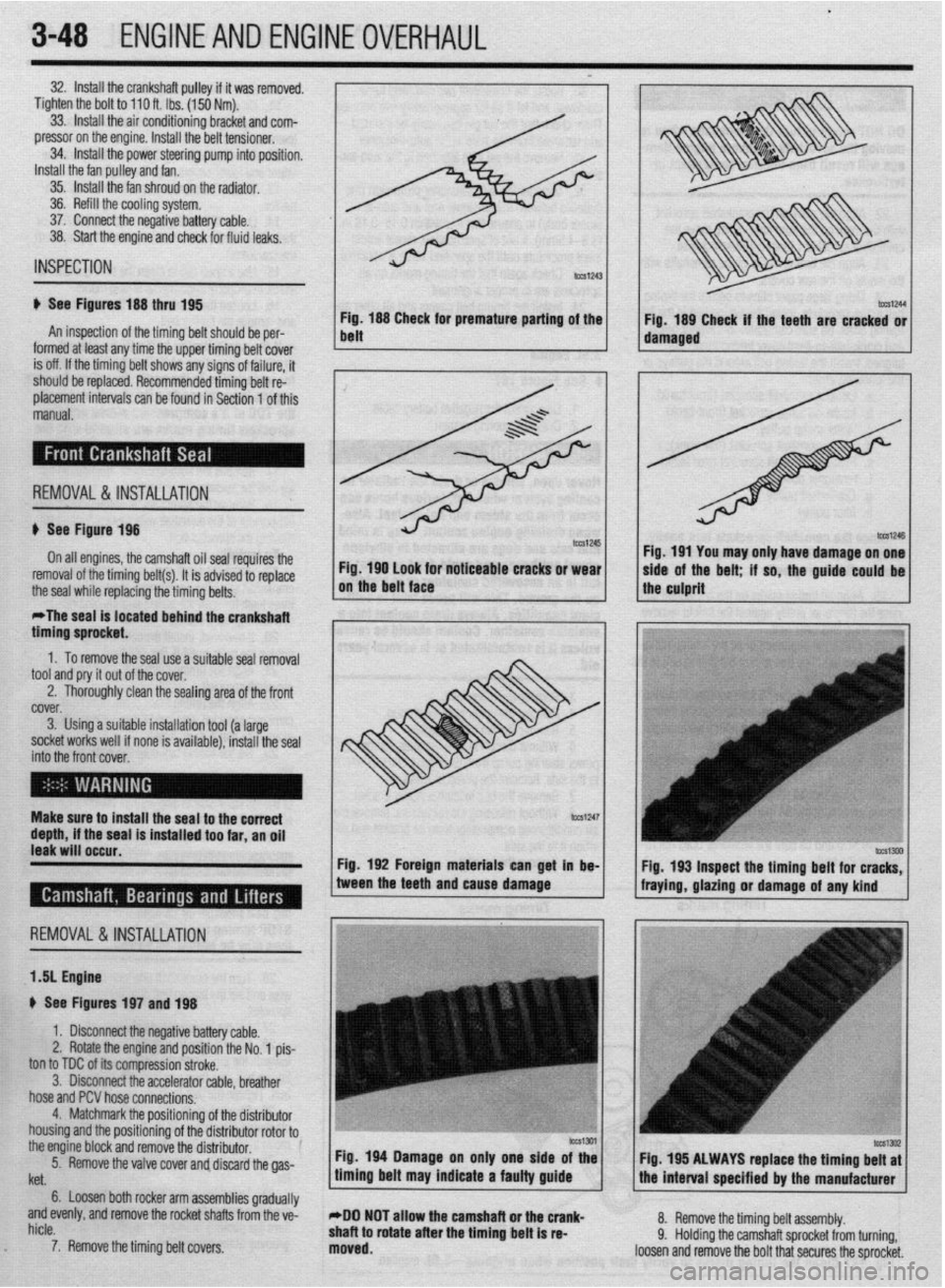
ti See Figures 188 thru 195
An inspection of the timing belt should be per-
I ^__^ -I ^I I---.-- I.-. II. .- I. . I I.
should be replaced. Recommended timing belt re:
placement intervals can be found in Section 1 of this
manual.
; REMOVAL&INSTALLATION
u See Figure 198
On all engines, the camshaft oil seal repuires the
Fig. 190 look for noticeable cracks or wear
removal of the timing belt(s). It is advised to replace
the seal while replacing the timing belts. on the belt face
*The seal is located behind the crankshaft
timino sorocket. I I Fig. 191 You may only have damage on one
side of the belt; if so, the guide-could be 1
the culprit
” .
1. To remove the seal use a suitable seal removal
tool and pry it out of the cover.
2. Thoroughly clean the sealing area of the front
fYi”f.V
i ““.“I. 3. Using a suitable installation tool (a large
socket works well if none is available), install the seal
into thr ? front cover,
EnI
Make surf! to install the seal to the correct
depth, if the seal is installed too far, an oil
leak will occur.
Fig. 192 Foreign materials can get in be-
REMOVAL &INSTALLATION
1 .!I Engine
+ See Figures 197 and 198
1. Disconnect the negative battery cable.
2. Rotate the engine and position the No. 1 pis-
ton to TDC of its compression stroke.
3. Disconnect the accelerator cable, breather
hose and PCV hose connections.
4. Matchmark the positionino of the distributor
housing and the positioning of thedistributor rotor to0
the engine block and remove the distributor.
5.
. Remove the valve cover and discard the gas- tween the teeth and cause damage
fraying, gla&g or damage of any kind
’
Itet.
6. Loosen both rocker arm assemblies gradually
and evenly, and remove the rocket shafts from the ve-
hicle.
7. Remove the timing belt covers.
c
Fig 194 Damage on only one side of the
timing belt may indicate a faulty guide Fig. 195 ALWAYS raplace the timing belt at
the interval soecified br the manufacturer
*DO NOT allow the camshaft or the crank-
shaft to rotate after the timing belt is re-
moved. 8. Remove the timing belt assembly.
9. Holding the camshaft sprocket from turning,
loosen and remove the bolt that secures the sprocket.
Page 112 of 408
ENGlNEANDENGlNEOVERHALiL 3-51
:ig. 203 Camshaft, rocker arm and shaft assemblies-2.41 engine 9315393'
Intake side Exhaust side
7923PG57 Fig. 204 Camshaft identification-2.41 en-
gine
9. Remove the intake and exhaust camshafts.
10. Remove the rocker arms and lash adjusters
*It is essential that all parts be kept in the
same order and orientation for reinstallation.
In order to prevent confusion during installa-
tion, be sure to mark and separate all parts.
To install:
11. Install the lash adjusters and rocker arms into
the cylinder head. Lubricate lightly with clean oil
prior to installation.
12. Lubricate the camshafts with heavy engine oil
and position the camshafts on the cylinder head.
13 Check the camshaft journals and lobes for
wear or damage. Also, check the cylinder head oil
holes for clogging. Visually inspect the rocker arm
roller and replace if dented, damaged or evidence of
seizure is evident. Check the roller for smooth rota-
tion. Replace If excess play or binding is present.
Also, inspect the valve contact surface for possible
damage or seizure. It is recommended that all rocker
arms and lash adjusters be replaced together.
*Do not confuse the intake camshaft with
the exhaust camshaft. The intake camshaft
has a split on the rear face for driving the ,
crank angle sensor.
14. Make sure the dowel pin on both camshaft
sprocket ends are located on the top.
15. Install the bearing caps. Tighten the caps in
sequence and rn 2 or 3 steps. No 2 and 5 caps are of
the same shape. Check the markings on the caps to
identify the cap number and intake/exhaust symbol. Only 1 (intake) or I? (exhaust) is stamped on No. 1
bearing cap Also, make sure the rocker arm is cor-
rectly mounted on the lash adjuster and the valve
stem end. Torque the retaining bolts to 15 ft. Ibs. (20
Nm).
16. Apply a coating of engine oil to the oil seal.
Using the proper size driver, press-fit the seal into
the cylinder head.
17. Install the camshaft sprockets. While holding
the camshaft at its hexagon, between number 2 and 3
journals tighten sprocket bolts to 58-72 ft. Ibs.
(80-l 00 Nm).
18. Install the timing belt, covers and related
components.
19. Install the valve cover, using new gasket, and
reconnect all related components
20. Reconnect the negative battery cable.
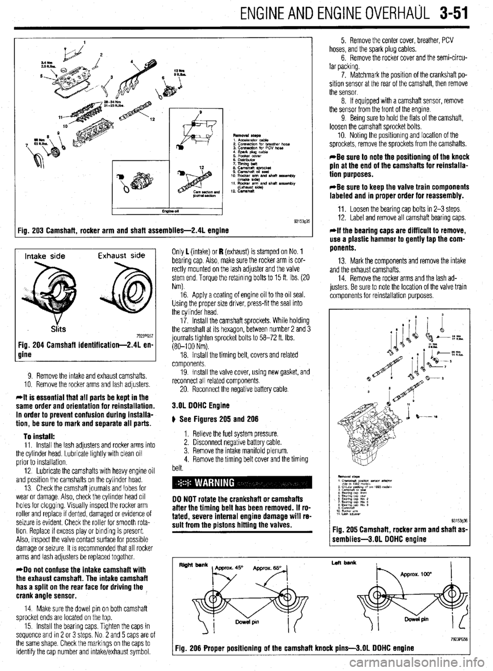
3.OL DOHC Engine
# See Figures 205 and 206
1. Relieve the fuel system pressure.
2. Disconnect negative battery cable.
3. Remove the intake manifold plenum.
4. Remove the timing belt cover and the timing
belt.
DO NOT rotate the crankshaft or camshafts
after the timing belt has been removed. If ro-
tated, severe internal engine damage will re-
sult from the pistons hitting the valves.
5. Remove the center cover, breather, PCV
hoses, and the spark plug cables.
6. Remove the rocker cover and the semi-circu-
lar packing.
7. Matchmark the position of the crankshaft po-
sition sensor at the rear of the camshaft, then remove
the sensor.
8. If equipped with a camshaft sensor, remove
the sensor from the front of the engine.
9 Being sure to hold the flats of the camshaft,
loosen the camshaft sprocket bolts.
10. Noting the positionmg and location of the
sprockets, remove the sprockets from the camshafts.
*Be sure to note the positioning of the knock
pin at the end of the camshafts for reinstalla-
tion purposes.
*Be sure to keep the valve train components
labeled and in proper order for reassembly.
11. Loosen the bearing cap bolts in 2-3 steps.
12. Label and remove all camshaft bearing caps.
*If the bearing caps are difficult to remove,
use a plastic hammer to gently tap the com-
ponents.
13. Mark the components and remove the intake
and the exhaust camshafts.
14. Remove the rocker arms and the lash ad-
justers. Be sure to note the location of the valve train
components for reinstallation purposes.
1 semblies-3.01 DOHC engine
I
Left bank
7923PG58 Fig. 206 Proper positioning of the camshaft knock pins-3.01 DOHC engine
Page 116 of 408
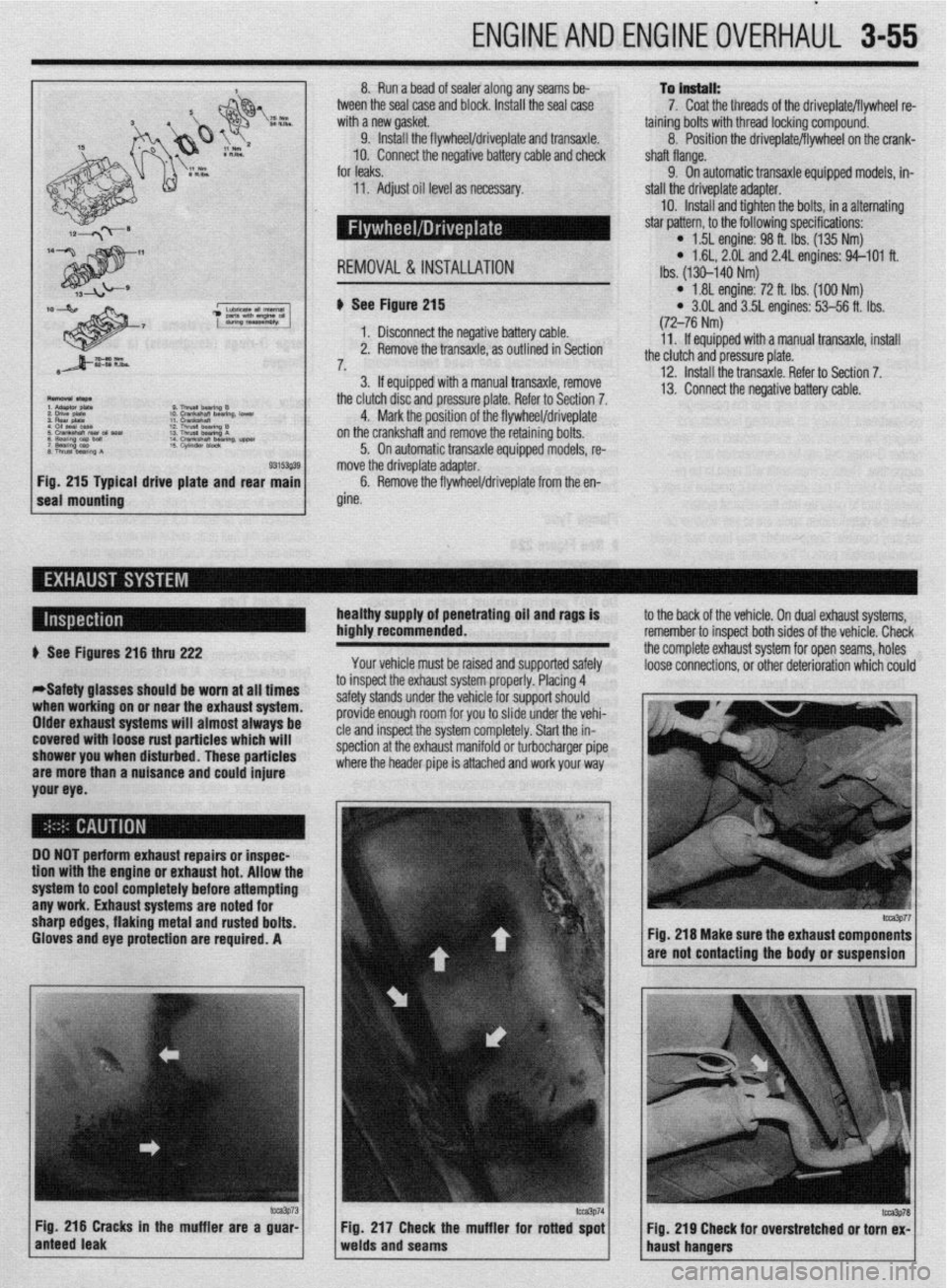
ENGINEANDENGINEOVERHAUL 3-55
8. Run a bead of sealer along any seams be-
tween the seal case and block. Install the seal case
with a new gasket.
9. Install the flywheel/driveplate and transaxle.
10. Connect the negative battery cable and check
for leaks.
11. Adjust oil level as necessary.
REMOVAL &INSTALLATION To lnstell:
7. Coat the threads of the driveplate/flywheel re-
taining bolts with thread locking compound.
8. Position the driveplatelflywheel on the crank-
shaft flange.
9. On automatic transaxle equipped models, in-
stall the driveplate adapter.
10. Install and tighten the bolts, in a alternating
star pattern, to the following specifications:
l 1.5L engine: 98 ft. Ibs. (135 Nm) l 1.6L, 2.01 and 2.4L engines: 94-101 ft.
Ibs. (130-140 Nm)
al drive plate and rear b See Figure 215
1. Disconnect the negative battery cable.
2. Remove the transaxle, as outlined in Section
7,
3. If equipped with a manual transaxle, remove
the clutch disc and pressure plate. Refer to Section 7.
4. Mark the position of the flywheel/driveplate
on the crankshaft and remove the retaining bolts.
5. On automatic transaxle equipped models, re-
move the driveplate adapter.
6. Remove the flywheel/driveplate from the en-
gine.
l 1.81 engine: 72 ft. Ibs. (100 Nm) l 3.OL and 3.5L engines: 53-56 ft. Ibs.
(72-76 Nm)
11. If equipped with a manual transaxle, install
the clutch and pressure plate.
12. Install the transaxle. Refer to Section 7.
13. Connect the negative battery cable.
healthy supply of penetrating oil and rags is
highly recommended.
Your vehicle must be raised and supported safely to the back of the vehicle. On dual exhaust systems,
remember to insoect both sides of the vehicle. Check
the complete exhaust system for open seams, holes
loose connections, or other deterioration which could + See Figures 216 thru 222
*Safety glasses should be worn at all times
when working on or near the exhaust system.
Older exhaust systems will almost always be
covered with loose rust particles which will
shower you when disturbed. These particles
are more than a nuisance and could injure
your eye. to inspect the exhaust system properly. Placing 4
safety stands under the vehicle for support should
provide enough room for you to slide under the vehi-
cle and inspect the system completely. Start the in-
spection at the exhaust manifold or turbocharger pipe
where the header pipe is attached and work your way
DO NOT perform exhaust repairs or inspec-
tion wtth the engine or exhaust hot. Allow thr
system to cool completely before attempting
any work. Exhaust systems are noted for
sharp edges, flaking metal and rusted bolts.
Gloves and eye protection are required. A
m3p73 Fig. 216 Cracks in the muffler are a guar-
anteed leak Fig 217 Check the muffler for rotted spot
Fig. 219 Cheek for overstretched or torn ex-
welds and seams
haust hangers
fm3p77 Fig. 216 Make sure the exhaust components
are not contacting the body or suspension
lcca3P78
Page 117 of 408
3-56 ENGINEANDENGINEOVERHAUL
,
F C
F
t
. Fig.
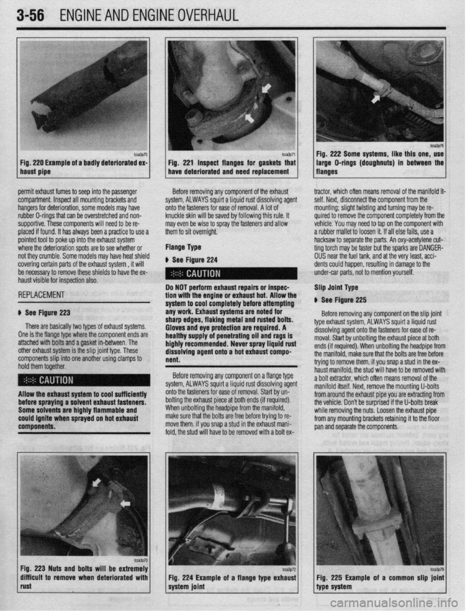
220 Example of a badly deteriorated ex- 1 Fig. 221 inspect flanges for gaskets that
haust pipe have deteriorated and need replacement Fig. 222 Some systems, like this one, use
)ermit exhaust fumes to seep into the passenger
:ompartment. Inspect all mounting brackets and
bangers for deterioration, some models may have
ubber O-rings that can be overstretched and non-
supportive. These components will need to be re-
Ilaced if found. It has always been a practice to use a
)ointed tool to poke up into the exhaist system
vhere the deterioration spots are to see whether or
d they crumble. Some models may have heat shield
:overing certain parts of the exhaust system , it will
te necessary to remove these shields to have the ex-
laust visible for inspection also. Before removing any component of the exhaust
system, ALWAYS squirt a Liquid rust dissolving agent
onto the fasteners for ease of removal. A lot of
knuckle skin will be saved by following this rule. It
may even be wise to spray the fasteners and allow
them to sit overniqht.
Flange Type
b See Figure 224 tractor, which oflen means removal of the manifold it
self. Next, disconnect the component from the
mounting; slight twisting and turning may be re-
quired to remove the component completely from thr
vehicle. You may need to tap on the component with
a rubber mallet to loosen it. If all else fails, use a
hacksaw to sep; arate the parts. An oxy-acetylene cut-
ting torch may I 3e faster but the sparks are OANGER-
OUS near the fuel tank, ant 1 at the very least, acci-
dents could happen, result ing in damage to the
under-car parts, not to mei ition yourself.
3EPLACEMEMT
1 See Figure 223
There are basically two types of exhaust systems.
)ne is the flange type where the component ends are
attached with bolts and a gasket in-between. The
)ther exhaust system is the slip joint type. These
:omponents slip into one another using clamps to
iold them together. Do NOT perform exhaust repairs or inspec-
tion with the engine or exhaust hot. Allow the
system to cool completely before attempting
any work. Exhaust systems are noted for
sharp edges, flaking metal and rusted bolts.
Gloves and eye protection are required. A
healthy supply of penetrating oil and
rags is
highly recommended. Never spray liquid rust
dissolving agent onto a hot exhaust compo-
nent. Slip Joint Type
V See Figure 225
Before removing any component on the slip joint
type exhaust system, ALWAYS squirt a liquid rust
dissolving agent onto the fasteners for ease of re-
moval. Start by unbolting the exhaust piece at both
ends (if required). When unbolting the headpipe fron
the manifold, make sure that the bolts are free before
trying to remove them. if you snap a stud in the ex-
haust manifold. the stud will have to be removed wit1
Before removing any component on a flange type
system, ALWAYS squirt a liquid rust dissolving agent a bolt extractor, which often means removal of the
._ manifold itself. Next. remove the mountina U-bolts
liiow the exhaust system to cool sufficiently
Iefore spraying a solvent exhaust fasteners.
Some solvents are highly flammable and
:ould ignite when sprayed on hot exhauti
:omponents. onto the fasteners for ease of removal. Start by un-
bolting the exhaust piece at both ends (if required).
When unbolting the headpipe from the manifold,
make sure that the bolts are free before trying to re-
move them. if you snap a stud in the exhaust mani-
fold, the stud will have to be removed with a bolt ex-
ka3p70 Fig. 223 Nuts and bolts will be extremely
difflcuit to remove when deteriorated with
rust Fig. 224 Example of a flange type exhaust
system joint from around the exhaust pipe you are ext&ting from
the vehicle. Don’t be surprised if the U-bolts break
while removing the nuts. Loosen the exhaust pipe
from any mounting brackets retaining it to the floor
pan and separate the components.
Fig. 225 Example of a common slip joini
type system
Page 119 of 408
3-58 ENGINEANDENGINEOVERHAUL '
*The editors at Chilton feel that most engine
machining should be performed by a profes-
sional machine shop. Don’t think of it as
wasting money, rather, as an assurance that
the job has been done right the first time.
There are many expensive and specialized
tools required to perform such tasks as bor-
ing and honing an engine block or having a
valve job done on a cylinder head. Even in-
specting the parts requires expensive mi-
crometers and gauges to properly measure
wear and clearances. Also, a machine shop
can deliver to you clean, and ready to as-
semble parts, saving you time and aggrava-
tion. Your maximum savings will come from
performing the removal, disassembly, as-
sembly and installation of the engine and
purchasing or renting only the tools required
to perform the above tasks. Depending on
the particular circumstances, you may save
40 to 60 percent of the cost doing these your-
self.
A complete rebuild or overhaul of an engine in-
volves replacing all of the moving parts (pistons,
rods, crankshaft, camshaft, etc.) with new ones and
machining the non-moving wearing surfaces of the
block and heads. Unfortunately, this may not be cost
effective. For instance, your crankshaft may have
been damaged or worn, but it can be machined un-
dersize for a minimal fee.
So, as you can see, you can replace everything in-
side the engine, but, it is wiser to replace only those
parts which are really needed, and, if possible, repair
the more expensive ones. Later in this section, we
will break the engine down into its two main compo-
nents: the cylinder head and the engine block. We
will discuss each component, and the recommended
parts to replace during a rebuild on each. spect the component, buy the necessary parts and OVERHAULTIPS
deliver these to a shop for actual machine work.
Much of the assembly work (crankshaft, bearings, Aluminum has become extremely popular for use
piston rods, and other components) is well within the in engines, due to its low weight. Observe the follow-
scope of the do-it-yourself mechanic’s tools and abil- ing precautions when handling aluminum parts:
ities. You will have to decide for yourself the depth of
l Never hot tank aluminum parts (the caustic hot
involvement you desire in an engine repair or rebuild. 6nk solution will eat the aluminum.
l Remove all aluminum parts (identification tag,
TOOLS etc.) from engine parts prior to the tanking.
l Always coat threads lightly with engine oil or
The tools required for an engine overhaul or parts
anti-seize compounds before installation, to prevent
replacement will depend on the depth of your in-
seizure.
volvement. With a few exceptions, they will be the
l Never overtighten bolts or spark plugs espe-
tools found in a mechanic’s tool kit (see Section 1 of
this manual). More in-depth work will require some cially in aluminum threads.
When assembling the engine, any parts that will
or all of the following:
be exposed to frictional contact must be prelubed to
l A dial indicator (reading in thousandths)
provide lubrication at initial start-up. Any product
mounted on a universal base
specifically formulated for this purpose can be used,
l Micrometers and telescope gauges
* Jaw and screw-type pullers but engine oil is not recommended as a prelube in
most cases.
‘ Scraper
When semi-permanent (locked, but removable) in-
l Valve spring compressor
stallation of bolts or nuts is desired, threads should l Ring groove cleaner l Piston ring expander and compressor be cleaned and coated with Loctite@ or another simi- l Ridge reamer , lar, commercial non-hardening sealant. l Cylinder hone or glaze breaker l Plastigage@ l Engine stand
The use of most of these tools is illustrated in
this section. Many can be rented for a one-time use
from a local parts jobber or tool supply house spe-
cializing in automotive work.
Occasionally, the use of special tools is called for.
See the information on Special Tools and the Safety
Notice in the front of this book before substituting
another tool. CLEANING
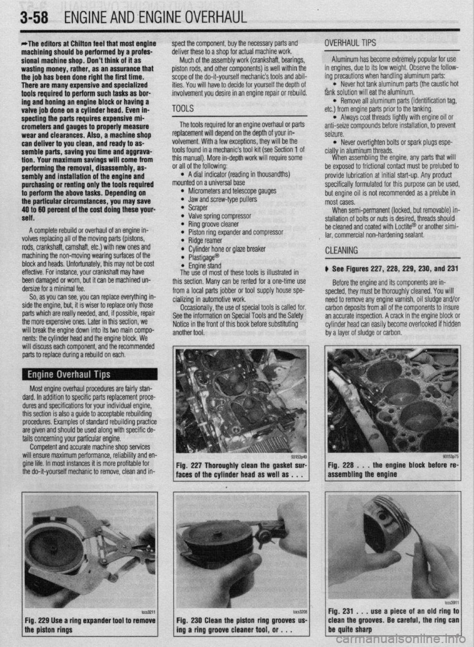
) See Figures 227, 228, 229, 230, and 231
Before the engine and its components are in-
spected, they must be thoroughly cleaned. You will
need to remove anv enaine varnish, oil sludoe and/or
c arbon deposits from ail of the componentsio insure
a In accurate inspection. A crack in the engine block or
c :ylinder head can easily become overlooked if hidden
t ry a layer of sludge or carbon.
Most engine overhaul procedures are fairly stan-
dard. In addition to specific parts replacement proce-
dures and specifications for your individual engine,
this section is also a guide to acceptable rebuilding
procedures. Examples of standard rebuilding practice
are given and should be used along with specific de-
tails concerning your particular engine.
Competent and accurate machine shop services
will ensure maximum performance, reliability and en-
gine life. In most instances it is more profitable for
the do-it-yourself mechanic to remove, clean and in- Fig. 227 Thoroughly clean the gasket sur-
faces of the cylinder head as well as . . .
Fig. 229 Use a ring expander tool to remove
the piston rings
fccs3911 ::“,z s,rpuse,a piece of fn old ring to 1
clean the grooves Be careful the ring can
230 Clean the piston ring grooves us-
ing a ring groove cleaner tool, or . . .
Page 120 of 408
ENGINEAND ENGINEOVERHAUL 3-59
Most of the cleaning process can be carried out
with common hand tools and readily available sol-
vents or solutions. Carbon deposits can be chipped
away using a hammer and a hard wooden chisel. Old
gasket material and varnish or sludge can usually be
removed using a scraper and/or cleaning solvent. Ex-
tremely stubborn deposits may require the use of a
power drill wrth a wire brush. If using a wire brush,
use extreme care around any critical machined sur-
faces (such as the gasket surfaces, bearing saddles,
cylinder bores, etc.). USE OF A WIRE BRUSH IS NOT
RECOMMENDED ON ANY ALUMINUM COMPO-
NENTS Always follow any safety recommendations
given by the manufacturer of the tool and/or solvent.
You should always wear eye protection during any
cleaning process involvrng scraping, chipping or
spraying of solvents.
An alternative to the mess and hassle of cleaning
the parts yourself is to drop them off at a local garage
or machine shop. They will, more than likely, have
the necessary equrpment to properly clean all of the
parts for a nominal fee.
Always wear eye protection during any clean-
ing process involving scraping, chipping or
spraying of solvents.
Remove any oil galley plugs, freeze plugs and/or
pressed-in bearings and carefully wash and degrease
all of the engine components including the fasteners
and bolts. Small parts such as the valves, springs,
etc., should be placed in a metal basket and allowed
to soak. Use pipe cleaner type brushes, and clean all
passageways in the components. Use a ring ex-
pander and remove the rings from the pistons. Clean
the piston ring grooves with a special tool or a piece
of broken ring Scrape the carbon off of the top of the
piston. You should never use a wire brush on the
pistons. After preparing all of the piston assemblies
in this manner, wash and degrease them again.
Use extreme care when cleaning around the
cylinder head valve seats. A mistake or slip
may cost you a new seat.
When cleaning the cylinder head, remove carbon
from the combustron chamber with the valves in-
stalled. This will avoid damaging the valve seats.
:ig. 234 Drill out the damaged threads with
he specified size bit. Be sure to drill corn.
rletely through the hole or to the bottom oi
I blind hole REPAIRING DAMAGEDTHREADS
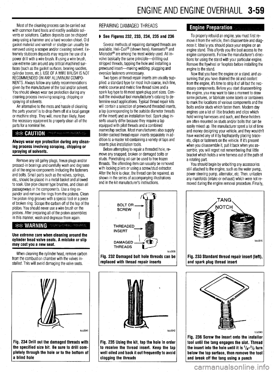
# See Figures 232, 233, 234, 235 and 236
Several methods of repairing damaged threads are
available Heli-Coil@ (shown here), Keenserts@ and
Microdop are among the most widely used. All in-
volve basically the same principle-drilling out
stripped threads, tapping the hole and installing a
prewound insert-making welding, plugging and
oversize fasteners unnecessary.
Two types of thread repair inserts are usually sup-
plied: a standard type for most inch coarse, rnch fine,
metric course and metrrc fine thread sizes and a
spark lug type to fit most spark plug port sizes. Con-
sult the individual tool manufacturers catalog to de-
termine exact applications. Typical thread repair kits
will contain a selection of prewound threaded inserts,
a tap (corresponding to the outside diameter threads
of the insert) and an installation tool. Spark plug in-
serts usually differ because they require a tap
equipped wrth pilot threads and a combined
reamer/tap section. Most manufacturers also supply
blister-packed thread repair Inserts separately in ad-
dition to a master kit containing a variety of taps and
inserts plus installation tools
Before attempting to repair a threaded hole, re-
move any snapped, broken or damaged bolts or
studs. Penetrating oil can be used to free frozen
threads. The offending item can usually be removed
with locking pliers or using a screw/stud extractor.
After the hole is clear, the thread can be reparred, as
shown in the series of accompanying illustrations
and in the krt manufacturers instructions.
THREADED
lCCS3039
replaced with thread repair inserts
:ig. 235 Using the kit, tap the hole in order
o receive the thread insert. Keep the tap
veil oiled and back it out frequently to avoid
:logging the threads
To properly rebuild an engine, you must first re-
move it from the vehicle, then disassemble and diag-
nose it. Ideally you should place your engine on an
engine stand. This affords you the best access to the
engine components. Follow the manufacturers direc-
tions for using the stand with your particular engine.
Remove the flywheel or flexplate before installing the
engine to the stand.
Now that you have the engine on a stand, and as-
suming that you have drained the oil and coolant
from the engine, it’s time to strip it of all but the nec-
essary components. Before you start disassembling
the engine, you may want to take a moment to draw
some pictures, or fabricate some labels or containers
to mark the locations of various components and the
bolts and/or studs which fasten them. Modern day
engines use a lot of little brackets and clips which
hold wiring harnesses and such, and these holders
are often mounted on studs and/or bolts that can be
easily mixed up. The manufacturer spent a lot of time
and money designing your vehicle, and they wouldn’t
have wasted any of it by haphazardly placing brack-
ets, clips or fasteners on the vehicle. If it’s present
when you disassemble it, put it back when you as-
semble, you will regret not remembering that little
bracket which holds a wire harness out of the path of
a rotating part.
You should begin by unbolting any accessories
still attached to the engine, such as the water pump,
power steering pump, alternator, etc. Then, unfasten
any manifolds (intake or exhaust) which were not re-
moved during the engine removal procedure. Finally,
Fig. 233 Standard thread repair insert (left),
and spark plug thread insert
im3043 Fig. 236 Screw the insert onto the installer
1001 until the tang engages the slot. Thread
‘he insert into the hole until it is l/4-l/~ turn
lelow the top surface, then remove the tool
and break off the tano usina a uunch
Page 124 of 408
ENGINEANDENGINEOVERHAUL 3-63
Place a straightedge across the gasket surface. Valves
Using feeler gauges, determine the clearance at the
center of the straightedge and across the cylinder Any valves that were not replaced should be
head at several points. Check along the centerline refaced and the tips ground flat. Unless you have ac-
and diagonally on the head surface. If the warpage cess to a valve grinding machine, this should be
exceeds 0.003 in. (0.076mm) within a 6.0 in. done by a machine shop. If the valves are in ex-
(152cm) span, or 0.006 in. (0.152mm) over the total tremely good condition, as well as the valve seats
length of the head, the cylinder head must be resur- and guides, they may be lapped in without petform-
,
I mg macnme worK.
4
It is a recnmmended practice to lap the valves faced. After resurfacing the heads of a V-type engine
the intake manifold flange surface should be checker,
and if necessary, milled proportionally to allow for
the change in its mounting position. _ - _ _ _ .- - - _
even after machine work has been p&formed and/or
new valves have been purchased. This insures a pos-
itive seal between the valve and seat.
-guide clearance; the 1
read
. .
into the cylinder head. Position the dial indicator
against the valve stem near the tie and zero the
gauge. Grasp the valve stem and’wiggle towards and
away from the dial indicator and observe the read-
ings. Mount the dial indicator 90 degrees from the
initial point and zero the gauge and again take a read-
ing. Compare the two readings for a out of round
condition. Check the readings against the specifica-
tions given. An Inside Diameter (I.D.) gauge designed
for valve guides will give you an accurate valve guide
bore measurement. If the I.D. gauge is used, compare
the readings with the specifications given. Any CRACKS AND PHYSICAL DAMAGE
Generally, cracks are limited to the combustion
chamber, hbwever, it is not uncommon for the head
to crack in a spark plug hole, port, outside of the
head or in the valve spring/rocker arm area. The first
area to inspect is always the hottest: the exhaust
.I *
seawpon area.
8 I .,“““I llly”Lv”l~ .ml”“l” - plr”llll”“, ““I ,“a’
because you don’t see a crack does not mean it is not
there. Some more reliable methods for inspecting for
cracks include Magnaflux? a magn$i,c process or
Zyglo? a dye penetrant. Ma{ -’
InatluxW IS used only on
ferrous metal (cast iron) heat Is. Zyglo@ uses a spray
on fluorescent mixture along with a black light to re-
veal the cracks. It is strongly recommended to have
your cylinder head checked professionally for cracks,
especially if the engine was known to have over-
I .* I,. ..^.. LAPPING THE VALVES
*Before iaoaino the valves to the seats,
read the rest of the cylinder head section to
insure that any related parts are in accept-
able enough condition to continue.
*Before anv valve seat machining and/or
lapping can be performed, the guides must
be within factory recommended specifica-
tions.
1. Invert the cylinder head.
2. Linhtlv Iuhrir;rB the valve stems and insert
-. _ ~ . . . . . .--.._-._
them into the cylinder head in their numbered order.
3. Raise the valve from the seat and apply a small
amount of fine lanninn compound to the seat.
4.
i guides that fail these inspections should be replaced nearea analor ieaKea or consumea coolant. Contact a Moisten the suction head of a hand-lapping
tool and attach it to the head of the valve.
i or machined. local shop for availability and pricing of these ser-
5. Rotate the tool between the palms of both
I vices.
I
VALVE SEATS Physical damage is usually very evident. For ex- hands, changing the position of the valve on the
valve seat and lifting the tool often to prevent groov-
A visual inspection of the valve seats should show
amnb P hrnbn mntlntinn ear from dropping the I and/or bolt. All of these ing.
.a,... . 6. Lap the valve until a smooth, polished circle is
a slightly worn and pitted surface where the valve
face contacts the seat. Inspect the seat carefully for
severe pitting or cracks. Also, a seat that is badly
worn will be recessed into the cylinder head. A se-
verely worn or recessed seat may need to be re- uetecIs SIIOUIO oe nxea or, IT unrepairaole, me neaa
should be replaced.
Camshaft and Followers evid
7
traces of the grinding corn
to maintain its lapped loca lent on the valve and seat.
‘. Remove the tool and the valve. Wipe away all
pound and store the valve
placed: All cracked seats must be replaced. A seat
concentricity gauge, if available, should be used to
check the seat run-out. If run-out exceeds specifica-
tions the seat must be machined (if no soecification
is given use 0.002 in. or O.O51mt$. Inspect the camshaft(s) and followers as described
earlier in this section.
REFINISHING & REPAIRING Do not get the valves out of order after they
have been lapped. They must be put back
: ..^^ I... --I:^:-L!-- --A
Many of the procedures gIveI
WI WIIIIISIIIIIIJ ~IIU repairing the cylinder head components must be per-
formed by a machine shop. Certain steps, if the in-
spected part is not worn, can be performed yourself
inexpensively. However, you spent a lot of time and
effort so far, why risk trying to save a couple bucks if
you might have to do it all over again?
I- with the same valve seat with which they
were lapped.
Springs, Retainers and Valve locks
There is no repair or refinishing possible with the
springs, retainers and valve locks. If they are found to
be worn or defective, they must be replaced with new
lor known nnod narts CYLtNDEt? HEAD SURFACE FLATNESS
) See Figures 256 and 257
After you have cleaned the gasket surface of the
cylinder head of any old gasket material, check the
head for flatness.
\- - a---r r- .-.
Cylinder Head
Most refinishing procedures dealing with the
VALVE GWDE
elf any machining or replacements are
e valve guides, the seats must be
Fig. 257 Checks should also be made along Unless the valve guides need machining or re-
placing, the only service to perform is to thoroughly‘
clean them of any dirt or oil residue.
Page 125 of 408
.
3-64 ENGINEANDENGINEOVERHAUL
There are only two types of valve guides used on
automobile engines: the replaceable-type (all alu-
minum heads) and the cast-in integral-type (most
cast iron heads). There are four recommended meth-
ods for repairing worn guides.
. Knurling
l Inserts l Reaming oversize l Replacing
Knurling is a process in which metal is displaced
and raised, thereby reducing clearance, giving a true
center, and providing oil control. It is the least ex-
pensive way of repairing the valve guides. However,
it is not necessarily the best, and in some cases, a
knurled valve guide will not stand up for more than
a short time. It requires a special knurlizer and pre-
cision reaming tools to obtain proper clearances. It
would not be cost effective to purchase these tools,
unless you plan on rebuilding several of the same
cylinder head.
Installing a guide insert involves machining the
guide to accept a bronze insert. One style is the coil-
type which is installed into a threaded guide. Another
is the thin-walled insert where the guide is reamed machined.
If the seats are in good condition, the valves can
be lapped to the seats, and the cylinder head assem-
bled. See the valves section for instructions on lap-
ping.
If the valve seats are worn, cracked or damaged,
they must be serviced by a machine shop. The valve
seat must be perfectly centered to the valve guide,
which requires very accurate machining.
CYLINDER HEAD SURFACE
If the cylinder head is warped, it must be ma-
chined flat. If the warpage is extremely severe, the
head may need to be replaced. In some instances, it
may be possible to straighten a warped head enough
to allow machining. In either case, contact a profes-
sional machine sh& for service. Cup Type Camshafl Followers
To install the springs, retainers and valve locks on
heads which have these components recessed into
the camshaft followers bore, you will need a small
I” .1.1.“1.“”
., ,, just after compressing the spring but before the *Any OHC cylinder head that shows exces-
sive warpage should have the camshaft bear-
ing journals align bored after the cylinder
head has been resurfaced. screwdriver-type tool, some clean white grease and a
lot of patience. You will also need the C-clamp style
spring compressor and the OHC tool used to disas-
semble the head.
1. Lightly lubricate the valve stems and insert all
of the valves into the cylinder head. If possible, main-
tain their original locations.
2. If equipped, install any valve spring shims
which were removed.
3. If equipped, install the new valve seals, keep-
ing the following in mind:
l If the valve seal presses over the guide,
lightly lubricate the outer guide surfaces.
l If the seal is an 0-rina tvoe. it rc rn+#fld
valve locks.
4. Place thevalve spring and retainer over the
stem.
5. Position the spring compressor and the OHC
tool, then compress the spring.
6. Using a small screwdriver as a spatula, fill
the valve stem side of the lock with white grease. Use
the excess grease on the screwdriver to fasten the
lock to the driver.
7. Carefully install the valve lock, which is stuck
to the end of the screwdriver, to the valve stem then
press on it with the screwdriver until the grease
squeezes out. The valve lock should now be stuck to
the stem.
8. Repeat Steps 6 and 7 for the remaining valve
lock. :
oversize to accept a split-sleeve insert. After the in-
sert is installed, a special tool is then run through the
guide to expand the insert, locking it to the guide.
The insert is then reamed to the standard size for
proper valve clearance.
Reamina for oversize valves restores normal clear- Failure to align bore the camshaft bearing
journals could result in severe engine dam-
age including but not limited to: valve and
oiston damage. connectinu rod damaoe,
iamshaft and/or crankshaft breakage,
antes and provides a true valve seat. Most cast-in
i tvpe guides can be reamed to accept an valve with an CRACKS AND PHYSICAL DAMAGE
oversize stem. The cost factor for this can become
quite high as you will need to purchase the reamer
and new, oversize stem valves for all guides which
were reamed. Oversizes are generally 0.003 to 0.030
in. (0.076 to 0.762mm), with 0.015 in. (0.381mm)
being the most common.
To replace cast-in type valve guides, they must be
drilled out, then reamed to accept replacement
guides, This must be done on a fixture which will al-
low centering and leveling off of the original valve
seat or quide, otherwise a serious guide-to-seat mis-
alignment may occur making it impossible to prop-
erly machine the seat.
Replaceable-type guides are pressed into the
cylinder head. A hammer and a stepped drift or
punch may be used to install and remove the guides.
Before removing the guides, measure the protrusion
on the spring side of the head and record it for instal-
tation. Use the stepped drift to hammer out the old
guide from the combustion chamber side of the head.
when in~llfng, determine whether or not the guide
also seals a water jacket in the head, and if it does,
use the ~o~ended sealing agent. If there is no
water jacket grease the valve guide and its bore. Use
the stepped drift, and hammer the new guide into the
cylinder head from the spring side of the cylinder
head. A stack af washers the same thickness as the
measured Eaton may help the installation Certain cracks can be repaired in both cast iron
and aluminum heads. For cast iron, a tapered
threaded insert is installed along the length of the
crack. Aluminum can also use the tapered inserts,
however welding is the preferred method. Some
physical damage can be repaired through brazing or
welding. Contact a machine shop to get expert advict
for your particular dilemma.
ASSEMBLY
+ See Figure 258
The first step for any assembly job is to have a
clean area in which to work. Next, thoroughly clean
all of the parts and components that are to be assem-
bled. Finally, place all of the components onto a suit-
able work space and, if necessary, arrange the parts
to their respective positions.
process.
VALVE SEATS
*Before any valve seat maChining can be
aerformed. the guides must be within factory
recommended specifications.
-
1 Fig. 258 Once assembled, check the valve
;
rlf any machtning or replacements were 1 clearance and correct as needed
I
made to the valve guides, the seats must be 9. Relieve the spring pressure slowly and insure
that neither valve lock becomes dislodged by the re-
tainer.
10. Remove the spring compressor tool.
11. Repeat Steps 2 through 10 until all of the
springs have been installed.
12. Install the followers, camshaft(s) and any
other components that were removed for disassem-
bly.
Rocker Arm Type Camshaft Followers
1. Lightly lubricate the valve stems and insert all
of the valves into the cylinder head. If possible, main-
tain their original locations.
2. If equipped, install any valve spring shims
which were removed.
3. If equipped, install the new valve seals, keep-
ing the following in mind:
l If the valve seal presses over the guide,
lightly lubricate the outer guide surfaces.
l If the seal is an O-ring type, it is installed
just after compressing the spring but before the
valve locks.
4. Place the valve spring and retainer over the
stem.
5. Position the spring compressor tool and
compress the spring.
6. Assemble the valve locks to the stem.
7. Relieve the spring pressure slowly and insure
that neither valve lock becomes dislodged by the re-
tainer.
8. Remove the spring compressor tool.
9. Repeat Steps 2 through 8 until all of the
springs have been installed.