air condition MITSUBISHI DIAMANTE 1900 Repair Manual
[x] Cancel search | Manufacturer: MITSUBISHI, Model Year: 1900, Model line: DIAMANTE, Model: MITSUBISHI DIAMANTE 1900Pages: 408, PDF Size: 71.03 MB
Page 1 of 408
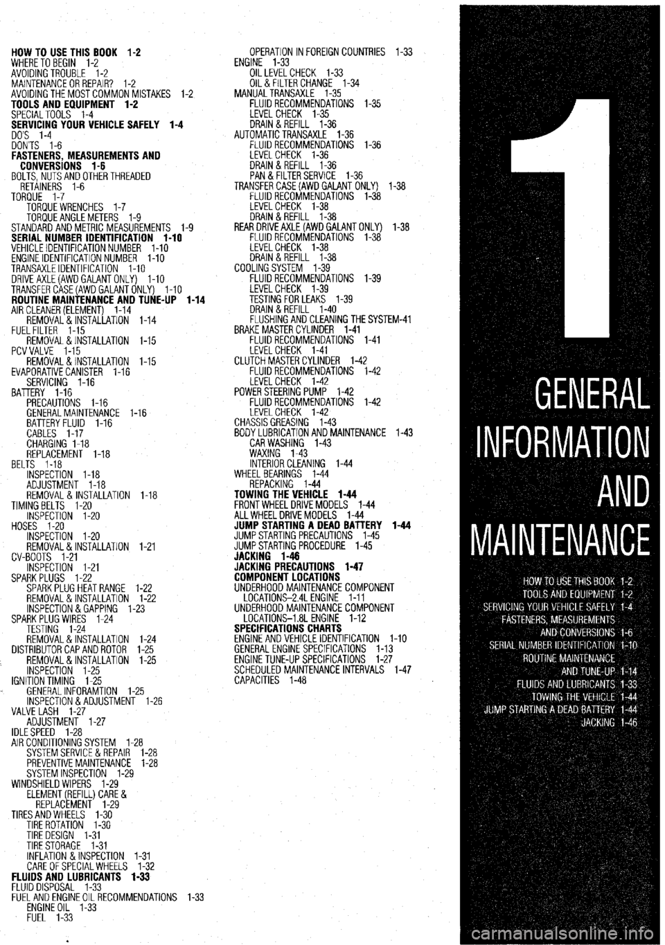
HOW TO USE THIS BOOK 1-2
WHERE TOBEGIN l-2
AVOIDINGTROUBLE 1-2
MAINTENANCEORREPAIR? 1-2
AVOIDINGTHEMOSTCOMMONMISTAKES l-2
TOOLS AND EQUIPMENT 1-2
SPECIALTOOLS l-4
YOUR VEHICLE SAFELY 1-4
DON'TS l-6
FASTENERS, MEASUREMENTS AND
CONVERSIONS l-6
BOLTS,NUTSANDOTHERTHREADED
RETAINERS 1-6
TORQUE l-7
TORQUEWRENCHES l-7
TORQUEANGLEMETERS 1-9
STANDARDANDMETRIC MEASUREMENTS l-9
SERIAL NUMBER IDENTIFICATION l-10
VEHICLE IDENTIFICATION NUMBER l-10
ENGINE IDENTIFICATION NUMBER I-10
TRANSAXLEIDENTIFICATION I-10
DRlVEAXLE(AWDGALANTONLY) l-10
TRANSFERCASE(AWDGALANTONLY) l-10
ROUTINE MAINTENANCE AND TUNE-UP l-14
AIRCLEANER(ELEMENT) 1-14
REMOVAL&INSTALLATION 1-14
FUELFILTER 1-15
REMOVAL &INSTALLATION l-15
PCVVALVE l-15
REMOVAL&INSTALLATION l-15
EVAPORATIVECANISTER l-16
SERVICING 1-16
BATTERY 1-16
PRECAUTIONS I-16
GENERALMAINTENANCE 1-16
BEL BATTERYFLUID 1-16
CABLES I-17
CHARGING I-18
REPLACEMENT 1-18
TS 1-18
INSPECTiON l-18
ADJUSTMENT 1-18
REMOVAL&INSTALLATION 1-18
TIMINGBELTS l-20
INSPECTION l-20
HOSES I-20
INSPECTION l-20
REMOVAL&INSTALLATION
CV-BOOTS 1-21
INSPECTION l-21
SPARKPLUGS l-22
SPARKPLUGHEATRANGE
REMOVAL&INSTALLATION
INSPECTION &GAPPING 1.
SPARKPLUG WIRES 1-24
TESTING 1-24
REMOVAL&INSTALLATION
DISTRIBUTORCAPANDROTOR
REMOVAL&INSTALLATION
INSPECTION 1-25
IGNITIONTIMING 1-25
. GENERALINFORAMTION l-
lNSPECTlON&ADJUSTMENl
VALVE LASH l-27
ADJUSTMENT l-27
IDLESPEED 1-28 1-21
l-22
l-22
-23
1-24
l-25
l-25
.25
1-26
AIR CONDITIONING SYSTEM 1-28
SYSTEMSERVlCEiiREPAlR l-28
PREVENTIVEMAINTENANCE 1-28
SYSTEM INSPECTION l-29
WINDSHIELD WIPERS l-29
ELEMENT(REFILL)CARE&
REPLACEMENT l-29
TIRESANDWHEELS l-30
TIRE ROTATION I-30
TIRE DESIGN 1-31
TIRESTORAGE l-31
INFLATION &INSPECTION l-31
CARE OFSPECIALWHEELS l-32 OPERATION INFOREIGNCOUNTRIES l-33
ENGINE l-33
OILLEVELCHECK 1-33
OIL& FILTER CHANGE l-34
MANUALTRANSAXLE l-35
FLUIDRECOMMENDATIONS l-35
LEVELCHECK l-35
DRAIN&REFILL l-36
AUTOMATICTRANSAXLE l-36
FLUIDRECOMMENDATIONS l-36
LEVELCHECK 1-36
DRAIN&REFILL l-36
PAN & FILTERSERVICE 1-36
TRANSFERCASE(AWDGAlANT ONLY) l-38
FLUIDRECOMMENDATIONS l-38
LEVELCHECK l-38
DRAIN&REFILL l-38
REARDRlVEAXLE(AWDGALANTONLY) l-38
FLUIDRECOMMENDATIONS l-38
LEVELCHECK l-38
DRAIN&REFILL l-38
COOLINGSYSTEM l-39
FLUIDRECOMMENDATIONS l-39
iM-41
FLUIDS AND LUBRICANTS 1-33
FLUID DISPOSAL 1-33
FlJELANDENGlNEOILRECOMMENDATlONS
ENGINE OIL l-33
FUEL l-33
Page 5 of 408
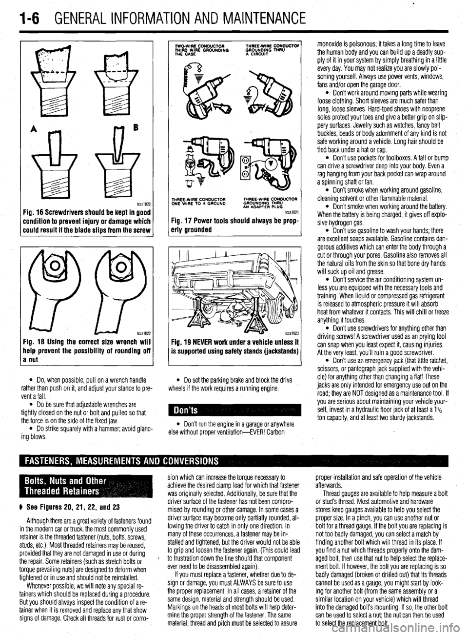
1-6 GENERALINFORMATIONAND MAINTENANCE
Fig. 16 Screwdrivers should be kept in good
:ondition to prevent injury or damage which
:ould result it the blade slips from the screw
0
0
PP tccs1022 Fig. 16 Using the correct size wrench will
help prevent the possibility of rounding off
a nut
7
lwo.WIRE CouDuClOR TMREE-WIRE CONO”CTOI
MIRD WIRE GROUNDING GROUNDING TNRU
THE CASE A CmxlIT
.
i$Y$$pQ
p-+
TNHREE-WIRE CONDUCTOR THREE-WIRE CONDUCTOR
ONE WIRE TO 4 GROUND GROUNOlNG TMRU
AN ADAPTER PLUG
tccm21
Fig. 17 Power tools should always be prop-
erly grounded
Fig. 19 NEVER work under a vehicle unless it
is supported using safety stands (jackstands)
l Do, when possible, pull on a wrench handle l Do set the parking brake and block the drive
rather than push on it, and adjust your stance to pre-
vent a fall. wheels if the work requires a running engine.
l Do be sure that adjustable wrenches are
tightly closed on the nut or bolt and pulled so that
the force is on the side of the fixed jaw.
l Do strike squarely with a hammer; avoid glanc-
ing blows. l Don’t run the engine in a garage or anywhere
else without proper ventilation-EVER! Carbon monoxide is poisonous; it takes a long time to leave
the human body and you can build up a deadly sup-
ply of it in your system by simply breathing in a !ittle
every day. You may not realize you are slowly poi-
soning yourself. Always use power vents, windows,
fans and/or open the garage door.
l Don’t work around moving parts while wearing
loose clothing. Short sleeves are much safer than
long, loose sleeves. Hard-toed shoes with neoprene
soles protect your toes and give a better grip on slip-
pery surfaces. Jewelry such as watches, fancy belt
buckles, beads or body adornment of any kind is not
safe working around a vehicle. Long hair should be
tied back under a hat or cap.
l Don’t use pockets for toolboxes. A fall or bump
can drive a screwdriver deep into your body. Even a
rag hanging from your back pocket can wrap around
a spinning shaft or fan.
l Don’t smoke when working around gasoline,
cleaning solvent or other flammable material.
l Don’t smoke when workrng around the battery.
When the battery is being charged, it gives off explo-
sive hydrogen gas.
l Don’t use gasoline to wash your hands; there
are excellent soaps available. Gasoline contains dan-
gerous additives which can enter the body through a
cut or through your pores. Gasoline also removes all
the natural oils from the skin so that bone dry hands
will suck up oil and grease.
l Don’t service the air conditioning system un-
less you are equipped with the necessary tools and
trainmg. When liquid or compressed gas refrigerant
is released to atmospheric pressure it will absorb
heat from whatever it contacts. This will chill or freeze
anything it touches.
l Don’t use screwdrivers for anything other than
driving screws! A screwdriver used as an prying tool
can snap when you least expect it, causing injuries.
At the very least, you’ll ruin a good screwdriver.
. Don’t use an emergency jack (that little ratchet,
scissors, or pantograph jack supplied with the vehi-
cle) for anything other than changing a flat! These
jacks are only Intended for emergency use out on the
road; they are NOT designed as a maintenance tool. If
you are serious about mamtaining your vehicle your-
self, invest in a hydraulic floor jack of at least a 1%
ton capacity, and at least two sturdy jackstands.
sion which can increase the torque necessary to proper installation and safe operation of the vehicle
achieve the desired clamp load for which that fastener afterwards.
was originally selected. Additionally, be sure that the Thread gauges are available to help measure a bolt
p See Figures 20, 21, 22, and 23 driver surface of the fastener has not been compro- or stud’s thread. Most automotive and hardware
mised by rounding or other damage. In some cases a stores keep gauges available to help you select the
Although there are a great variety of fasteners found driver surface may become only partially rounded, al- proper size. In a pinch, you can use another nut or
in the modern car or truck, the most commonly used lowing the driver to catch in only one direction. In bolt for a thread gauge. If the bolt you are replacing is
retainer is the threaded fastener (nuts, bolts, screws, many of these occurrences, a fastener may be in- not too badly damaged, you can select a match by
studs, etc.). Most threaded retainers may be reused, stalled and tightened, but the driver would not be able finding another bolt which will thread in its place. If
provided that they are not damaged in use or during to grip and loosen the fastener again. (This could lead you find a nut which threads properly onto the dam-
the repair. Some retainers (such as stretch bolts or J to frustration down the line should that component aged bolt, then use that nut to help select the replace-
torque prevailing nuts) are designed to deform when ever need to be disassembled again). ment bolt If however, the bolt you are replacing is so
tightened or in use and should not be reinstalled. If you must replace a fastener, whether due to de- badly damaged (broken or drilled out) that its threads
Whenever possible, we will note any special re- sign or damage, you must ALWAYS be sure to use cannot be used as a gauge, you might start by look-
tainers which should be replaced during a procedure. the proper replacement In all cases, a retainer of the ing for another bolt (from the same assembly or a
But you should always inspect the condition of a re- same design, material and strength should be used. similar location on your vehicle) which will thread
tainer when It is removed and replace any that show Markings on the heads of most bolts will help deter- into the damaged bolt’s mounting. If so, the other bolt
signs of damage. Check all threads for rust or corro- mine the proper strength of the fastener. The same
can be used to select a nut; the nut can then be used
material, thread and pitch must be selected to assure
to select the replacement bolt.
Page 20 of 408
GENERALINFORMATIONAND MAINTENANCE l-21
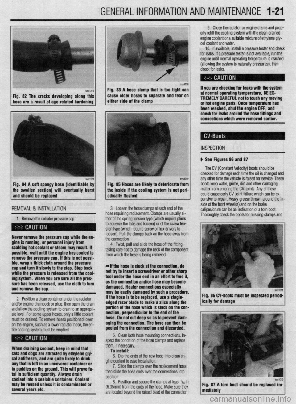
IWSIZXJ FM. 83 A hose clamn that is taa tiaht can
Fig. 82 The cracks developing along this
hose are a result of age-related hardening caise older hoses td separate and ‘iear on
either side of the clamp
lCCS1221 Fig. 84 A soft spongy hose (identifiable by
1 the swollen section) will eventually burst
and should be replaced
IEMOVAL &,INSTALLATION '
1. Remove the radiator pressure cap. her of the sorina tension tvoe (which reouire oliers
3 squeeze the 6bs and loosenj or of the’screw ten-
ion type (which require screw or hex drivers to
oosen). Pull the clamps back on the hose away from
he connection. Never remove the pressure cap while the en-
gine is running, or personal injury from
scalding hot coolant or steam may result. If
possible, wait until the engine has cooled to
remove the pressure cap. If this is not possi-
ble, wrap a thick cloth around the pressure
cap and turn it slowly to the stop. Step back
while the pressure is released from the cool-
ing system. When you are sure all the pres-
sure has been released, use the cloth to turn
and remove the cao.
2. Position a clean container under the radiator
and/or engine draincock or plug, then open the drain
and allow the cooling system to drain to an appropri-
ate level. For some upper hoses, only a little coolant
must be drained. To remove hoses positioned lower
on the engine, such as a lower radiator hose, the en-
tire cooling system must be emptied.
When draining coolant, keep in mind that
cats and dogs are attracted by ethylene gly-
col antifreeze, and are quite likely to drink
any that is left in an uncovered container or
in puddles on the ground. This will prove fa-
tal in sufficient quantity. Always drain
coolant into a sealable container. Coolant
may be reused unless it is contaminated or
several years old. 9. Close the radiator or engine drains and prop-
erly refill the cooling system with the clean drained
engine coolant or a suitable mixture of ethylene gly-
cot coolant and water.
10. If available, install a pressure tester and check
for leaks. If a pressure tester is not available, run the
engine until normal operating temperature is reached
(allowing the system to naturally pressurize), then
check for leaks.
If you are checking for leaks with the system
at normal operating temperature, BE EX-
TREMELY CAREFUL not to touch any moving
or hot engine parts. Once temperature has
been reached. shut the enaine OFF. and
Fig. 85 Hoses are likely to deteriorate from
the inside if the cooling system is not peri-
odically flushed check for leaks around the-hose fittings and
connections which were removed earlier.
INSPECTION
b See Figures 88 and 87
The CV (Constant Velocity) boots should be
checked for damage each time the oil is changed and
any other time the vehicle is raised for service. These
boots keep water, grime, dirt and other damaging
matter from entering the CV-joints. Any of these
could cause early CV-joint failure which can be ex-
pensive to repair. Heavy grease thrown around the in-
side of the front wheel(s) and on the brake
caliper/drum can be an indication of a torn boot.
Thorouahlv check the boots for missina clamos and 3. Loosen the hose clamps at each end of the
rose requiring replacement. Clamps are usually ei-
4. Twist, pull and slide the hose off the fitting,
sking care not to damage the neck of the component
rom which the hose is being removed.
*If the hose is stuck at the connection, do
lot try to insert a screwdriver or other sharp
ool under the hose end in an eff art to free it,
IS the connection and/or hose may become
lamaged. Heater connections especially
nay be easily damaged by such a procedure.
f the hose is to be replaced, use a single-
!dged razor blade to make a slice along the
lortion of the hose which is stuck on the con-
section, perpendicular to the end of the
lose. 00 not cut deep so as to prevent dam-
aging the connection. The hose can then be
keeled from the connection and discarded. Fig. 86 CV-boots must be inspected period-
5.. Clean both hose mounting connections. In-
,pect the condition of the hose clamps and replace
hem, if necessary.
To install:
6. Dip the ends of the new hose into clean en-
fine coolant to ease installation.
7. Slide the clamps over the replacement hose,
hen slide the hose ends over the connections into
rosition.
8. Position and secure the clamps at least l/d in.
6.35mm) from the ends of the hose. Make sure they
Ire located beyond the raised bead of the connector.
Page 21 of 408
l-22 GENERALINFORMATIONAND MAINTENANCE
tears. If the boot is damaged, it should be replaced
trode is to the block’s cooling passages) the cooler it
your driving is long distance, high speed travel, use a
immediately. Please refer to Section 7 for procedures.
will operate. A plug that absorbs little heat and re-
colder plug; if most of your driving is stop and go,
mains too cool will quickly accumulate deposits of
use a hotter plug. Original equipment plugs are gen-
oil and carbon since it is not hot enough to burn
erally a good compromise between the 2 styles and
them off. This leads to plug fouling and consequently
most people never have the need to change their
to misfiring. A plug that absorbs too much heat will
plugs from the factory-recommended heat range.
ti See Figure 88 have no deposits but, due to the excessive heat, the
,electrodes will burn away quickly and might possibly
REMOVAL &INSTALLATION
A typical spark plug consists of a metal shell sur- lead to preignition or other ignition problems. Preig-
rounding a ceramic insulator. A metal electrode ex- nition takes place when plug tips get so hot that they
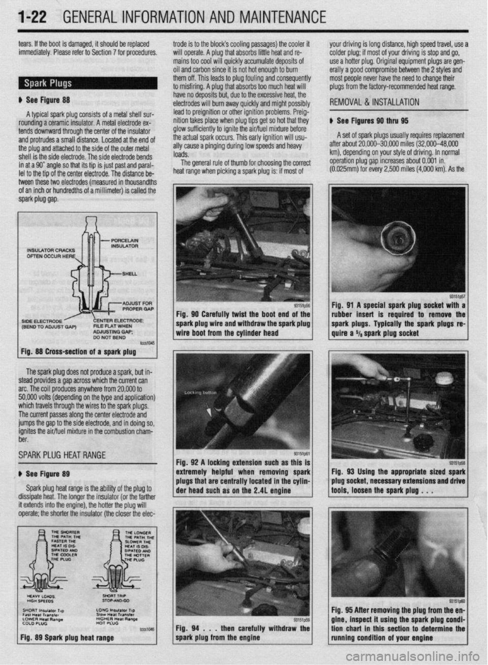
ti See Figures 90 thru 95
tends downward through the center of the insulator glow sufficiently to ignite the air/fuel mixture before
and protrudes a small distance. Located at the end of the actual spark occurs. This early ignition will usu- A set of spark plugs usually requires replacement
the plug and attached to the side of the outer metal ally cause a pinging during low speeds and heavy after about 20,000-30,000 miles (32,000-48,000
shell is the side electrode. The side electrode bends loads. km), depending on your style of driving. In normal
in at a 90” angle so that its tip is just past and paral- The general rule of thumb for choosing the correct operation plug gap increases about 0.001 in.
lel to the tio of the center electrode. The distance be- heat range when picking a spark plug is: if most of (0.025mrn) for every 2,500 miles
(4,000 km). As the
tween these two electrodes (measured in thousandths
of an inch or hundredths of a millimeter) is called the
spark piug gap.
The spark plug does not produce a spark, but in-
steed provides a gap across which the current can
arc. The coil produces anywhere from 20,000 to
50,000 volts (depending on the type and application)
which travels through the wires to the spark plugs.
The current passes along the center electrode and
jumps the gap to the side electrode, and in doing so,
ignites the air/fuel mixture in the combustion charn-
ber.
SPARKPLUG HEATRANGE
ti See Figure 89
Spark plug heat range is the ability of the plug to
dissipate heat. The longer the insulator (or the farther
INSULATOR CRACKS
OFTEN OCCUR HERE
SIDE ELECTRODE ENTER ELECTRODE:
(SEND TO ADJUST GAP) FILE FLAT WHEN
ADJUSTING GAP;
DO NOT BEND
Fig. 88 Cross-section of a spark plug
it extends into the engine), the hotter the plug will
operate; the shorter the insulator (the closer the elec- Fig. 90 Carefully twist the boot end of the
I
spark plug wire and withdraw the spark plug
wire boot from the cylinder head
Fig. 92 A locking extension such as this is
extremely helpful when removing spark
plugs that are centrally located in the cyhn-
Fig. 94 . . .
then carefully withdraw the
spark plug from the engine Fig. 91 A special spark plug socket with a
rubber insert is required to remove the
spark plugs. Typically the spark plugs
re-
quire a Ya spark plug socket
Fig, 93 Using the appropriate sized spark
plug socket, necessary extensions and drive
tools, loosen the spark plug . . .
93151ptxl Fig. 95 After removing the plug from the en-
gine, inspect it using the spark plug condi-
tion chart in this section to determine the
running condition of your engine
Page 27 of 408
l-28 GENERALINFORMATIONAND MAINTENANCE
may result in skin or eye irritation or frostbite. Al- formed to help maintain the efficiency of the vehicle’s
though low in toxicity (due to chemical stability), in- A/C system. For preventive maintenance, perform the
The idle speed is factory set and usually no ad- halation of concentrated refrigerant fumes is danger- following:
justments are ever necessary. If an adjustment be- ous and can result in death; cases of fatal cardiac
l The easiest and most important preventive
comes necessary, first check that the spark plugs, in- arrhythmia have been reported in people accidentally maintenance for your A/C system is to be sure that it
jectors, idle air control servo and compression subjected to high levels of refrigerant. Some early is used on a regular basis. Running the system for
pressure are all normal. symptoms include loss of concentration and drowsi- five minutes each month (no matter what the season)
Data from various sensors and switches are used ness. + will help ensure that the seals and all internal compo-
by the ECU to determine the proper fuel/air mixture
for optimal engine performance. cGeneraiiy, the limit for exposure is lower nents remain lubricated.
for R-134a than it is for R-12. Exceptional *Some newer vehicles automatically oper-
care must be practiced when handling R- ate the A/C system compressor whenever the
134a. windshield defroster is activated. When run-
Also, refrigerants can decompose at high tempera- ning, the compressor lubricates the A/C sys
tures (near gas heaters or open flame), which may re- tern components; therefore, the A/C system
SYSTEM SERVICE& REPAIR suit in hydrofluoric acid, hydrochloric acid and phos- would not need to be operated each month.
gene (a fatal nerve gas). * In order to prevent heater core freeze-up during
R-12 refrigerant can damage the environment be- A/C operation, it is necessary to maintain proper an-
cause it is a Chlorofluorocarbon (CFC), which has tifreeze protection. Use a hand-held coolant tester
been proven to add to ozone layer depletion, leading (hydrometer) to periodically check the condition of
to increasing levels of UV radiation. UV radiation has the antifreeze in your engine’s cooling system.
been linked with an increase in skin cancer, suppres-
sion of the human immune system, an increase in *Antifreeze should not be used longer than
cataracts, damage to crops, damage to aquatic organ- the manufacturer specifies.
isms, an increase in ground-level ozone, and in- . For efficient operation of an air conditioned ve-
creased global warming. hicle’s cooling system, the radiator cap should have a
R-134a refrigerant is a greenhouse gas which, if holding pressure which meets manufacturers specifi-
allowed to vent into the atmosphere, will contribute to cations. A cap which fails to hold these pressures
global warming (the Greenhouse Effect). should be replaced.
It is usually more economically feasible to have a
l Any obstruction of or damage to the condenser
certified MVAC automotive technician perform A/C configuration will restrict air flow which is essential
system service on your vehicle. Some possible rea- to its efficient operation. It is, therefore, a good rule
sons for this are as follows: to keep this unit clean and in proper physical shape.
l While it is illegal to service an A/C system
without the proper equipment, the home mechanic ti See Figure 122
*it is recommended that the A/C svstem be
serviced by an EPA Section 609 cehified au-
tomotivetechnicfan utilizing a refrigerant re-
covery/recycling machfne.
The do-it-yourselfer should not service his/her
own vehicle’s A/C system for many reasons, includ-
ing legal concerns, personal injury, environmental
damage and cost. The following are some of the rea-
sons why you may decide not to service your own ve-
hicle’s A/C system.
According to the U.S. Clean Air Act, it is a federal
crime to service or repair (involving the refrigerant) a
Motor Vehicle Air Conditioning (MVAC) system for
money without being EPA certified. It is also illegal to
vent R-12 and R-134a refrigerants into the atmos-
phere. Selling or distributing A/C system refrigerant
(in a container which contains less than 20 pounds oi
refrigerant) to any person who is not EPA 609 certi-
fied is also not allowed by law.
State and/or local laws may be more strict than the
federal regulations, so be sure to check with your
state and/or local authorities for further information.
For further federal information on the legality of ser-
vicing your AK system, call the EPA Stratospheric
Ozone Hotline.
*Federal law dictates that a fine of up to
$25,000 may be levied on people convicted
of venting refrigerant into the atmosphere.
Additionally, the EPA may pay up to $10,000
for information or services leading to a crimf
nai conviction of the violation of these laws.
When servicing an A/C system you run the risk of
handling or coming in contact with refrigerant, which
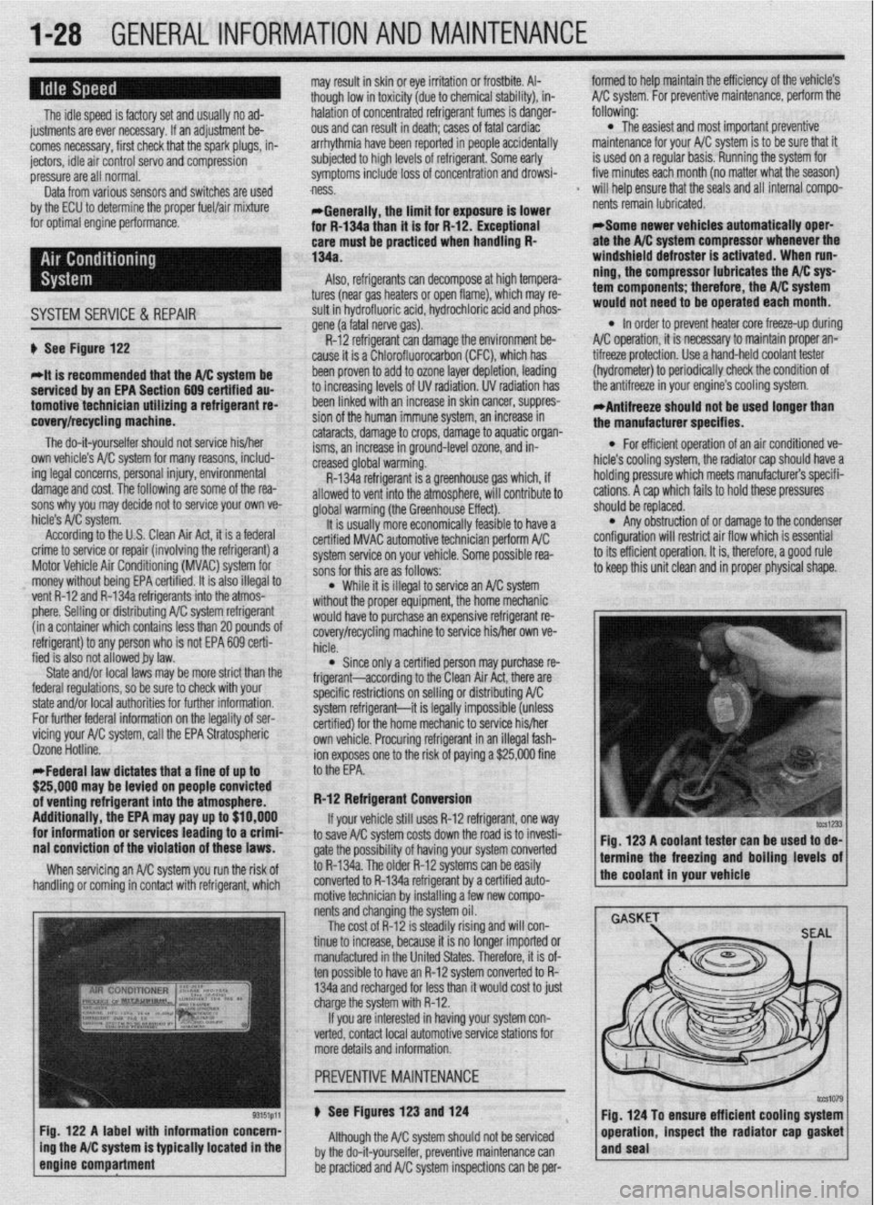
Fig. 122 A label with information concern-
ing the A/C system is typically located in the
engine compartment
f would haveto purchase an expensive refrigerant re-
covery/recycling machine to service his/her own ve-
hicle.
l Since only a certified person may purchase re-
frigerant-according to the Clean Air Act, there are
specific restrictions on selling or distributing A/C
system refrigerant-it is legally impossible (unless
certified) for the home mechanic to service his/her
own vehicle. Procuring refrigerant in an illegal fash-
ion exposes one to the risk of paying a $25,000 fine
to the EPA.
R-12 Refrigerant Conversion
If your vehicle still uses R-12 refrigerant, one
way to save A/C system costs down the road is to invesh-
gate the possibility of having your system converted
to R-134a. The older R-12 systems can be easily
converted to R-134a refrigerant by a certified auto-
motive technician by installing a few new compo-
nents and changing the system oil.
The cost of R-12 is steadily rising and will con-
tinue to increase, because it is no longer imported or
manufactured in the United States. Therefore, it is of-
ten possible to have an R-12 system converted to R-
134a and recharged for less than it would cost to just
charge the system with R-12.
If you are interested in having your system con-
verted, contact local automotive service stations for
more details and information.
u See Figures 123 and 124
Although the A/C system should not be serviced
by the do-it-yourselfer, preventive maintenance can
be practiced and A/C system inspections can be per- Fig. 123 A coolant tester can be used to de-
1 termine the freezing and boiling levels of
the coolant in your vehicle
Fig. 124 To ensure efficient cooling system
operation, inspect the radiator cap gasket
and seal
Page 28 of 408
GENERALINFORMATIONAND MAlNTENANdE 1-29
i
*Bug screens which are mounted in front of
the condenser (unless they are original
equipment) are regarded as obstructtons.
l The condensation drain tube expels any water
which accumulates on the bottom of the evaporator
housing into the engine compartment. If this tube is
obstructed, the air conditioning performance can be
restricted and condensation buildup can spill over
onto the vehicle’s floor.
l Make sure the air passage selection lever is
operating correctly. Start the engine and warm it to
normal operating temperature, then make sure the
temperature selection lever is operating correctly.
-w
~1 ELEMENT(REFILL)CARE& REPLACEMENT
SYSTEM INSPECTION
b See Figure 125 b See Figures 126 thru 135
For maximum effectiveness and longest element
Although the A/C system should not be serviced
by the do-it-yourselfer, preventive maintenance can
be practiced and A/C system inspections can be per-
formed to help maintain the efficiency of the vehicle’s
A/C system. For A/C system inspection, perform the
following:
The easiest and often most important check for the
air conditioning system consists of a visual inspec-
tion of the system components. Visually inspect the
air conditioning system for refrigerant leaks, dam-
aged compressor clutch, abnormal compressor drive
belt tension and/or condition, plugged evaporator
drain tube, blocked condenser fins, disconnected or
broken wires, blown fuses, corroded connections and
poor insulation.
A refrigerant leak will usually appear as an oily
residue at the leakage point in the system. The oily
residue soon picks up dust or dirt particles from the
surrounding air and appears greasy. Through time,
this will build up and appear to be a heavy dirt im-
pregnated grease.
For a thorough visual and operational inspection,
check the following: * Check the surface of the radiator and con-
denser for dirt, leaves or other material which might
block air flow.
l Check for kinks in hoses and lines. Check the
system for leaks.
l Make sure the drive belt is properly tensioned.
When the air conditioning is operating, make sure the
drive belt is free of noise or slippage.
l Make sure the blower motor operates at all ap-
propriate positions, then check for distribution of the
air from all outlets with the blower on HIGH or MAX.
*Keep in mind that under conditions of high
humidity, air discharged from the A/C vents
may not feel as cold as expected, even if the
system is working properly. This is because
vaporized moisture in humid air retains heat
more effectively than dry air, thereby making
humid air more difficult to cool.
lifp thp winrkhi&i nnri winor hlarlP~ shmM hP kmt . ..“. .I.” . . * ““I.. “.” I..” ...r”* “.“““” “, ,““,” “” ,~“r~ clean. Dirt, tree sap, road tar and so on will cause
streaking, smearing and blade deterioration if left on
the glass. It is advisable to wash the windshield care-
fully with a commercial glass cleaner at least once a
month. Wipe off the rubber blades with the wet rag
afterwards. Do not attempt to move wipers across the
windshield by hand; damage to the motor and drive
mechanism will result.
To inspect and/or replace the wiper blade ele-
ments, place the wiper switch in the LOW speed po-
sition and the ignition switch in the ACC position.
When the wiper blades are approximately vertical on
the windshield, turn the ignition switch to OFF.
Examine the wiper blade elements. If they are
found to be cracked, broken or torn, they should be
replaced immediately. Replacement intervals will vary
with usage, although ozone deterioration usually lim-
its element life to about one year. If the wiper pattern
is smeared or streaked, or if the blade chatters across
the glass, the elements should be replaced. It is easi-
est and most sensible to replace the elements in
pairs.
If your vehicle is equipped with aftermarket blades,
there are several different types of refills and your vehi-
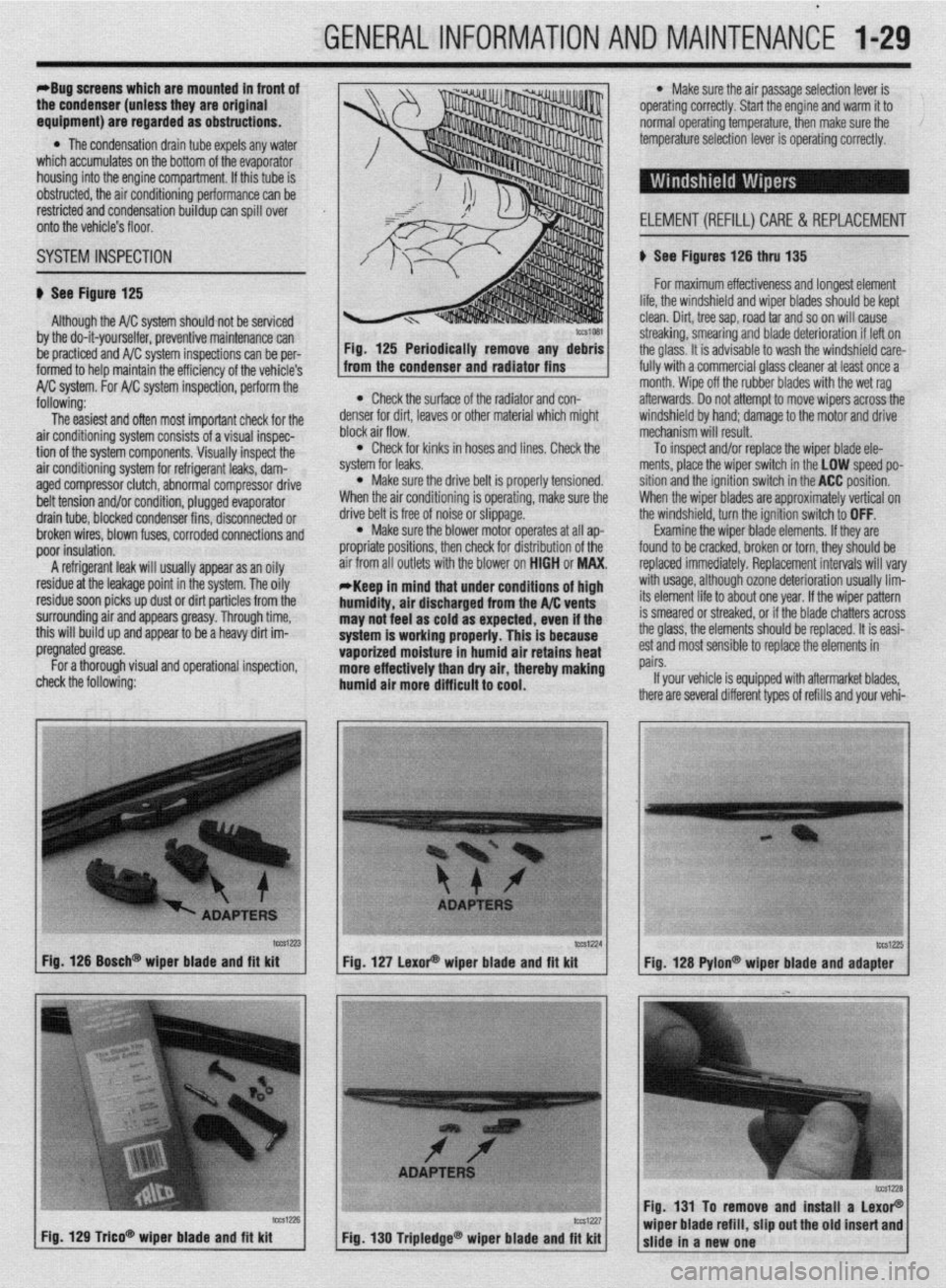
tcca-23 Fig. 126 Bosch@ wiper blade and fft kit
Fig. 129 T&o* wioer blade and fit kit tCS1224
lW1Z?5 Fig. 127 LexoP wiper blade and fit kit
Fig. 128 Pylon@ wiper blade and adapter
Fig. 131 To remove and install a LexoP
Fig, 130 Tripledge@ wiper blade and fit kit wiper blade refill, slip out the old insert and
slide in a new one
Page 31 of 408
.
1-32 GENERALINFORMATIONAND MAINTENANCE
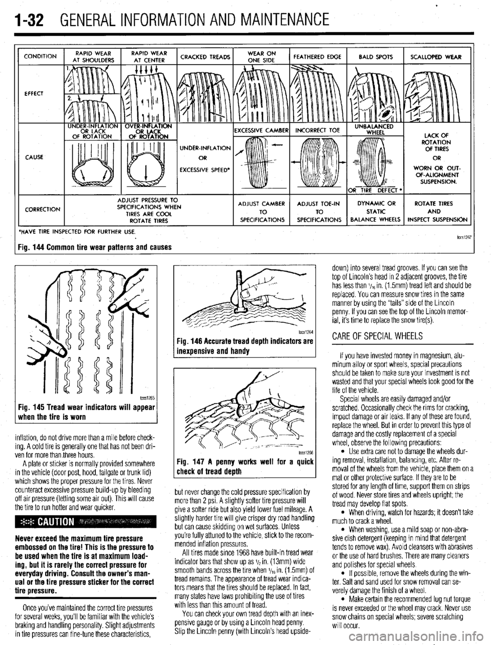
CONDITION
EFFECT
CAUSE
CORRECTION UNDER-INFLATION
EXCESSIVE SPEED’ WORN OR OUT-
OF-ALIGNMENT
ADJUST PRESSURE TO
SPECIFICATIONS WHEN
TIRES ARE COOL
ROTATE TIRES
/ BALANCE WHEELS INSPECT SUSPENSION
HAVE TIRE INSPECTED FOR FURTHER USE.
lCCSi267 ig. 144 Common tire wear patterns and causes
1~~~1265 Fig. 145 Tread wear indicators will appear
when the tire is worn
inflation, do not drive more than a mile before check-
ing. A cold tire is generally one that has not been dri-
ven for more than three hours.
A plate or sticker is normally provided somewhere
in the vehicle (door post, hood, tailgate or trunk lid)
which shows the proper pressure for the tires. Never
counteract excessive pressure build-up by bleeding
off air pressure (letting some air out). This will cause
the tire to run hotter and wear quicker.
Never exceed the maximum tire pressure
embossed on the tire! This is the pressure to
be used when the tire is at maximum load-
ing, but it is rarely the correct pressure for
everyday driving. Consult the owner’s man-
ual or the tire pressure sticker for the correct
tire pressure.
Once you’ve maintained the correct tire pressures
for several weeks, you’ll be familiar with the vehicle’s
braking and handling personality. Slight adjustments
in tire pressures can fine-tune these characteristics,
1~~~1264 Fig. 146 Accurate tread depth indicators are
inexuensive and handv
Fig. 147 A penny works well for a quick
check of tread death
but never change the cold pressure specification by
more than 2 psi. A slightly softer tire pressure will
give a softer ride but also yield lower fuel mileage. A
slightly harder tire will give crisper dry road handling
but can cause skidding on wet surfaces. Unless
you’re fully attuned to the vehicle, stick to the recom-
mended inflation pressures.
All tires made since 1968 have built-in tread wear
indicator bars that show up as j/2 in. (13mm) wide
smooth bands across the bre when V,~ in. (1.5mm) of
tread remains. The appearance of tread wear indica-
tors means that the tires should be replaced. In fact,
many states have laws prohibiting the use of tires
with less than this amount of tread.
You can check your own tread depth with an inex-
pensive gauge or by using a Lincoln head penny.
Shp the Lrncoln penny (with Lincoln’s head upside- down) into several tread grooves. If you can see the
top of Lincoln’s head in 2 adjacent grooves, the tire
has less than V,~ in. (1.5mm) tread left and should be
replaced. You can measure snow tires in the same
manner by using the “tails” side of the Lincoln
penny. If you can see the top of the Lincoln memor-
ial, its time to replace the snow tire(s).
CAREOFSPECIALWHEELS
If you have invested money in magnesium, alu-
minum alloy or sport wheels, special precautions
should be taken to make sure your investment is not
wasted and that your special wheels look good for the
life of the vehicle.
Special wheels are easily damaged and/or
scratched. Occasionally check the rims for cracking,
impact damage or air leaks. If any of these are found,
replace the wheel. But in order to prevent this type of
damage and the costly replacement of a special
wheel, observe the following precautions:
l Use extra care not to damage the wheels dur-
ing removal, installation, balancing, etc. After re-
moval of the wheels from the vehicle, place them on a
mat or other protective surface. If they are to be
stored for any length of time, support them on strips
of wood. Never store tires and wheels upright; the
tread may develop flat spots.
l When driving, watch for hazards; it doesn’t take
much to crack a wheel.
l When washing, use a mild soap or non-abra-
sive dish detergent (keeping in mind that detergent
tends to remove wax). Avoid cleansers with abrasives
or the use of hard brushes. There are many cleaners
and polishes for special wheels.
l If possrble, remove the wheels during the win-
ter. Salt and sand used for snow removal can se-
verely damage the finish of a wheel.
l Make certain the recommended lug nut torque
is never exceeded or the wheel may crack. Never use
snow chains on special wheels; severe scratching
will occur.
Page 35 of 408
.
l-36 GENERALINFORMATIONAND MAINTENANCE
Install the drain plug and tighten to 22 ft. Ibs.
(304Nm)
5. Refill the transaxle to the proper level, as
shown in the Capacities chart, with the appropriate
fluid. The oil level should be at the bottom of the oil
filler hole. I
6. When the oil reaches the orooer level, install
the filler plug and tighten to 22 ft. Ibs. (30 Nm).
FLUID RECOMMENDATIONS
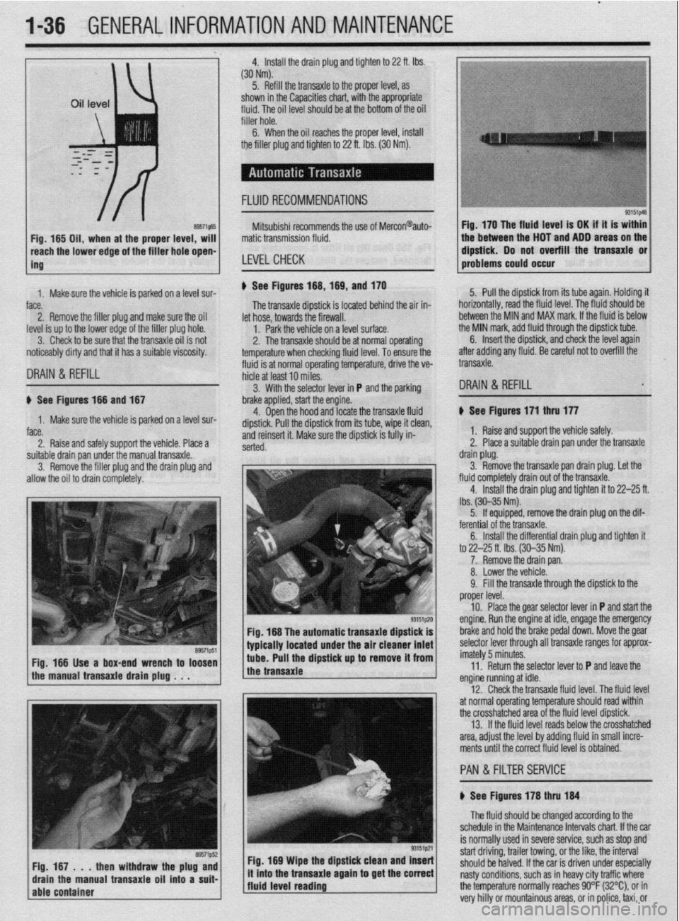
8957i565 Fig, 165 Oil, when at the proper level, will
reach the lower edge of tC=+ frfr*r u*rn -non-
ing Mitsubishi recommends the use of Mercon@auto-
matic transmission fluid.
LEVELCHECK
Fig. 170 The fluid level is OK if it is within
the between the HOT and ADD areas on the
&&i& Do not overfill the transaxle or
-.*".."... -- .*"- problems could o ccur
1. Makesure the vehicle is oarked on a level sur-
face.
2. Remove the filler plug and make sure the oil
level is up to the lower edge of the filler plug hole.
3. Check to be sure that the transaxle oil is not
noticeably dirty and that it has a suitable viscosity. u See Figures 168,169, and 170
fluid is at normal operating temperature, drive the ve- The transaxle dipstick is located behind the air in-
hicle at least 10 miles. let hose, towards the firewall.
1. Park the vehicle on a level surface.
2. The transaxle should be at normal operating
temperature when checking fluid level. To ensure the 5. Pull the dipstick from its tube again. Holding it
horizontally, road the fluid level. The fkrid should be
between the MIN and MAX mark. If the fluid is below
the MIN mark, add fluid through the dipstick tube.
DRAIN & REFILL
6. Insert the dipstick, and check the level again
after adding any fluid. Be careful not to overfill the
transaxle.
3. With the selector lever in P and the parking
DRAIN & REFILL u See Figures 166 and 167
1. Make sure the vehicle is parked on a level sur-
face.
2. Raise and safely support the vehicle. Place a brake applied, start the engine.
4. Open the hood and locate the transaxle fluid
dipstick. Pull the dipstick from its tube, wipe it clean,
and reinsert it. Make sure the dipstick is fully in-
serted.
suitable drain pan under the manual transaxle.
3. Remove the filler plug and the drain plug and
allow the oil to drain completely.
Fig. 166 The automatic transaxle dipstick is
typically located under the air cleaner inlet
Fig. 166 Use a box-end wrench to loosen
the manual transaxle drain plug . . . tube. Pull the dipstick up to remove it from
the transaxle
Fig. 169 Wipe the dipstick clean and Insert
/fluid level reading ., it mto the transaxle agam to get the correct
j The fluid should be changed according to the
schedule in the Maintenance Intervals chart. If the car
is normally used in severe service, such as stop and
start driving, trailer towing, or the like, the interval
should be halved. If the car is driven under especially
nasty conditions, such as in heavy city traffic where
the temperature normally reaches 90°F (32%), or in
very hilly or mountainous areas, or in police, taxi, or b See Figures 171 thru 177
1. Raise and support the vehicle safely.
2. Place a suitable drain pan under the transaxle
drain plug.
3. Remove the transaxle pan drain plug. Let the
fluid completely drain out of the transaxle.
4. Install the drain plug and tighten it to 22-25 ft.
lbs. (30-35 Nm).
5. If equipped, remove the drain plug on the dif-
ferential of the transaxle.
6. Install the differential drain plug and tighten ft
to 22-25 ft. Ibs. (30-35 Nm).
7. Remove the drain pan.
8. Lower the vehicle.
9. Fill the transaxle through the dipstick to the
proper level.
10. Place the gear selector lever in P and start the
engine. Run the engine at idle, engage the emergency
brake and hold the brake pedal down. Move the gear
selector lever through all transaxle ranges for approx-
imately 5 minutes.
11. Return the selector lever to P and leave the
engine running at idle.
12. Check the transaxle fluid level. The fluid level
at normal operating temperature should read within
the crosshatched area of the fluid level dipstick.
13. If the fluid level reads below the crosshatched
area, adjust the level by adding fluid in small incre-
ments until the correct fluid level is obtained.
PAN &FILTER SERVICE
b See Figures 178 thru 184
Page 40 of 408
.
GENERALINFORMATIONAND MAINTENANCE l-41
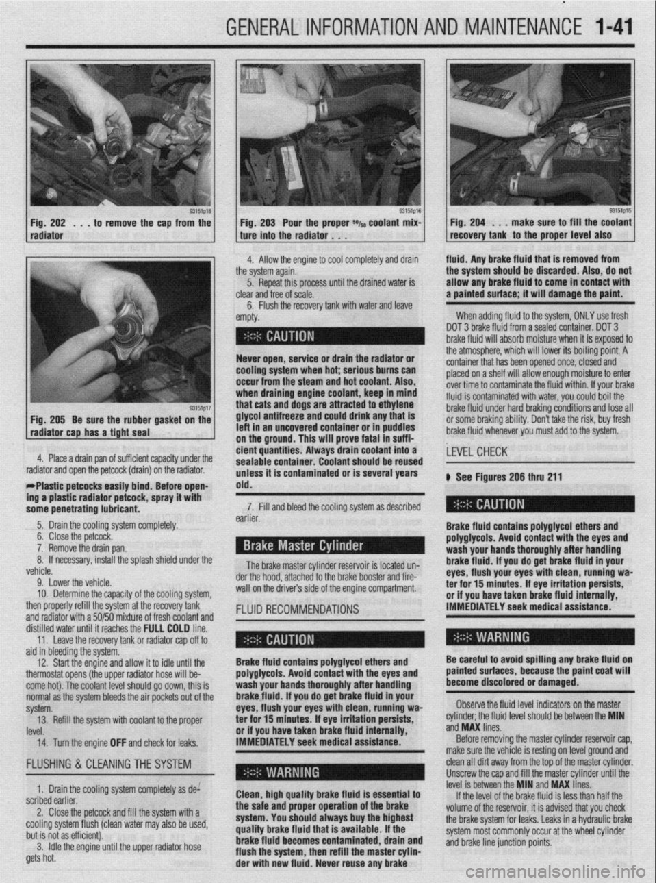
93151p18 Fig. 202 . , . to remove the cap from the
radiator
93151p17 Fig. 205 Be sure the rubber gasket on the
radiator cap has a tight seal e Fig. 203 Pour the proper *I~ coolant mix- 1 Fig. 204 . . . make sure to fill the coolant
recovery tank to the proper level also ture into the radiator . . .
.I
4. Allow the engine to cool completely and drain fluid. Any brake fluid that is removed from
ie system again.
5. Repeat this processuntil the drained water is
lear
and free of scale.
6. Flush the recovery tank with water and leave ’
mpty. the system should be discarded. Also, do not
allow any brake fluid to come in contact with
a painted surface; it will damage the paint.
When adding fluid to the system, ONLY use fresh
DOT 3 brake fluid from a sealed container. DOT 3
brake fluid will absorb moisture when it is exposed to
.a . . . , .*a. . . * .*. . .
- Never open, service or drain the radiator or
cooling system when hot; serious bums can
occur from the steam and hot coolant. Also,
when draining engine coolant, keep In mind
that cats and dogs are attracted to ethylene
glycol antifreeze and could drink any that is
left in an uncovered container or in puddles
on the ground. This will prove fatal in suffi-
4. Place a drain pan of suff i ’ 1 . . . ..I .I. 1,~ cient quantities. Always tne atmospnere, wnrcn wnr rower 1r.s oourng pomr. A
container that has been opened once, closed and
placed on a shelf will allow enough moisture to enter
over time to contaminate the fluid within. If your brake
fluid is contaminated with water, you could boil the
brake fluid under hard braking conditions and lose all
or some braking ability. Don’t take the risk, buy fresh
brake fluid whenever you must add to the system.
crenr capacrry unaer me
drain) on the radiator.
rrrasuc perwcss easuy bind; Before open-
ing a plastic radiator petcock, spray it with
some penetrating lubricant. drain coolant into a
earner. sealable container. Coolant should be reused
unless it is contaminated or is several years
old.
The brake master cylinder ~a~~~~r,~~ :A I~nnL.4 n-n 7. Fill and bleed the cooling system as described
Brake fluid contains polyglycol ethers and
polyglycols. Avoid contact with the eyes and ,LEVEL CHECK
wash your hands thoroughly after handling
brake fluid. If vou do oet brake fluid in vour
eyes, flush your eyeswith clean, runniug wa-
a-.. ‘Y-- ar -l-..n-- II -.._ I____ k See Figures 206 thru 211
.a-11-- - __-PA._ radiator and open the petcock (
- w&1--x3_ --mm.._..- . . ..-I...
5. Drain the cooling system completely.
6. Close the petcock.
7. Remove the drain pan.
If necessary, install the splash shield under the 8.
L.-l
venicie.
9. Lower the vehicle.
10. Determine the capacity of the cooling system,
then properly refill the system at the recovery tank
and radiator with a 50/50 mixture of fresh coolant and
fKm”“ll 15 IUMLC” “II- brake booster and fire- der the hood, attached to the
wall on the drivers side of the engine compartment.
FLUID RECOMMENDATIONS rer mr 13 mmures. IT eye irriIauon persim, or if you have taken brake fluid internally,
IMMEDIATELY seek medical assistance.
ala in oreerring me sysrem.
12. Start the engine and allow it to idle until the
thermostat opens (the upper radiator hose will be-
come hot). The coolant level should go down, this is
normal as the system bleeds the air pockets out of the
svstem.
IRVf!l ._._. 14. Turn the engine OFF and check for leaks. IMMEDIATELY seek medical assistance.” Brake fluid contains polyglycol ethers and
polyglycols. Avoid contact with the eyes and
wash your hands thoroughly after handling
brakefluid. If you do get brake fluid in your
eyes, flush your eyes with clean, running wa-
or if vou have taken brake fluid internallv.
Before removing the master cylinder reservoir cap,
make sure the vehicle is resting on level ground and Be careful to avoid spilling any brake fluid on
painted surfaces, because the paint coat will
become discolored or damaged.
Observe the fluid level indicators on the master
._ ._ __
‘eve1 should be between the MIN
ano
ivw unes. 13. Refill the system with coolant to the proper ter for 15 minutes; If eye irritation persists, cylinder; the tluld II
..J ..I” I....
FLUSHING & CLEANINGTHE SYSTEM
1. Drain the cooling system completely as de:
scribed earlier.
2. Close the petcock and fill the system with a
cooling system flush (clean water may also be used,
but is not as efficient).
3. Idle the engine until the upper radiator hose
gets hot. Clean, high quality brake fluid is essential to
the safe and proper operation of the brake
system. You should always buy the highest
quality brake fluid that is available. If the
brake fluid becomes contaminated, drain and
flush the system, then refill the master cylin-
der with new fluid. Never reuse any brake clean all dirt away from the top of the master cylinder.
Unscrew the cap and fill the master cylinder until the
level is between the MIN and MAX lines.
If the level of the brake fluid is less than half the
volume of the reservoir, it is advised that you check
the brake system for leaks. Leaks in a hydraulic brake
system most commonly occur at the wheel cylinder
and brake line junction points.
Page 46 of 408
GENERAL INFORMATION AND MAINTENANCE 1-47
ramps are also a handy and safe way to both raise l When the drive wheels are to remain on the
and support the vehicle. Be careful though, some ground, leave the vehicle in gear to help prevent it
ramps may be too steep to drive your vehicle onto
The following safety points cannot be overempha- from rolling.
without scraping the front bottom panels. Never sup-
sized:
l Always use jackstands to support the vehicle
port the vehicle on any suspension member (unless l Always block the opposite wheel or wheels to when you are working underneath. Place the stands
specifically instructed to do so by a repair manual) or
keep the vehicle from rolling off the jack. beneath the vehrcle’s jacking brackets Before climb-
by an underbody panel.
l When raising the front of the vehicle, firmly ap- ing underneath, rock the vehicle a bit to make sure it
ply the parking brake. is firmly supported.
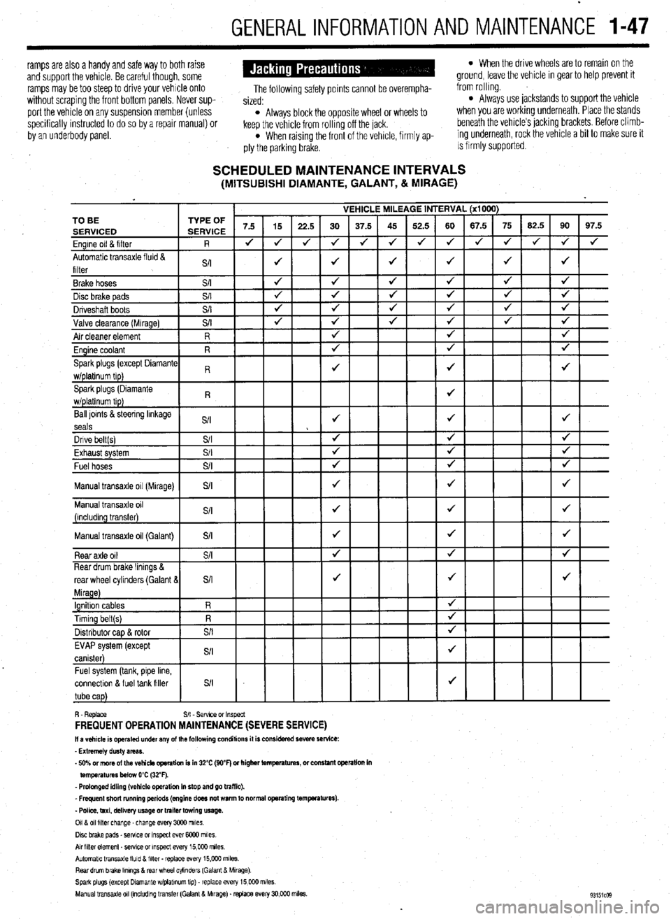
SCHEDULED MAINTENANCE INTERVALS (MITSUBISHI DIAMANTE, GALANT, & MIRAGE)
VEHICLE MILEAGE INTERVAL (x1000)
7.5 15
22.5 30 37.5 45 52.5 60 67.5 75 62.5 90 97.5
J J
J 4 J J 4 4 4 J J
J 4
4
J J J J 4 TO BE
Ball loints &steering linkage
S/I J J J
seals
Dnve belt(s) S/I 4 4 J
Fvha,,rt cvctom $/I
J J J LmI,..“w. “,YL”,‘. Fuel hoses
+
Manual transaxle oil (Galant)
connectlon & fuel tank filler
R. Replace S/I - Sefwce or Inspect FREQUENT OPERATION MAINTENANCE (SEVERE SERVICE) II a vehicle is operated under any of the following conditions it is considered severe service:
- Extremely dusty areas.
- 50% or more of the vehicle operation is in 32% (WF) or higher temperatures, or constant opsralion in
temperatures below 0% (32°F).
- Prolonged idling (vehicle operation in stop and go traffic).
_ Frequent short running periods (engine does not warm to normal operating temfwatures).
- Police, taxi, delivery usage or trailer towing usage.
0118 011 filter change-change every 3CQO miles.
Disc brake pads - sewce or Inspect ever 6COO miles
AN hlter element _ setwe or inspect every 15,000 miles.
Automatic transaxle lluld 8 filter . replace every 15,COO m&s.
Rear drum brake Ikmngs & rear wheel cylinders (Galant & Mirage)
Spark plugs (except Dlamante wlplabnum tip) - replace every 15,COO miles.
Manual transaxle 011 (mcludlng transfer (Galant & Mirage). replace every 30,000 miles.