compression ratio MITSUBISHI DIAMANTE 1900 Repair Manual
[x] Cancel search | Manufacturer: MITSUBISHI, Model Year: 1900, Model line: DIAMANTE, Model: MITSUBISHI DIAMANTE 1900Pages: 408, PDF Size: 71.03 MB
Page 26 of 408
GENERALINFORMATIONAND MAlNTENANdE I-27
ADJUSTMENT
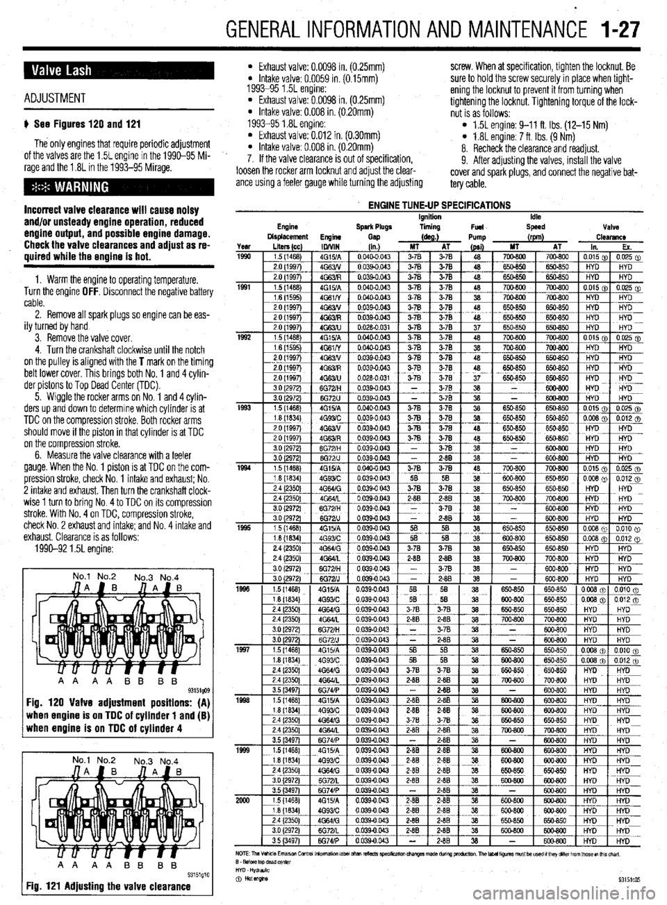
u See Figures 120 and 121
The only engines that require periodic adjustment
of the valves are the 1.5L engine in the 1990-95 Mi-
rage and the 1.8L in the 1993-95 Mirage.
Incorrect valve clearance will cause noisy
and/or unsteady engine operation, reduced
engine output, and possible engine damage.
Check the valve clearances and adjust as re-
quired while the engine is hot.
1. Warm the engine to operating temperature.
Turn the engine OFF. Disconnect the negative battery
cable.
2. Remove all spark plugs so engine can be eas-
ily turned by hand
3. Remove the valve cover.
4. Turn the crankshaft clockwise until the notch
on the pulley is aligned with the
T mark on the timing
belt lower cover. This brings both No. 1 and 4 cylin-
der pistons to Top Dead Center (TDC).
5. Wiggle the rocker arms on No. 1 and 4 cylin-
ders up and down to determine which cylinder is at
TDC on the compression stroke. Both rocker arms
should move if the piston in that cylinder is at TDC
on the compression stroke.
6. Measure the valve clearance with a feeler
gauge. When the No. 1 piston is at TDC on the com-
pression stroke, check No. 1 intake and
exhaust; No.
2 intake and exhaust. Then turn the crankshaft clock-
wise 1 turn to bring No. 4 to TDC on its compression
stroke. With No. 4 on TDC, compression stroke,
check No. 2 exhaust and intake; and No. 4 intake and
exhaust. Clearance is as follows:
1990-92 1.5L engine:
No.1 No.2
No.3 No.4
when engine is on TDC of cylinder 1 and (B) when engine is on TDC of cylinder 4
No.1 No.2
No.3 No.4
AA AA BB BB
93151g10 Fig. 121 Adjusting the valve clearance
l Exhaust valve: 0.0098 in. (0.25mm) screw. When at specification, tighten the locknut. Be l Intake valve: 0.0059 in. (0.15mm)
1993-95 1.5L engine: sure to hold the screw securely in place when tight-
l Exhaust valve: 0.0098 in. (0.25mm) ening the locknut to prevent it from turning when
* Intake valve: 0.008 in. (0.20mm) tightening the locknut. Tightening torque of the lock-
nut is as follows:
1993-95 1.8L engine:
l Exhaust valve: 0.012 in. (0.30mm) l 1.5L engine: 9-11 ft. Ibs. (12-15 Nm)
l Intake valve: 0.008 in. (0.20mm) l 1.8L engine: 7 ft. Ibs. (9 Nm)
8. Recheck the clearance and readjust.
7. If the valve clearance is out of specification,
9. After adjusting the valves, install the valve
loosen the rocker arm locknut and adjust the clear-
ante using a feeler gauge while turning the adjusting cover and spark plugs, and connect the negative bat-
tery cable.
Engine
ENGINE TUNE-UP SPECIFICATIONS Ignition
Spark Plugs liming
Fuel Idle
Speed Valve
Displacement
Engine
Gap (as.) Pump (rpm)
Clearance
Page 27 of 408
l-28 GENERALINFORMATIONAND MAINTENANCE
may result in skin or eye irritation or frostbite. Al- formed to help maintain the efficiency of the vehicle’s
though low in toxicity (due to chemical stability), in- A/C system. For preventive maintenance, perform the
The idle speed is factory set and usually no ad- halation of concentrated refrigerant fumes is danger- following:
justments are ever necessary. If an adjustment be- ous and can result in death; cases of fatal cardiac
l The easiest and most important preventive
comes necessary, first check that the spark plugs, in- arrhythmia have been reported in people accidentally maintenance for your A/C system is to be sure that it
jectors, idle air control servo and compression subjected to high levels of refrigerant. Some early is used on a regular basis. Running the system for
pressure are all normal. symptoms include loss of concentration and drowsi- five minutes each month (no matter what the season)
Data from various sensors and switches are used ness. + will help ensure that the seals and all internal compo-
by the ECU to determine the proper fuel/air mixture
for optimal engine performance. cGeneraiiy, the limit for exposure is lower nents remain lubricated.
for R-134a than it is for R-12. Exceptional *Some newer vehicles automatically oper-
care must be practiced when handling R- ate the A/C system compressor whenever the
134a. windshield defroster is activated. When run-
Also, refrigerants can decompose at high tempera- ning, the compressor lubricates the A/C sys
tures (near gas heaters or open flame), which may re- tern components; therefore, the A/C system
SYSTEM SERVICE& REPAIR suit in hydrofluoric acid, hydrochloric acid and phos- would not need to be operated each month.
gene (a fatal nerve gas). * In order to prevent heater core freeze-up during
R-12 refrigerant can damage the environment be- A/C operation, it is necessary to maintain proper an-
cause it is a Chlorofluorocarbon (CFC), which has tifreeze protection. Use a hand-held coolant tester
been proven to add to ozone layer depletion, leading (hydrometer) to periodically check the condition of
to increasing levels of UV radiation. UV radiation has the antifreeze in your engine’s cooling system.
been linked with an increase in skin cancer, suppres-
sion of the human immune system, an increase in *Antifreeze should not be used longer than
cataracts, damage to crops, damage to aquatic organ- the manufacturer specifies.
isms, an increase in ground-level ozone, and in- . For efficient operation of an air conditioned ve-
creased global warming. hicle’s cooling system, the radiator cap should have a
R-134a refrigerant is a greenhouse gas which, if holding pressure which meets manufacturers specifi-
allowed to vent into the atmosphere, will contribute to cations. A cap which fails to hold these pressures
global warming (the Greenhouse Effect). should be replaced.
It is usually more economically feasible to have a
l Any obstruction of or damage to the condenser
certified MVAC automotive technician perform A/C configuration will restrict air flow which is essential
system service on your vehicle. Some possible rea- to its efficient operation. It is, therefore, a good rule
sons for this are as follows: to keep this unit clean and in proper physical shape.
l While it is illegal to service an A/C system
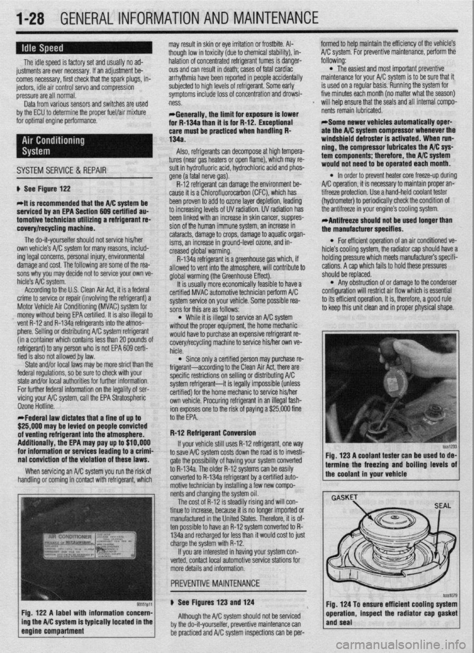
without the proper equipment, the home mechanic ti See Figure 122
*it is recommended that the A/C svstem be
serviced by an EPA Section 609 cehified au-
tomotivetechnicfan utilizing a refrigerant re-
covery/recycling machfne.
The do-it-yourselfer should not service his/her
own vehicle’s A/C system for many reasons, includ-
ing legal concerns, personal injury, environmental
damage and cost. The following are some of the rea-
sons why you may decide not to service your own ve-
hicle’s A/C system.
According to the U.S. Clean Air Act, it is a federal
crime to service or repair (involving the refrigerant) a
Motor Vehicle Air Conditioning (MVAC) system for
money without being EPA certified. It is also illegal to
vent R-12 and R-134a refrigerants into the atmos-
phere. Selling or distributing A/C system refrigerant
(in a container which contains less than 20 pounds oi
refrigerant) to any person who is not EPA 609 certi-
fied is also not allowed by law.
State and/or local laws may be more strict than the
federal regulations, so be sure to check with your
state and/or local authorities for further information.
For further federal information on the legality of ser-
vicing your AK system, call the EPA Stratospheric
Ozone Hotline.
*Federal law dictates that a fine of up to
$25,000 may be levied on people convicted
of venting refrigerant into the atmosphere.
Additionally, the EPA may pay up to $10,000
for information or services leading to a crimf
nai conviction of the violation of these laws.
When servicing an A/C system you run the risk of
handling or coming in contact with refrigerant, which
Fig. 122 A label with information concern-
ing the A/C system is typically located in the
engine compartment
f would haveto purchase an expensive refrigerant re-
covery/recycling machine to service his/her own ve-
hicle.
l Since only a certified person may purchase re-
frigerant-according to the Clean Air Act, there are
specific restrictions on selling or distributing A/C
system refrigerant-it is legally impossible (unless
certified) for the home mechanic to service his/her
own vehicle. Procuring refrigerant in an illegal fash-
ion exposes one to the risk of paying a $25,000 fine
to the EPA.
R-12 Refrigerant Conversion
If your vehicle still uses R-12 refrigerant, one
way to save A/C system costs down the road is to invesh-
gate the possibility of having your system converted
to R-134a. The older R-12 systems can be easily
converted to R-134a refrigerant by a certified auto-
motive technician by installing a few new compo-
nents and changing the system oil.
The cost of R-12 is steadily rising and will con-
tinue to increase, because it is no longer imported or
manufactured in the United States. Therefore, it is of-
ten possible to have an R-12 system converted to R-
134a and recharged for less than it would cost to just
charge the system with R-12.
If you are interested in having your system con-
verted, contact local automotive service stations for
more details and information.
u See Figures 123 and 124
Although the A/C system should not be serviced
by the do-it-yourselfer, preventive maintenance can
be practiced and A/C system inspections can be per- Fig. 123 A coolant tester can be used to de-
1 termine the freezing and boiling levels of
the coolant in your vehicle
Fig. 124 To ensure efficient cooling system
operation, inspect the radiator cap gasket
and seal
Page 51 of 408
2-4 ENGINEELECTRICAL
2. Install the distributor in the engine so the rotor
is aligned with the matchmark on the housing and the
housing is aligned with the matchmark on the engine.
4.‘ Remove the retaining screws and coil from en-
gine.
5. Installation is the reverse of the removal proce-
dure. Before removing the distributor, position No. 1
‘cylinder at Top Dead Center (TDC) on the compres-
sion stroke and align the timing marks.
1. Disconnect the negative battery cable.
2. Remove the ignition wire cover, if equipped.
3. Detach the distributor harness connector.
4. Remove the distributor cap with all ignition wires
still connected. Remove the coil wire, if necessary.
5. Matchmark the rotor to the distributor housing
and the distributor housing to the engine.
6. Remove the hold-down nut.
7. Carefully remove the distributor from the engine.
INSTALLATION
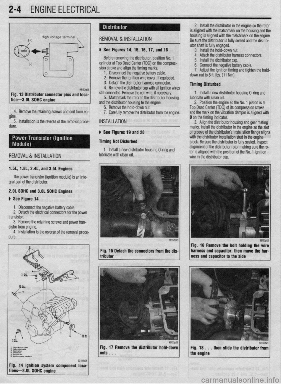
6 See Figures 19 and 2g
Timing Not Disturbed
1, Install a new distributor housing O-ring and 4. Attach the distributor harness connectors.
5. Install the distributor cap.
6. Connect the negative battery cable.
7. Adjust the ignition timing and tighten the hold-
down nut to 6 ft. Ibs. (11 Nm).
Timing Dlsturbed
1. Install a new distributor housing O-ring and
lubricate with clean oil.
2. Position the engine so the No. 1 piston is at
Top Dead Center (TDC) of its compression stroke
and the mark on the vibration damper is aligned with
REMOVALS& INSTALLATION lubricate with clean oil. 0 on the timing indicator.
3. Align the distributor housing and gear mating
marks. Install the distributor in the engine so the slot
or groove of the distributor’s installation flange aligns
with the distributor installation stud in the engine
block. Be sure the distributor is fully seated. Inspect
alignment of the distributor rotor making sure the ro- tnr ic dinnnd with thn qn,c$nn of the Nn innitinn
ISL, 1 AIL, 2.4L, and 3.5L Engines
The power transistor (ignition module) is an inte-
gral part of the distributor.
2.gL SDHC and 3.OL SOHC Engines
# See Figure 14
1 x Disconnect the negative battery cable.
Remove the retaining screws and power tran-
Detach the connectors from the dis- Fig. 16 Remove the bolt holding the wire
harness and capacitor, then move the har-
ness and capacitor to the side
Fig. 18 . . . then slide the distributor from
the engine
/ tion’s-3.gL SOHC engine g3is~@ 1 Fig 14 Ignition system component loca-
Page 62 of 408
ENGINE MECHANICAL 3-1
ENGINE 3-1
REMOVAL &INSTALLATION 3-l
ROCKERARM(VALVE)COVER 3-l
REMOVAL &INSTALLATION 3-l
ROCKER ARM/SHAFTS 3-4
REMOVAL & INSTALLATION 3-4
THERMOSTAT 3-7
REMOVAL & INSTALLATION 3-7
INTAKE MANIFOLD 3-7
REMOVAL & INSTALLATION 3-7
EXHAUSTMANIFOLD 3-14
REMOVAL &INSTALLATION 3-14
TURBOCHARGER 3-17
REMOVAL & INSTALLATION 3-17
RADIATOR 3-18
REMOVAL & INSTALLATION 3-18
ENGINE FAN 3-19
REMOVAL &INSTALLATION 3-19
WATER PUMP 3-20
REMOVAL & INSTALLATION 3-20
CYLINDER HEAD 3-23
REMOVAL &INSTALLATION 3-23
OIL PAN 3-30
REMOVAL & INSTALLATION 3-30
OIL PUMP 3-33
REMOVAL &INSTALLATION 3-33
CRANKSHAFT DAMPER 3-36
REMOVAL &INSTALLATION 3-36
TIMING COVERAND BELT 3-36
REMOVAL & INSTALLATION 3-36
INSPECTION 3-48
FRONT CRANKSHAFTSEAL 3-48
REMOVAL & INSTALLATION 3-48
CAMSHAFT,BEARlNGSAND
LIFTERS 3-48
REMOVAL & INSTALLATION 3-48
INSPECTION 3-53
BALANCE SHAFT 3-54
REMOVAL &INSTALLATION 3-54
REAR MAIN SEAL 3-54
REMOVAL&INSTALLATION 3-54
FLYWHEEL/DRIVEPLATE 3-55
REMOVAL &INSTALLATION 3-55
EXHAUST SYSTEM 3-55
INSPECTION 3-55
REPLACEMENT 3-56
ENGINE RECONDITIONING 3-57
DETERMINIG ENGINE CONDITION 3-57
COMPRESSION TEST 3-57
OIL PRESSURETEST 3-57
BUYOR REBUILD? 3-57
ENGINE OVERHAULTIPS 3-58
TOOLS 3-58
OVERHAULTIPS 3-58
CLEANING 3-58
REPAIRING DAMAGEDTHREADS 3-59
ENGINE PREPARATION 3-59
CYLINDER HEAD 3-60
DISASSEMBLY 3-60
INSPECTION 3-
REFINISHING & REPAIRING 3-63 ASSEMBLY 3-64
ENGINE BLOCK 3-65
GENERALINFORMAITON 3-65
DISASSEMBLY 3-65
INSPECTION 3-65
REFINISHING 3-67
ASSEMBLY 3-67
ENGINE START-UP AND BREAK-IN 3-
STARTING THE ENGINE 3-69
BREAKING IT IN 3-69
KEEP IT MAINTAINED 3-69
SPECIFICATIONS CHARTS
ENGINE MECHANICAL
SPECIFICATIONS 3-70
TORQUE SPECIFICATIONS 3-81 .69
Page 99 of 408
3-38 ENGINEANDENGINEOVERHAUL
1.61&? 2.OL (Non-Turbo) DOHC Engines
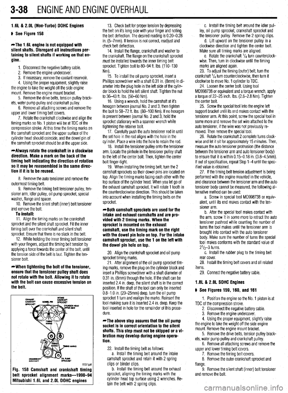
g See Figure 158
*The 1.6L engine is not equipped with
silent shafts. Disregard all instructions per-
taining to silent shafts if working on that en-
gine.
1. Disconnect the negative battery cable.
2. Remove the engine undercover.
3. If necessary, remove the coolant reservoir.
4. Using the proper equipment, slightly raise
the engine to take the weight off the side engine
mount. Remove the engine mount bracket.
5. Remove the drive belts, tension pulley brack-
ets, water pump pulley and crankshaft pulley.
6. Remove all attaching screws and remove the
upper and lower timing belt covers.
7. Rotate the crankshaft clockwise and align the
timing marks so No. 1 piston will be at TDC of the
compression stroke. At this time the timing marks on
the camshaft sprocket and the upper surface of the
cylinder head should coincide, and the dowel pin of
the camshaft sprocket should be at the upper side.
*Always rotate the crankshaft in a clockwise
direction. Make a mark on the back of the
timing belt indicating the direction of rotation
so it may be reassembled in the same direc-
tion if it is to be reused.
8. Remove the auto tensioner and remove the
outermost timing belt.
9. Remove the timing belt tensioner pulley, ten-
sioner arm, idler pulley, oil pump sprocket, special
washer, flange and spacer.
10. Remove the silent shaft (inner) belt tensioner
and remove the belt.
To install: 11. Align the timing marks on the crankshaft
sprocket and the silent shaft sprocket. Fit the inner
timing belt over the crankshaft and silent shaft
sprocket. Ensure that there is no slack in the belt.
12. While holding the inner timing belt tensioner
with your fingers, adjust the timing belt tension by
applying a force towards the center of the belt, until
the tension side of the belt is taut. Tighten the ten-
sioner bolt.
*When tightening the bolt of the tensioner,
ensure that the tensioner pulley shaft does
not rotate with the bolt. Allowing it to rotate
with the bolt can cause excessive tension on
the belt.
13. Check belt for proper tension by depressing
the belt on it’s long side with your finger and noting
the belt deflection. The desired reading is 0.20-0.28
in. (5-7mm). If tension is not correct, readjust and
check belt deflection.
14. Install the flange, crankshaft and washer to
the crankshaft. The flange on the crankshaft sprocket
must be installed towards the inner trming belt
sprocket. Tighten bolt to 80-94 ft. Ibs. (110-130
Nm).
15. To install the oil pump sprocket, insert a
Phillips screwdriver with a shaft 0.31 in. (8mm) in di-
ameter into the plug hole in the left side of the cylin-
der block to hold the left silent shaft. Tighten the nut
to 36-43 ft. Ibs. (50-60 Nm).
16. Using a wrench, hold the camshaft at it’s
hexagon between journal No. 2 and 3, then tighten
the bolt to 58-72 ft. Ibs. (80-100 Nm). If no hexagon
is present between journal No. 2 and 3, hold the
sprocket stationary with a spanner wrench while
tightening the retainer bolt.
17. Carefully push the auto tensioner rod in until
the set hole in the rod aligns with the hole in the
cylinder. Place a wire into the hole to retain the rod.
18. Install the tensioner pulley onto the tensioner
arm. Locate the pinhole in the tensioner pulley shaft
to the left of the center bolt. Then, tighten the center
bolt finger-tight.
19. When installing the timing belt, turn the 2
camshaft sprockets so their dowel pins are located on
top. Align the timing marks facing each other with the
top surface of the cylinder head. When you let go of
the exhaust camshaft sprocket, it will rotate 1 tooth in
the counterclockwise direction. This should be taken
into account when installing the timing belts on the
sprocket.
*Both camshaft sprockets are used for the
intake and exhaust camshafts and are pro-
vided with 2 timing marks. When the
sprocket is mounted on the exhaust
camshaft, use the timing mark on the right
with the dowel pin hole on top. For the intake
camshafl sprocket, use the 1 on the left with
the dowel pin hole on top.
20. Align the crankshaft sprocket and oil pump
sprocket timing marks.
21. After alignment of the oil pump sprocket tim-
ing marks, remove the plug on the cylinder block and
insert a Phillips screwdriver with a shaft diameter of
0.31 in. (8mm) through the hole. If the shaft can be
inserted 2.4 in. deep, the silent shaft is in the correct
position. If the shaft of the tool can only be inserted
0.61 .O in. (2C-25mm) deep, turn the oil pump
sprocket 1 turn and realign the marks. Reinsert the
tool making sure it is inserted 2.4 in. deep. Keep the
tool inserted in hole for the remainder of this proce-
dure.
*The above step assures that the oil pump
socket is in correct orientation to the silent
shafts. This step must not be skipped or a vi-
bration may develop during engine opera-
tion.
22. Install the timing belt as follows:
a. Install the timing belt around the intake
camshaft sprocket and retain it with 2 spring
clips or binder clips.
b. Install the timing belt around the exhaust
sprocket, aligning the timing marks with the
cylinder head top surface using 2 wrenches. Re-
tain the belt with 2 spring clips. c. Install the timing belt around the idler pul-
ley, oil pump sprocket, crankshaft sprocket and
the tensioner pulley. Remove the 2 spring clips.
d. Lift upward on the tensioner pulley in a
clockwise direction and tighten the center bolt.
Make sure all timing marks are aligned.
e. Rotate the crankshaft ‘14 turn counterclock-
wise. Then, turn in clockwise until the timing
marks are alrgned again.
23. To adjust the timing (outer) belt, turn the
crankshaft ‘14 turn counterclockwise, then turn it
clockwise to move No. 1 cylinder to TDC.
24. Loosen the center bolt. Using tool
MD998738 or equivalent and a torque wrench, apply
a torque of 22-25 inch. Ibs. (2.6-2.8 Nm). Tighten
the center bolt.
25. Screw the special tool into the engine left
support bracket until its end makes contact with the
tensioner arm. At this point, screw the special tool in
some more and remove the set wire attached to the
auto tensioner, if the wire was not previously re-
moved. Then remove the specral tool.
26. Rotate the crankshaft 2 complete turns clock-
wise and let it sit for approximately 15 minutes. Then,
measure the auto tensioner protrusion (the distance
between the tensioner arm and auto tensioner body)
to ensure that it is within 0.15-0.18 in. (3.8-4.5mm).
If out of specification, repeat Step l-4 until the spec-
ified value is obtained.
27. If the timing belt tension adjustment is being
performed with the engine mounted in the vehicle,
and clearance between the tensioner arm and the auto
tensioner body cannot be measured, the following al-
ternative method can be used:
a. Screw in special tool MD998738 or equiv-
alent, until its end makes contact with the ten-
sioner arm.
b. After the special tool makes contact with
the arm, screw it in some more to retract the auto
tensioner pushrod while counting the number of
turns the tool makes until the tensioner arm is
brought into contact with the auto tensioner
body. Make sure the number of turns the special
tool makes conforms with the standard value of
21/a-3 turns.
c. Install the rubber plug to the timing belt
rear cover.
28. Install the timing belt covers and all related
items.
29. Connect the negative battery cable.
1.8L & 2.OL SOHC Engines
g See Figures 159, 160, and 161
1. Position the engine so the No. 1 piston is at
TDC of the compression stroke.
2. Disconnect the negative battery cable.
3. Remove the engine undercover.
4. Using the proper equipment, slightly raise
the engine to take the weight off the side engine
mount. Remove the engine mount bracket.
5. Remove the drive belts, tension pulley brack-
ets, water pump pulley and crankshaft pulley.
6. Remove all attaching screws and remove the
upper and lower timing belt covers.
7. Remove the timing belt covers.
8. Remove the outer crankshaft sprocket and
flange.
9. Remove the silent shaft (inner) belt tensioner
and remove the belt.
Page 103 of 408
.
3-42 ENGINEANDENGINEOVERHAUL
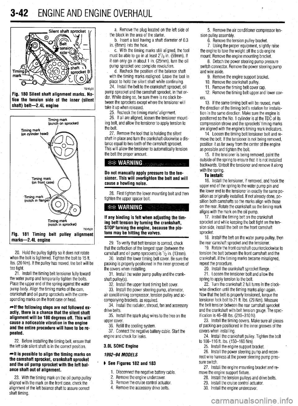
Fig. 180 Silent shaft alignment marks. No,
tice the tension side of the inner (silen
shaft) belt-2.41 enaine
Timing merk
(pun+ on sprocket)
liming m&k
(notch in sprocket)
79245g31 :ig. 181 Timing belt pulley alignmenl
narks-2.41 enoine
20. Hold the pulley tightly so it does not rotate
when the bolt is tlghtened. Tighten the bolt to 15 ft.
Ibs. (20 Nm). If the pulley has moved, the belt will be
too tight
21. Install the timing belt tensioner fully toward
the water pump and temporarily tighten the bolts.
Place the upper end of the spring against the water
pump body. Align the timing marks of the cam,
crankshaft and oil pump sprockets with the corre-
sponding marks on the front case or head.
*If the following steps are not followed ex-
actly, there is a chance that the silent shaft
alignment will be 180 degrees off. This will
cause a noticeable vibration in the engine
and the entire procedure will have to be re-
peated.
22. Before installing the timing belt, ensure that
the left side silent shaft is in the correct position.
*It is possible to align the timing marks on
the camshaft sprocket, crankshaft sprocket
and the oil pump sprocket with the lefl bal-
ance shaft out of alignment.
23. With the timing mark on the oil pump pulley
aligned with the mark on the front case, check the
alignment of the left balance shaft to assure correct
shaft timing. a. Remove the plug located on the left side of
the block in the area of the starter.
b. Insert a tool having a shaft diameter of 0.3
in. (8mm) into the hole.
c. With the timing marks still aligned, the tool
must be able to go in at least 2l/s in. (59mm). If
it can only go m about 1 in. (25mm), turn the oil
pump sprocket one complete revolution.
d. Recheck the position of the balance shaft
with the timing marks reahgned. Leave the tool in
place to hold the silent shaft while continuing.
24. Install the belt to the crankshaft sprocket, oil
pump sprocket and the camshaft sprocket, in that or-
der. While doing so, be sure there is no slack be-
tween the sprockets except where the tensioner will
take it up when released.
25. Recheck the timing marks’ alignment.
26. If all are aligned, loosen the tensioner mount-
ing bolt, and allow the tensioner to apply tension to
the belt.
27. Remove the tool that is holding the silent
shaft in place and turn the crankshaft clockwise a dis-
tance equal to two teeth of the camshaft sprocket.
This will allow the tensioner to automatically tension
the belt the proper amount.
Do not manually apply pressure to the ten-
sioner. This will overtighten the belt and will
cause a howling noise.
28. First tighten the lower mounting bolt and then
tighten the upper spacer bolt.
If any binding is felt when adiustino the tim-
ing delt tension by turning th;! crankshaft,
STOP turning the engine, because the pis-
tons may be hitting the valves.
29. To verify that belt tension is correct, check
that the deflection of the longest span (between the
camshaft and oil pump sprockets) is I/* in. (13mm).
30. Install the lower timing belt cover. Be sure the
packing is properly positioned in the inner grooves of
the covers when installing.
31. Install the water pump pulley and the crank-
shaft pulley(s).
32. Install the upper front timing belt cover.
33. Install the power steering pump, alternator,
air conditioning compressor, tension pulley and ac-
companying brackets, as required.
34. Install the radiator, shroud, fan and accessory
drive belts.
35. Install the spark plug wires to the tree on the
upper cover.
36. Refill the cooling system.
37. Connect the negative battery cable. Start the
engme and check for leaks.
3.OL SDHC Engine
1992-94 MODELS
# See Figures 182 and 183
1. Disconnect the negative battery cable.
2. Remove the engine undercover
3. Remove the cruise control
actuator 4. Remove the accessory drive belts. 5. Remove the air conditioner compressor ten-
sion pulley assembly.
6. Remove the tension pulley bracket.
7. Using the proper equipment, slightly raise
the engine to take the weight off the side engine
mount. Remove the engine mounting bracket.
8. Detach the power steering pump pressure
switch connector. Remove the power steering pump
and wire aside.
9. Remove the engine support bracket.
10. Remove the crankshaft pulley.
11. Remove the timing belt cover cap.
12. Remove the timing belt upper and lower cov-
ers.
13. If the same timing belt will be reused, mark
the direction of the timing belt’s rotation for installa-
tion in the same direction. Make sure the engine is
positioned so the No. 1 cylinder is at the TDC of its
compression stroke and the sprockets’ timing marks
are aligned with the engine’s timing mark indicators.
14. Loosen the timing belt tensioner bolt and re-
move the belt. If the tensioner is not being removed,
position it as far away from the center of the engine
as possible and tighten the bolt.
15. If the tensioner is being removed, paint the
outside of the spring to ensure that it is not installed
backwards. Unbolt the tensioner and remove it along
with the spring.
To install:
16. Install the tensioner, if removed, and hook the
upper end of the spring to the water pump pin and
the lower end to the tensioner in exactly the same po-
sition as originally installed. If not already done, po-
sition both camshafts so the marks align with those
on the rear. Rotate the crankshaft so the timing mark
aligns with the mark on the oil pump.
17. Install the timing belt on the crankshaft
sprocket and while keeping the belt tight on the ten-
sion side, install the belt on the front camshaft
sprocket.
18. Install the belt on the water pump pulley, then
the rear camshaft sprocket and the tensioner.
19. Rotate the front camshaft counterclockwise to
tension the belt between the front camshaft and the
crankshaft. If the tlmlng marks became misaligned,
repeat the procedure.
20. Install the crankshaft sprocket flange.
21. Loosen the tensioner bolt and allow the
spring to apply tension to the belt.
22. Turn the crankshaft 2 full turns in the clock-
wise direction until the timing marks align again.
Now that the belt is properly tensioned, torque the
tensioner lock bolt to 21 ft. Ibs. (29 Nm). Measure
the belt tension between the rear camshaft sprocket
and the crankshaft with belt tension gauge, The spec-
ification is 46-68 Ibs. (210-310 N).
23. Install the timing covers. Make sure all pieces
of packing are positioned in the inner grooves of the
covers when Installing.
24. install the crankshaft pulley. Tighten the bolt
to 108-116ft. Ibs. (150-160 Nm)
25. Install the engine support bracket.
26. Install the power steering pump and recon-
nect wire harness at the power steering pump pres-
sure switch.
27. Install the engine mounting bracket and re-
move the engine support fixture.
28. Install the tension pulleys and drive belts.
29. Install the cruise control actuator.
30 Install the engine undercover.
Page 388 of 408
II-6 TROUBLESHOOTING
DIAGhUSTIC PROCEDURES
Gasoline Engines
1. Engine turns over, but wilt not start
a. Check fuel level in fuel tank, add fuel if empty.
b. Check battery condition and state of charge. If voltage and load test below specifica-
tion, charge or replace battery.
c. Check battery terminal and cable condition and tightness. Clean terminals and replace
damaged, worn or corroded cables.
d. Check fuel delivery system. If fuel is not reaching the fuel injectors, check for a loose
electrical connector or defective fuse, relay or fuel pump and replace as necessary.
e. Engine may have excessive wear or mechanical damage such as low cylinder cranking
pressure, a broken camshaft drive system, insufficient valve clearance or bent valves.
f. Check for fuel contamination such as water in the fuel. During winter months, the wa-
ter may freeze and cause a fuel restriction. Adding a fuel additive may help, however
the fuel system may require draining and purging with fresh fuel.
g. Check for ignition system failure. Check for loose or shorted wires or damaged igni-
tion system components. Check the spark plugs for excessive wear or incorrect elec-
trode gap. If the problem is worse in wet weather, check for shorts between the spark
plugs and the ignition coils.
h. Check the engine management system for a failed sensor or control module.
2. Engine does not turn over when attempting to start
a. Check the battery state of charge and condition. If the dash lights are not visible or
very dim when turning the ignition key on, the battery has either failed internally or
discharged, the battery cables are loose, excessively corroded or damaged, or the al-
ternator has failed or internally shorted, discharging the battery. Charge or replacethe
battery, clean or replace the battery cables, and check the alternator output.
b. Check the operation of the neutral safety switch. On automatic transmission vehicles,
try starting the vehicle in both Park and Neutral. On manual transmission vehicles, de-
press the clutch pedal and attempt to start. On some vehicles, these switches can be
adjusted. Make sure the switches or wire connectors are not loose or damaged. Re-
place or adjust the switches as necessary.
c. Check the starter motor, starter solenoid or relay, and starter motor cables and wires.
Check the ground from the engine to the chassis. Make sure the wires are not loose,
damaged, or corroded. If battery voltage is present at the starter relay, try using a re-
mote starter to start the vehicle for test purposes only. Replace any damaged or cor-
roded cables, in addition to replacing any failed components.
d. Check the engine for seizure. If the engine has not been started for a long period of
time, internal parts such as the rings may have rusted to the cylinder walls. The engine
may have suffered internal damage, or could be hydro-locked from ingesting water.
Remove the spark plugs and carefully attempt to rotate the engine using a suitable
breaker bar and socket on the crankshaft pulley. If the engine is resistant to moving, or
moves slightly and then binds, do not force the engine any further before determining
the problem.
3. Enpine stalls immediately when started
a. Check the ignition switch condition and operation. The electrical contacts in the run
position may be worn or damaged. Try restarting the engine with all electrical acces-
sories in the off position. Sometimes turning the key on an off will help in emergency
situations, however once the switch has shown signs of failure, it should be replaced
as soon as possible.
b. Check for loose, corroded, damaged or shorted wires for the ignition system and re-
pair or replace.
c. Check for manifold vacuum leaks or vacuum hose leakage and repair or replace parts
as necessary.
d. Measure the fuel pump delivery volume and pressure. Low fuel pump pressure can
also be noticed as a lack of power when accelerating. Make sure the fuel pump lines
are not restricted. The fuel pump output is not adjustable and requires fuel pump re-
placement to repair.
e. Check the engine fuel and ignition management system. Inspect the sensor wiring and
electrical connectors. A dirty, loose or damaged sensor or control module wire can
simulate a failed component.
f. Check the exhaust system for internal restrictions.
4. Starter motor spins, but does not engage
a. Check the starter motor for a seized or binding pinion gear.
b. Remove the flywheel inspection plate and check for a damaged ring gear.
5. Engine is difficult to start when Gold
a. Check the battery condition, battery state of charge and starter motor current draw. Re-
place the battery if marginal and the starter motor if the current draw is beyond specifi-
cation. b. Check the battery cable condition. Clean the battery terminals and replace corroded or
damaged cables.
c. Check the fuel system for proper operation. A fuel pump with insufficient fuel pressure
or clogged injectors should be replaced.
d. Check the engine’s tune-up status. Note the tune-up specifications and check for items
such as severely worn spark plugs; adjust or replace as needed. On vehicles with
manually adjusted valve clearances, check for tight valves and adjust to specification.
e. Check for a failed coolant temperature sensor, and replace if out of specification.
f. Check the operation of the engine management systems for fuel and ignition; repair or
replace failed components as necessary.
6. En#ine is ditticutt to start when hot
a. Check the air filter and air intake system. Replace the air filter if it is dirty or contami-
nated. Check the fresh air intake system for restrictions or blockage.
b. Check for loose or deteriorated engine grounds and clean, tighten or replace as
needed.
c. Check for needed maintenance. Inspect tune-up and service related items such as
spark plugs and engine oil condition, and check the operation of the engine fuel and
ignition management system.
Diesel Engines
1. Engine turns over but won’t start
a. Check engine starting procedure and restart engine.
b. Check the glow plug operation and repair or replace as necessary.
c. Check for air in the fuel system or fuel filter and bleed the air as necessary.
d. Check the fuel delivery system and repair or replace as necessary.
e. Check fuel level and add fuel as needed.
f. Check fuel quality. If the fuel is contaminated, drain and flush the fuel tank.
g. Check engine compression. If compression is below specification, the engine may
need to be renewed or replaced.
h. Check the injection pump timing and set to specification.
i. Check the injection pump condition and replace as necessary.
j. Check the fuel nozzle operation and condition or replace as necessary.
2. Engine does
hot turn over when attempting to start
a. Check the battery state of charge and condition. If the dash lights are not visible or
very dim when turning the ignition key on, the battery has either failed internally or
discharged, the battery cables are loose, excessively corroded or damaged, or the al-
ternator has failed or internally shorted, discharging the battery. Charge or replace the
battery, clean or replace the battery cables, and check the alternator output.
b. Check the operation of the neutral safety switch. On automatic transmission vehicles,
try starting the vehicle in both Park and Neutral. On manual transmission vehicles, de-
press the clutch pedal and attempt to start. On some vehicles, these switches can be
adjusted. Make sure the switches or wire connectors are not loose or damaged. Re-
place or adjust the switches as necessary.
c. Check the starter motor, starter solenoid or relay, and starter motor cables and wires.
Check the ground from the engine to the chassis. Make sure the wires are not loose,
damaged, or corroded. If battery voltage is present at the starter relay, try using a re-
mote starter to start the vehicle for test purposes only. Replace any damaged or cor-
roded cables, in addition to replacing any failed components.
d. Check the engine for seizure. If the engine has not been started for a long period of
time, internal parts such as the rings may have rusted to the cylinder walls. The engine
may have suffered internal damage, or could be hydro-locked from ingesting water.
Remove the injectors and carefully attempt to rotate the engine using a suitable
breaker bar and socket on the crankshaft pulley. If the engine is resistant to moving, or
moves slightly and then binds, do not force the engine any further before determining
the cause of the problem.
3. Engine stalls afier starting
a. Check for a restriction in the fuel return line or the return line check valve and repair as
necessary.
b. Check the glow plug operation for turning the glow plugs off too soon and repair as
necessary.
c. Check for incorrect injection pump timing and reset to specification.
d. Test the engine fuel pump and replace if the output is below specification.
e. Check for contaminated or incorrect fuel. Completely flush the fuel system and replace
with fresh fuel.
f. Test the engine’s compression for low compression. If below specification, mechanical
repairs are necessary to repair.
g. Check for air in the fuel. Check fuel tank fuel and fill as needed.
h. Check for a failed injection pump. Replace the pump, making sure to properly set the
pump timing.
Page 389 of 408
TROUBLESHOOiNG 11-7
4. Starter motor spins, but does not engage
a. Check the starter motor for a seized or binding pinion gear.
b. Remove the flywheel inspection plate and check for a damaged ring gear.
Gasoline Engines
1. Engine runs poor/y, hesiiates
a. Check the engine ignition system operation and adjust if possible, or replace defective
parts.
b. Check for restricted fuel injectors and replace as necessary.
c. Check the fuel pump output and delivery. Inspect fuel lines for restrictions. If the fuel
pump pressure is below specification, replace the fuel pump.
d. Check the operation of the engine management system and repair as necessary.
2. Enfline lacks power
a. Check the engine’s tune-up status. Note the tune-up specifications and check for items
such as severely worn spark plugs; adjust or replace as needed. On vehicles with
manually adjusted valve clearances, check for tight valves and adjust to specification.
b. Check the air filter and air intake system. Replace the air filter if it is dirty or contami-
nated. Check the fresh air intake system for restrictions or blockage.
c. Check the operation of the engine fuel and ignition management systems. Check the
sensor operation and wiring. Check for low fuel pump pressure and repair or replace
components as necessary.
d. Check the throttle linkage adjustments. Check to make sure the linkage is fully open-
ing the throttle. Replace any worn or defective bushings or linkages.
e. Check for a restricted exhaust system. Check for bent or crimped exhaust pipes, or in-
ternally restricted mufflers or catalytic converters. Compare inlet and outlet tempera-
tures for the converter or muffler. If the inlet is hot, but outlet cold, the component is
restricted.
f. Check for a loose or defective knock sensor. A loose, improperly torqued or defective
knock sensor will decrease spark advance and reduce power. Replace defective knock
sensors and install using the recommended torque specification.
g. Check for engine mechanical conditions such as low compression, worn piston rings,
worn valves, worn camshafts and related parts. An engine which has severe mechani-
cal wear, or has suffered internal mechanical damage must be rebuilt or replaced to re-
store lost power.
h. Check the engine oil level for being overfilled. Adjust the engine’s oil level, or change
the engine oil and filter, and top off to the correct level.
i. Check for an intake manifold or vacuum hose leak. Replace leaking gaskets or worn
vacuum hoses.
j. Check for dragging brakes and replace or repair as necessary.
k. Check tire air pressure and tire wear. Adjust the pressure to the recommended set-
tings. Check the tire wear for possible alignment problems causing increased rolling
resistance, decreased acceleration and increased fuel usage.
I. Check the octane rating of the fuel used during refilling, and use a higher octane rated
fuel.
3. Poor fuel economy
a. Inspect the air filter and check for any air restrictions going into the air filter housing.
Replace the air filter if it is dirty or contaminated.
b. Check the engine for tune-up and related adjustments. Replace worn ignition parts,
check the engine ignition timing and fuel mixture, and set to specifications if possible.
c. Check the tire size, tire wear, alignment and tire pressure. Large tires create more
rolling resistance, smaller tires require more engine speed to maintain a vehicle’s road
speed. Excessive tire wear can be caused by incorrect tire pressure, incorrect wheel
alignment or a suspension problem. All of these conditions create increased rolling
resistance, causing the engine to work harder to accelerate and maintain a vehicle’s
speed.
d. Inspect the brakes for binding or excessive drag. A sticking brake caliper, overly ad-
justed brake shoe, broken brake shoe return spring, or binding parking brake cable or
linkage can create a significant drag, brake wear and loss of fuel economy. Check the
brake system operation and repair as necessary.
4. Engine runs on (diesels) when turned off
a. Check for idle speed set too high and readjust to specification.
b. Check the operation of the idle control valve, and replace if defective.
c. Check the ignition timing and adjust to recommended settings.
Check for defective
sensors or related components and replace if defective.
d. Check for a vacuum leak at the intake manifold or vacuum hose
and replace defective
gaskets or hoses.
e. Check the engine for excessive carbon build-up in the combustion chamber. Use a
recommended decarbonizing fuel additive or disassemble the cylinder head to remove
the carbon.
f. Check the operation of the engine fuel management system and replace defective sen-
sors or control units.
g. Check the engine operating temperature for overheating and repair as necessary. 5. Engine knocks and pinfls during heavy accele/ation, and on steep hills
a. Check the octane rating of the fuel used during refilling, and use a higher octane rated
fuel.
b. Check the ignition timing and adjust to recommended settings. Check for defective
sensors or related components and replace if defective.
c. Check the engine for excessive carbon build-up in the combustion chamber. Use a
recommended decarbonizing fuel additive or disassemble the cylinder head to remove
the carbon.
d. Check the spark plugs for the correct type, electrode gap and heat range. Replace worn
or damaged spark plugs. For severe or continuous high speed use, install a spark plug
that is one heat range colder.
e. Check the operation of the engine fuel management system and replace defective sen-
sors or control units.
f. Check for a restricted exhaust system. Check for bent or crimped exhaust pipes, or in-
ternally restricted mufflers or catalytic converters. Compare inlet and outlet tempera-
tures for the converter or muffler. If the inlet is hot, but outlet cold, the component is
restricted.
6. Engine atxelerates, but vehicle does not gain speed
a. On manual transmission vehicles, check for causes of a slipping clutch. Refer to the
clutch troubleshooting section for additional information.
b. On automatic transmission vehicles, check for a slipping transmission” Check the
transmission fluid level and condition. If the fluid level is too high, adjust to the cor-
rect level. If the fluid level is low, top off using the recommended fluid type. If the fluid
exhibits a burning odor, the transmission has been slipping internally. Changing the
fluid and filter may help temporarily, however in this situation a transmission may re-
quire overhauling to ensure long-term reliability.
Diesel Engines
1. Engine runs pOOr!y a. Check the injection pump timing and adjust to specification.
b. Check for air in the fuel lines or leaks, and bleed the air from the fuel system.
c. Check the fuel filter, fuel feed and return lines for a restriction and repair as necessary.
d. Check the fuel for contamination, drain and flush the fuel tank and replenish with fresh
fuel.
2. Enfline lacks power
a. Inspect the air intake system and air filter for restrictions and, if necessary, replace the
air filter.
b. Verify the injection pump timing and reset if out of specification.
c. Check the exhaust for an internal restriction and replace failed parts.
d. Check for a restricted fuel filter and, if restricted, replace the filter.
e. Inspect the fuel filler cap vent. When removing the filler cap, listen for excessive hiss-
ing noises indicating a blockage in the fuel filler cap vents, If the filler cap vents are
blocked, replace the cap.
f. Check the fuel system for restrictions and repair as necessary.
g. Check for low engine compression and inspect for external leakage at the glow plugs
or nozzles. If no external leakage is noted, repair or replace the engine.
ENGINE PERFORMANCE TROUBLESHOOTING HINTS When troubleshooting an engine running or performance condition, the mechanical
condition of the engine should be determined before lengthy troubleshooting procedures
are performed.
The engine fuel management systems in fuel injected vehicles rely on electronic sen-
sors to provide information to the engine control unit for precise fuel metering. Unlike
carburetors, which use the incoming air speed to draw fuel through the fuel metering jets
in order to provide a proper fuel-to-air ratio, a fuel injection system provides a specific
amount of fuel which is introduced by the fuel injectors into the intake manifold or intake
port, based on the information provided by electronic sensors.
The sensors monitor the engine’s operating temperature, ambient temperature and the
amount of air entering the engine, engine speed and throttle position to provide informa-
tion to the engine control unit, which, in turn, operates the fuel injectors by electrical
pulses. The sensors provide information to the engine control unit using low voltage
electrical signals. As a result, an unplugged sensor or a poor electrical contact could
cause a poor running condition similar to a failed sensor.
When troubleshooting a fuel related engine condition on fuel injected vehicles, care-
fully inspect the wiring and electrical connectors to the related components. Make sure
the electrical connectors are fully connected, clean and not physically damaged. If neces-
sary, clean the electrical contacts using electrical contact cleaner. The use of cleaning
agents not specifically designed for electrical contacts should not be used, as they could
leave a surface film or damage the insulation of the wiring.
The engine electrical system provides the necessary electrical power to operate the ve-
hicle’s electrical accessories, electronic control units and sensors. Because engine man-
agement systems are sensitive to voltage changes, an alternator which over or under-
charges could cause engine running problems or component failure. Most alternators
utilize internal voltage regulators which cannot be adjusted and must be replaced indi-
vidually or as a unit with the alternator.
Page 400 of 408
11-18 GLOSSARY
COMBINATION MANIFOLD: An assembly which includes both the intake
and exhaust manifolds in one casting.
COMBINATION VALVE: A device used in some fuel systems that routes fuel
vapors to a charcoal storage canister instead of venting them into the atmos-
phere. The valve relieves fuel tank pressure
and allows fresh air into the tank
as the fuel level drops to prevent a vapor lock situation.
COMPRESSION RATIO: The ratio of the volume between the piston and
cylinder head when the piston is at the bottom of its stroke (bottom dead cen-
ter) and when the piston is at the top of its stroke (top dead center).
CONDENSER: 1. An electrical device which acts to store an electrical charge,
preventing voltage surges. 2. A radiator-like device in the air conditioning sys-
tem in which refrigerant gas condenses into a liquid, giving off heat.
CONDUCTOR: Any material through which an electrical current can be trans-
mitted easily.
CONTINUITY: Continuous or complete circuit. Can be checked with an ohm-
meter.
COUNTERSHAFT: An intermediate shaft which is rotated by a mainshaft and
transmits, in turn, that rotation to a working part.
CRANKCASE: The lower part of an engine in which the crankshaft and re-
lated parts operate.
CRANKSHAFT: Engine component (connected to pistons by connecting rods)
which converts the reciprocating (up and down) motion of pistons to rotary
motion used to turn the driveshaft.
CYLINDER: In an engine, the round hole in the engine block in which the
piston(s) ride.
CYLINDER BLOCK: The main structural member of an engine in which is
found the cylinders, crankshaft and other principle parts.
DEAD CENTER: The extreme top or bottom of the piston stroke.
DETONATION: An unwanted explosion of the air/fuel mixture in the com-
bustion chamber caused by excess heat and compression, advanced timing,
or an overly lean mixture. Also referred to as “ping”.
DIAPHRAGM: A thin, flexible wall separating two cavities, such as in a vac-
uum advance unit.
c
DIESELING: The engine continues to run after the car is shut off; caused by
fuel continuing to be burned in the combustion chamber.
DIFFERENTIAL: A geared assembly which allows the transmission of mo-
tion between drive axles, giving one axle the ability to rotate faster than the
other, as in cornering.
DIODE: An electrical device that will allow current to flow in one direction
only.
DISC BRAKE: A hydraulic braking assembly consisting of a brake disc, or
rotor, mounted on an axleshaft, anda caliper assembly containing, usually two GEAR RATIO: A ratio expressing the number of turns a smaller gear will
make to turn a larger gear through one revolution. The ratio is found by di-
brake pads which are activated by hydraulic pressure. The pads are forced viding the number of teeth on the smaller gear into the number of teeth on the
against the sides of the disc, creating friction which slows the vehicle. larger gear. DISTRIBUTOR: A mechanically driven device on an engine which is re-
sponsible for electrically firing the spark plug at a pre-determined point of the
piston stroke.
DOWEL PIN: A pin, inserted in mating holes in two different parts allowing
those parts to maintain a fixed relationship. .
DRUM BRAKE: A braking system which consists of two brake shoes and one
or two wheel cylinders, mounted on a fixed backing plate, and a brake drum,
mounted on an axle, which revolves around the assembly.
ELECTRONIC CONTROL UNIT (ECU): A diqital computer that controls en-
gine (and sometimes transmission‘, brake or other vehicle system) functions
based on data received from various sensors. Examples used by some man-
ufacturers include Electronic Brake Control Module (EBCM), Engine Control
Module (ECM), Powertrain Control Module (PCM) or Vehicle Control Mod-
ule (VCM).
ELECTRONIC IGNITION: A system in which the timing and‘firing of the
spark plugs is controlled by an electronic control unit, usually called a mod-
ule. These systems have no points or condenser,
END-PLAY: The clearance/gap between two components that allows for ex-
pansion of the parts as they warm up, to prevent binding and to allow space
for lubrication.
ENGINE: The primary motor or power apparatus of a vehicle, which converts
liquid or gas fuel into mechanical energy.
EXHAUST MANIFOLD: A set of cast passages or pipes which conduct ex-
haust gases from the engine.
FEELER GAUGE: A blade, usually metal, of precisely predetermined thick-
ness, used to measure the clearance between two parts.
FIRING ORDER: The order in which combustion occurs in the cylinders
of an engine. Also the order in which spark is distributed to the plugs by the
distributor.
FLOODING: The presence of too much fuel in the intake manifold and com-
bustion chamber which prevents the air/fuel mixture from firing, thereby caus-
ing a no-start situation.
FLYWHEEL: A heavy disc of metal attached to the rear of the crankshaft. It
smoothes the firing impulses of the engine and keeps the crankshaft turning
during periods when no firing takes place. The starter also engages the fly-
wheel to start the engine.
FOOT POUND (ft. Ibs. or sometimes, ft. lb.): The amount of energy or
work needed to raise an item weighing one pound, a distance of one foot.
FUSE: A protective device in a circuit which prevents circuit overload by break-
ing the circuit when a specific amperage is present. The device is constructed
around a strip or wire of a lower amperage rating than the circuit it is designed
to protect. When an amperage higher than that stamped on the fuse is present
in the circuit, the strip or wire melts, opening the circuit.
Page 401 of 408
GLOSSARY 1149
GENERATOR: A device which produces direct current (DC) necessary to
charge the battery. OVERHEAD CAMSHAFT (OHC): An engine configuration in which the
camshaft is mounted on top of the cylinder head and operates the valve either
directly or by means of rocker arms.
HEAT RANGE: A term used to describe the ability of a spark plug to carry
away heat. Plugs with longer nosed insulators take longer to carry heat off
effectively.
HUB: The center part of a wheel or gear.
HYDROCARBON (HC): Any chemical compound made up of hydrogen
and carbon. A major pollutant formed by the engine as a by-product of
combustion.
HYDROMETER: An instrument used to measure the specific gravity of a so-
lution.
INCH POUND (inch Ibs.; sometimes in. lb. or in. Ibs.): One twelfth
.
of a foot pound.
INDUCTION: A means of transferring electrical energy in the form of a mag-
netic field. Principle used in the ignition coil to increase voltage.
INJECTOR: A device which receives metered fuel under relatively low pres-
sure and is activated to inject the fuel into the engine under relatively high
pressure at a predetermined time.
INPUT SHAFT: The shaft to which torque is applied, usually carrying the dri-
ving gear or gears.
INTAKE MANIFOLD: A casting of passages or pipes used to conduct air or
a fuel/air mixture to the cylinders.
JOURNAL: The bearing surface within which a shaft operates.
KEY: A small block usually fitted in a notch between a shaft and a hub to pre-
vent slippage of the two parts.
MANIFOLD: A casting of passages or set of pipes which connect the cylin-
ders to an inlet or outlet source.
MASTER CYLINDER: The primary fluid pressurizing device in a hydraulic
system. In automotive use, it is found in brake and hydraulic clutch systems
and is pedal activated, either directly or, in a power brake system, through the
power booster.
MODULE: Electronic control unit, amplifier or igniter of solid state or inte-
grated design which controls the current flow in the ignition primary circuit
based on input from the pick-up coil. When the module opens the primary cir-
cuit, high secondary voltage is induced in the coil.
NEEDLE BEARING: A bearing which consists of a number (usually a large
number) of long, thin rollers.
OHM: The unit used to measure the resistance of conductor-to-electrical flow.
One ohm is the amount of resistance that limits current flow to one ampere in
a circuit with one volt of pressure.
OHMMETER: An instrument used for measuring the resistance, in ohms, in
an electrical circuit.
OUTPUT SHAFT: The shaft which transmits torque from a device, such as a
transmission. OVERHEAD VALVE (OHV): An engine configuration in which all of the
valves are located in the cylinder head
and the camshaft is located in the cylin-
der block. The camshaft operates the valves via lifters and pushrods.
OXIDES OF NITROGEN (NOx): Chemical compounds of nitrogen produced
as a byproduct of combustion. They combine with hydrocarbons to produce
smog.
OXYGEN SENSOR: Used with a feedback system to sense the presence of
oxygen in the exhaust gas and signal the computer which can use the voltage
signal to determine engine operating efficiency and adjust the air/fuel ratio.
PINION: The smaller of two gears. The rear axle pinion drives the ring gear
which transmits motion to the axle shafts.
PISTON RING: An open-ended ring which fits into a groove on the outer di-
ameter of the piston. Its chief function is to form a seal between the piston and
cylinder wall. Most automotive pistons have three rings: two for compression
sealing; one for oil sealing.
PRELOAD: A predetermined load placed on a bearing during assembly or by
adjustment.
PRESS FIT: The mating of two parts under pressure, due to the inner diam-
eter of one being smaller than the outer diameter of the other, or vice versa;
an interference fit.
PRIMARY CIRCUIT: The low voltage side of the ignition system which con-
sists of the ignition switch, ballast resistor or resistance wire, bypass, coil,
electronic control unit and pick-up coil as well as the connecting wires and
harnesses.
RACE: The surface on the inner or otiter ring of a bearing on which the balls,
needles or rollers move.
REGULATOR: A device which maintains the amperage and/or voltage levels
of a circuit at predetermined values.
RELAY: A switch which automatically opens and/or closes a circuit.
RESISTANCE: The opposition to the flow of current through a circuit or elec-
trical device, and is measured in ohms. Resistance is equal to the voltage di-
vided by the amperage.
RESISTOR: A device, usually made of wire, which offers a preset amount of
resistance in an electrical circuit.
RING GEAR: The name given to a ring-shaped gear attached to a differential
case, or affixed to a flywheel or as part of a planetary gear set.
ROLLER BEARING: A bearing made up of hardened inner and outer races
between which hardened steel rollers move.
ROTOR: (1.) The disc-shaped part of a disc brake assembly, upon which the
brake pads bear; also called, brake disc. (2.) The device mounted atop the dis-
tributor shaft, which passes current to the distributor cap tower contacts.