engine MITSUBISHI ECLIPSE 1990 Service Manual
[x] Cancel search | Manufacturer: MITSUBISHI, Model Year: 1990, Model line: ECLIPSE, Model: MITSUBISHI ECLIPSE 1990Pages: 391, PDF Size: 15.27 MB
Page 167 of 391
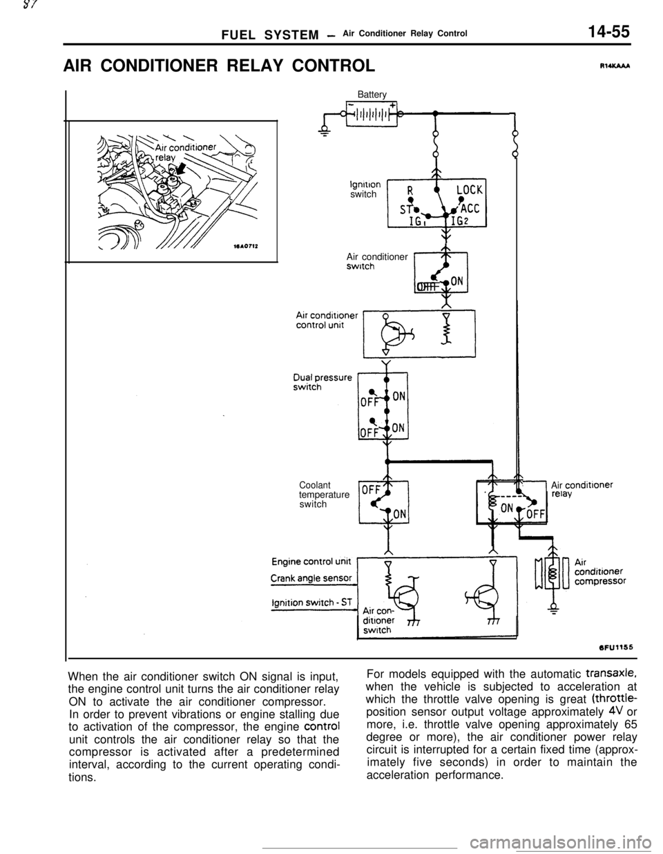
FUEL SYSTEM -Air Conditioner Relay Control14-55AIR CONDITIONER RELAY CONTROL
Batterylgnltlon
switch
Air conditionerswitch
@OFF ON
Coolanttemperature
switch
RlUCAAA
/Air condittoner
When the air conditioner switch ON signal is input,
the engine control unit turns the air conditioner relay
ON to activate the air conditioner compressor.
In order to prevent vibrations or engine stalling due
to activation of the compressor, the engine control
unit controls the air conditioner relay so that the
compressor is activated after a predetermined
interval, according to the current operating condi-
tions.For models equipped with the automatic
transaxle,when the vehicle is subjected to acceleration at
which the throttle valve opening is great (throttle-
position sensor output voltage approximately
4V or
more, i.e. throttle valve opening approximately 65
degree or more), the air conditioner power relay
circuit is interrupted for a certain fixed time (approx-
imately five seconds) in order to maintain the
acceleration performance.
Page 168 of 391
14-56FUEL SYSTEM -Supercharge Pressure Control
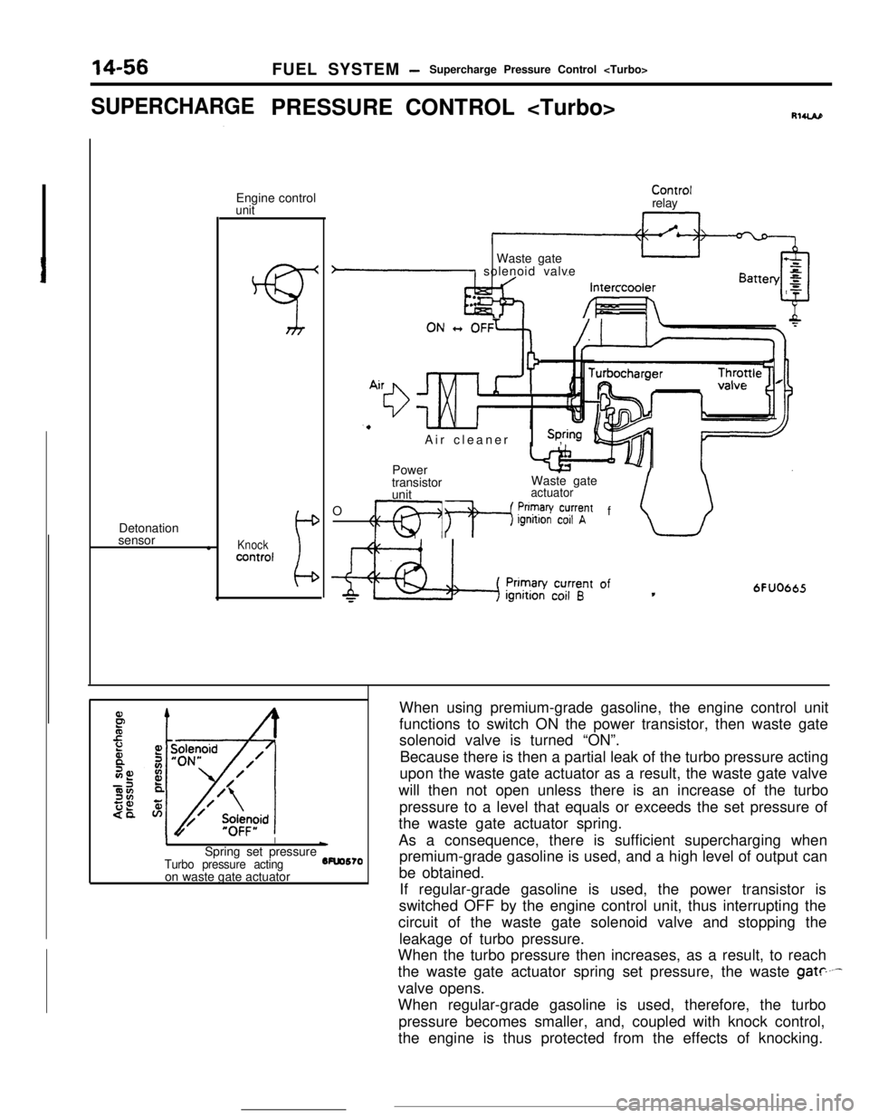
SUPERCHARGEPRESSURE CONTROL
sensor
lEngine control
unit
Knockcontrol
ControlrelayIntercooler
h&l --/I- h
.. .Waste gate
P solenoid valve
Air cleaner,
Power
transistorWaste gate
unit
actuatorOf
CT1 +p$?V~~~t
6FUO665
II\Spring set pressure
Turbo pressure acting5Fuo570
on waste gate actuatorWhen using premium-grade gasoline, the engine control unit
functions to switch ON the power transistor, then waste gate
solenoid valve is turned “ON”.
Because there is then a partial leak of the turbo pressure acting
upon the waste gate actuator as a result, the waste gate valve
will then not open unless there is an increase of the turbo
pressure to a level that equals or exceeds the set pressure of
the waste gate actuator spring.
As a consequence, there is sufficient supercharging when
premium-grade gasoline is used, and a high level of output can
be obtained.
If regular-grade gasoline is used, the power transistor is
switched OFF by the engine control unit, thus interrupting the
circuit of the waste gate solenoid valve and stopping the
leakage of turbo pressure.
When the turbo pressure then increases, as a result, to reach
the waste gate actuator spring set pressure, the waste
gate----valve opens.
When regular-grade gasoline is used, therefore, the turbo
pressure becomes smaller, and, coupled with knock control,
the engine is thus protected from the effects of knocking.
Page 169 of 391
FUEL SYSTEMAir Flow Sensor (AFSI Filter Reset Control
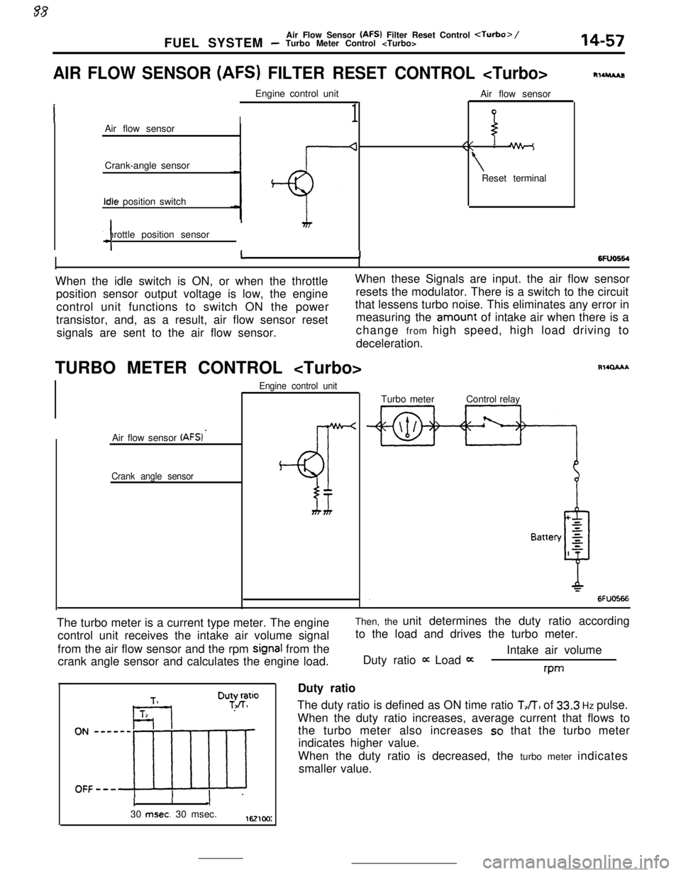
AIR FLOW SENSOR (AFS) FILTER RESET CONTROL
I1Air flow sensor
Crank-angle sensorIdle position switch
Throttle position sensor
4Air flow sensor
//\\ -
\Reset terminal
RllruAs
6FlJo664I11When the idle switch is ON, or when the throttleWhen these Signals are input. the air flow sensor
position sensor output voltage is low, the engineresets the modulator. There is a switch to the circuit
control unit functions to switch ON the powerthat lessens turbo noise. This eliminates any error in
transistor, and, as a result, air flow sensor resetmeasuring the
.amount of intake air when there is a
signals are sent to the air flow sensor.change from high speed, high load driving to
deceleration.
TURBO METER CONTROL
Air flow sensor
(AFSI ’
Crank angle sensorEngine control unit
BT
Rl4QAAATurbo meterControl relay
The turbo meter is a current type meter. The engine
control unit receives the intake air volume signal
from the air flow sensor and the rpm
signal from the
crank angle sensor and calculates the engine load.Then, the unit determines the duty ratio according
to the load and drives the turbo meter.
Intake air volume
Duty ratio
it Load 0:rwDuty ratio
The duty ratio is defined as ON time ratio
TJT, of 33.3 Hz pulse.
When the duty ratio increases, average current that flows to
the turbo meter also increases
so that the turbo meter
indicates higher value.
When the duty ratio is decreased, the turbo meter indicates
smaller value.
cI30
msec. 30 msec.1621cm:
Page 223 of 391
19-12POWER STEERING - Oil Pump
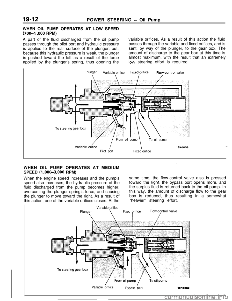
WHEN OIL PUMP OPERATES AT LOW SPEED
(70&l ,000 RPM)
A part of the fluid discharged from the oil pumpvariable orifices. As a result of this action the fluid
passes through the pilot port and hydraulic pressurepasses through the variable and fixed orifices, and is
is applied to the rear surface of the plunger, but,sent, by way of the plunger, to the gear box. The
because this hydraulic pressure is weak, the plungeramount of discharge to the gear box at this time is
is pushed toward the left as a result of the forcealmost maximum, with the result that an extremely
applied by the plunger’s spring, thus opening thelow steering effort is required.
PlungerVariable orificeFixed,orificeFioycontrol valve
/ I
From oil pump
To oil pumpVariable orifice
13POO38-.
Pilot portFixed orifice
.WHEN OIL PUMP OPERATES AT MEDIUM
SPEED
(1 ,OOm,OOO RPM)
When the engine speed increases and the pump’ssame time, the flow-control valve also is pressed
speed also increases, the hydraulic pressure of thetoward the
right, the bypass port opens more, and
fluid discharged from the pump becomes higher,the surplus fluid is returned back to the oil pump. In
overcoming the plunger spring’s force, and causingthis way, the amount of discharge flow to the gear
the plunger to move toward the right. As a result ofbox is reduced, thus resulting in a somewhat
this action, one of the variable orifices closes. At the“heavier” steering effort.
Variable orifice
PlungerFlow-control valve
\\Fixed yrifice/
Variable &iflceBypass ‘LrllJPOO59
Page 227 of 391
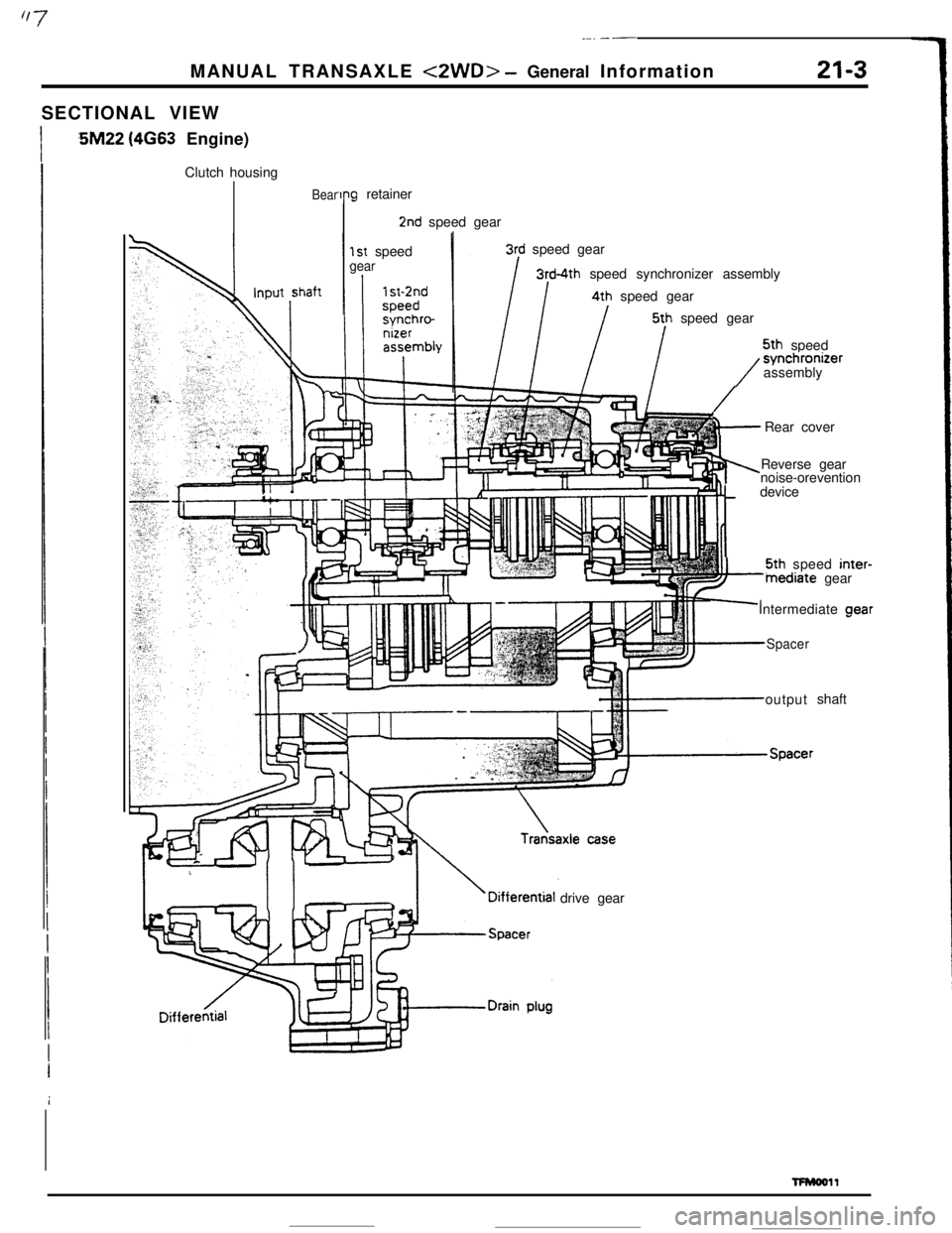
_-. ---MANUAL TRANSAXLE
<2WD> - General Information21-3SECTIONAL VIEW
:5M22 (4663 Engine)
Clutch housing
Bear‘Ing retainer
2nd speed gear
1st speedgear
3rd speed gear
3rd-4th speed synchronizer assembly4th speed gear5th speed gear5th speed
/synchronizer
assembly
ii+-Rear cover
Reverse gear
noise-orevention
tdevice5th speed inter-
inediate gear
Intermediate aear
Spaceroutputshaft
drive gear
TFMooll
Page 232 of 391
_.c.
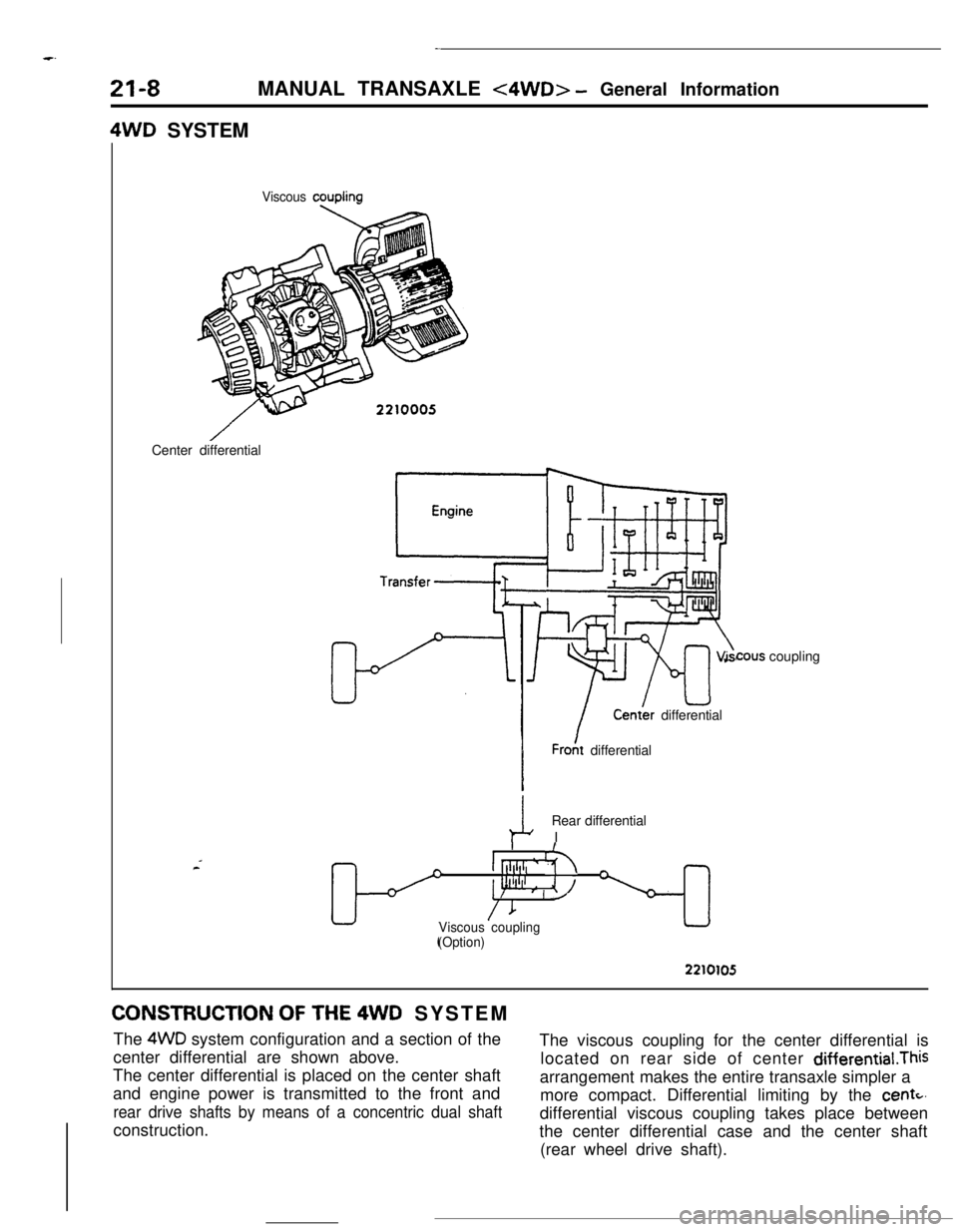
21-8MANUAL TRANSAXLE <4WD> - General Information4WD SYSTEM
Viscous couplingCenter differential
cous coupling
kCenth differential
I
IFro& differential
Rear differential
I
I
I [[lll,i, ‘- h-
1 p’f’ ,* , l/i\
/IViscous couplingL
(Option)
3
2210105CONSTRUCTION
OF THE 4WD SYSTEM
The 4WD system configuration and a section of the
center differential are shown above.The viscous coupling for the center differential is
The center differential is placed on the center shaftlocated on rear side of center differential.This
and engine power is transmitted to the front andarrangement makes the entire transaxle simpler a
rear drive shafts by means of a concentric dual shaftmore compact. Differential limiting by the
centc,construction.differential viscous coupling takes place between
the center differential case and the center shaft
(rear wheel drive shaft).
Page 233 of 391
-MANUAL TRANSAXLE
<4WD> - General information
21-9
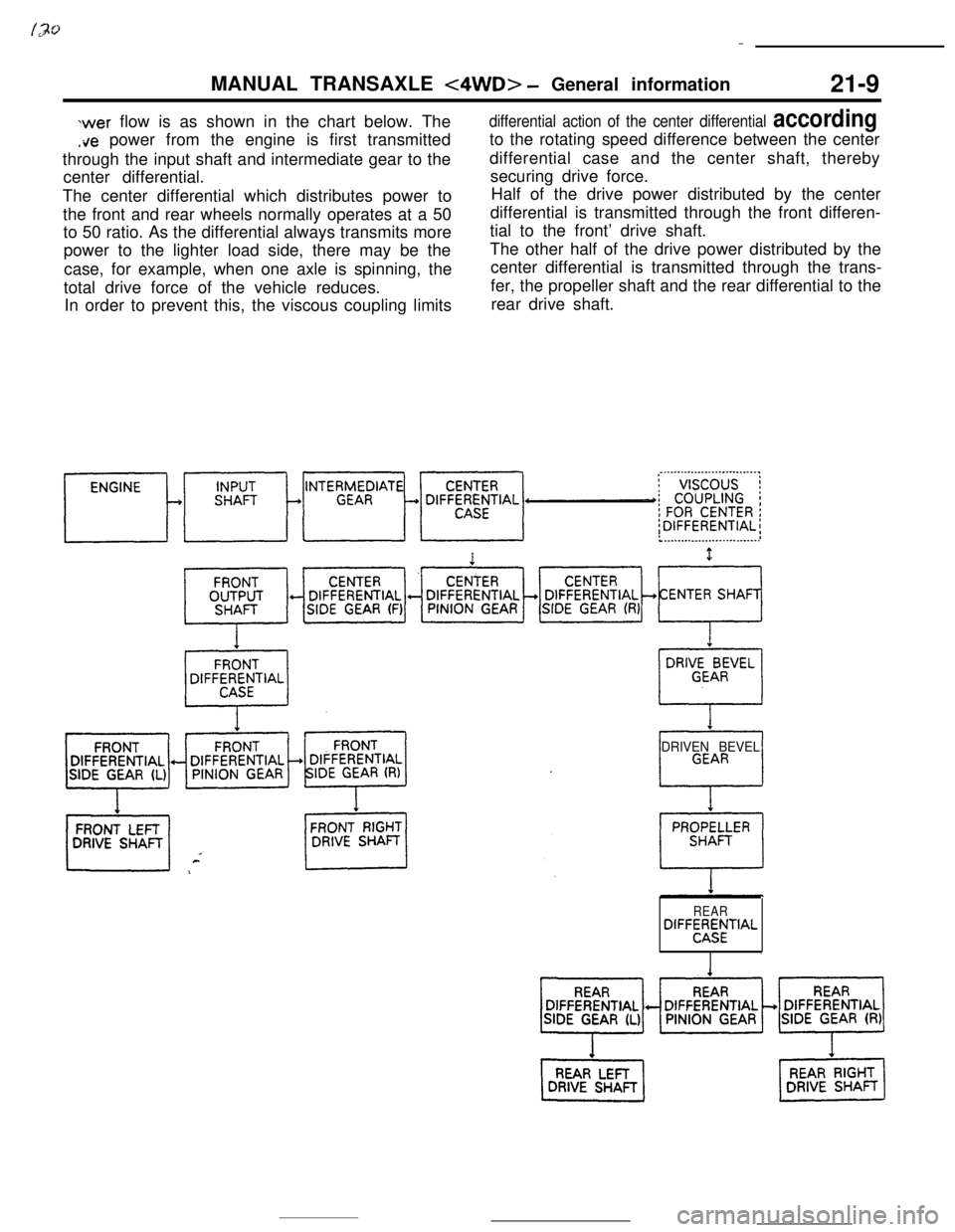
wer flow is as shown in the chart below. The
.ire power from the engine is first transmitted
through the input shaft and intermediate gear to the
center differential.
The center differential which distributes power to
the front and rear wheels normally operates at a 50
to 50 ratio. As the differential always transmits more
power to the lighter load side, there may be the
case, for example, when one axle is spinning, the
total drive force of the vehicle reduces.
In order to prevent this, the viscous coupling limits
differential action of the center differential accordingto the rotating speed difference between the center
differential case and the center shaft, thereby
securing drive force.
Half of the drive power distributed by the center
differential is transmitted through the front differen-
tial to the front’ drive shaft.
The other half of the drive power distributed by the
center differential is transmitted through the trans-
fer, the propeller shaft and the rear differential to the
rear drive shaft.
DRIVEN BEVEL
REARDIFF~;MfTIAL
,
Page 240 of 391
_-
21-16AUTOMATIC TRANSAXLE - General InformationAUTOMATIC
TRANSAXLE
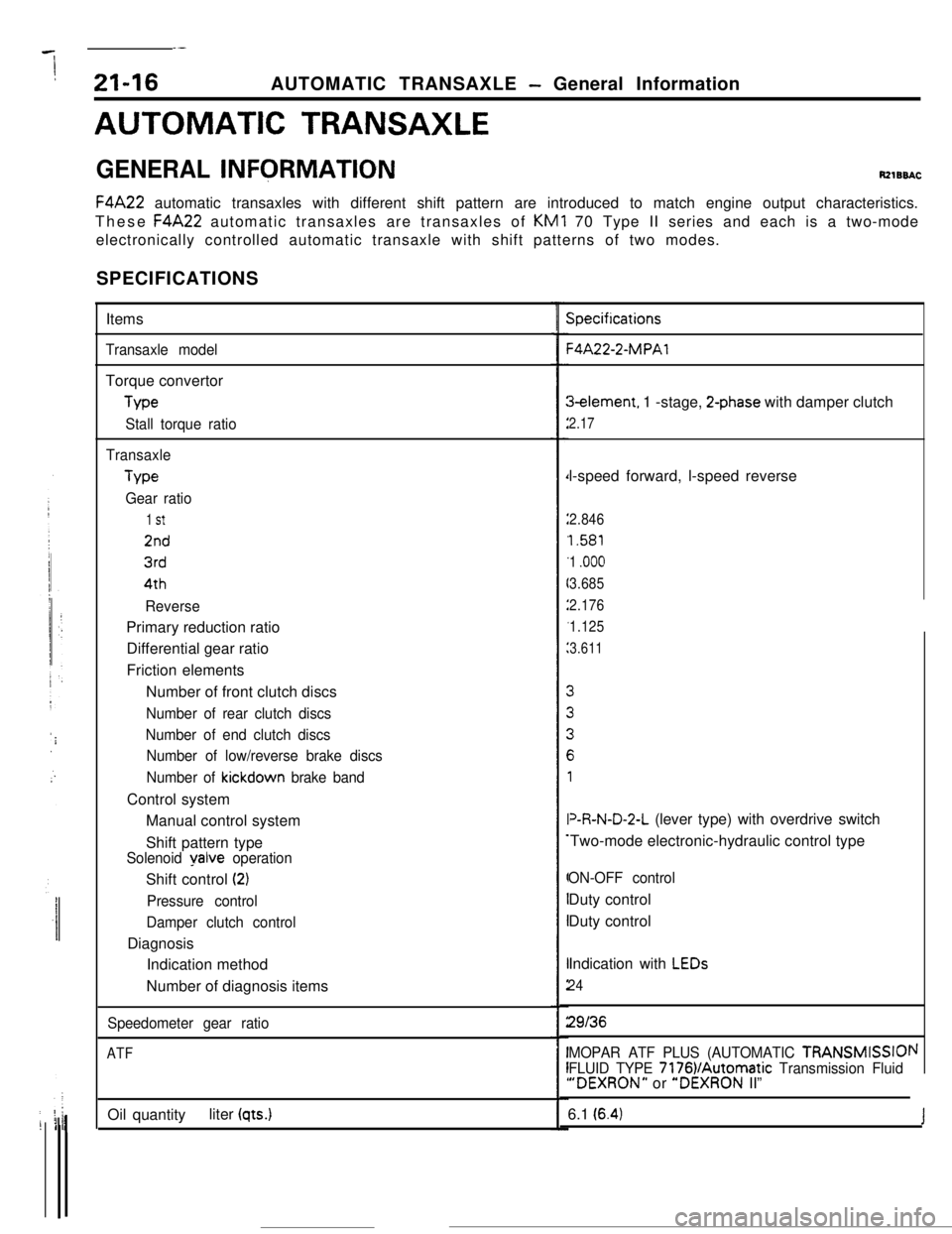
GENERAL INFQRMATIONRzlBBACF4A22 automatic transaxles with different shift pattern are introduced to match engine output characteristics.
These F4A22 automatic transaxles are transaxles of KM1 70 Type II series and each is a two-mode
electronically controlled automatic transaxle with shift patterns of two modes.
SPECIFICATIONS
Items
Transaxle modelTorque convertor
Me
Stall torque ratio
TransaxleType
Gear ratio
1 St
2nd
3rd4th
ReversePrimary reduction ratio
Differential gear ratio
Friction elements
Number of front clutch discs
Number of rear clutch discs
Number of end clutch discs
Number of low/reverse brake discs
Number of
kickdown brake bandControl system
Manual control system
Shift pattern type
Solenoid yalve operationShift control
(2)
Pressure control
Damper clutch controlDiagnosis
Indication method
Number of diagnosis items
Speedometer gear ratio
ATFOil quantityliter
(qts.)
Specifications-4A22-2-MPAl3element, 1 -stage,
2-phase with damper clutch
2.17l-speed forward, l-speed reverse
2.846
1.581
1
.ooo
3.685
2.176
1.125
3.611V&N-D-2-L (lever type) with overdrive switch
Two-mode electronic-hydraulic control type
ON-OFF controlDuty control
Duty control
Indication with
LEDs
24
29136
MOPAR ATF PLUS (AUTOMATIC TRANSMISSIOI
FLUID TYPE 7176VAutomatic Transmission Fluid“DEXRON” or “DEXRON II”
\I6.1
(6.4)J
Page 246 of 391
AUTOMATIC TRANSAXLE - Torque Converter
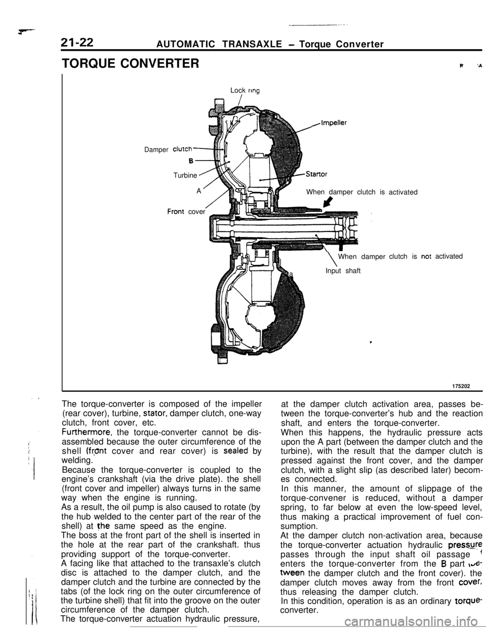
TORQUE CONVERTER
Lock
ring
I
Damper
F
clutch-
B-.Turbine
.AA
/:ront cover
h,Impeller
AStartorWhen damper clutch is
I\When damper
aInput shaftactivated
clutch isactivated
175202The torque-converter is composed of the impeller
(rear cover), turbine,
stator, damper clutch, one-way
clutch, front cover, etc.Furthermore. the torque-converter cannot be dis-
assembled because the outer circumference of the
shell
(front cover and rear cover) is sealed by
welding.
Because the torque-converter is coupled to the
engine’s crankshaft (via the drive plate). the shell
(front cover and impeller) always turns in the same
way when the engine is running.
As a result, the oil pump is also caused to rotate (by
the hub welded to the center part of the rear of the
shell) at the same speed as the engine.
The boss at the front part of the shell is inserted in
the hole at the rear part of the crankshaft. thus
providing support of the torque-converter.
A facing like that attached to the transaxle’s clutch
disc is attached to the damper clutch, and the
damper clutch and the turbine are connected by the
tabs (of the lock ring on the outer circumference of
the turbine shell) that fit into the groove on the outer
circumference of the damper clutch.
The torque-converter actuation hydraulic pressure,at the damper clutch activation area, passes be-
tween the torque-converter’s hub and the reaction
shaft, and enters the torque-converter.
When this happens, the hydraulic pressure acts
upon the A part (between the damper clutch and the
turbine), with the result that the damper clutch is
pressed against the front cover, and the damper
clutch, with a slight slip (as described later) becom-
es connected.
In this manner, the amount of slippage of the
torque-convener is reduced, without a damper
spring, to far below at even the low-speed level,
thus making a practical improvement of fuel con-
sumption.
At the damper clutch non-activation area, because
the torque-converter actuation hydraulic pressure
passes through the input shaft oil passage
-1enters the torque-converter from the
B part &-tween the damper clutch and the front cover). the
damper clutch moves away from the front
cover,thus releasing the damper clutch.
In this condition, operation is as an ordinary torque-
converter.
Page 247 of 391
I,?+7_-AUTOMATIC TRANSAXLE
- Transaxle Mechanism21-23
I IRS SP175003TC
: Torqueconverter
DC : Damper clutchCl : Front clutch
tPlanetan/
gear set
C2 : Rear clutchW : End clutchBl. : Kickdown brake82 : Low/reverse brake
OWC : One-way clutch
FS : Forward sun gearRS : Reverse sun gear
SP : Short pinion
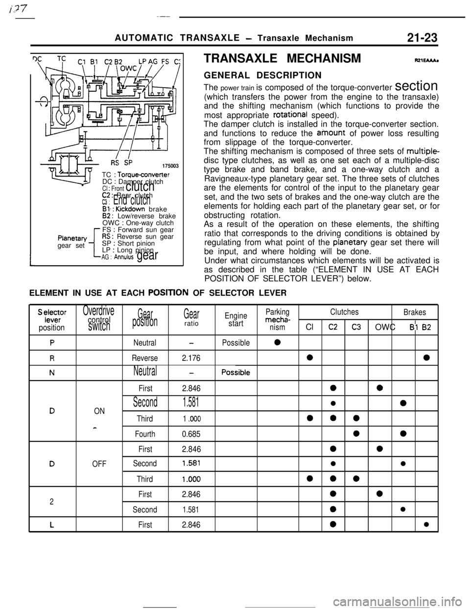
LP : Long pinionAG : Annulus gearTRANSAXLE MECHANISM
fQlEMhGENERAL DESCRIPTION
The power train is composed of the torque-converter section
(which transfers the power from the engine to the transaxle)
and the shifting mechanism (which functions to provide the
most appropriate
rotational speed).
The damper clutch is installed in the torque-converter section.
and functions to reduce the ainount of power loss resulting
from slippage of the torque-converter.
The shifting mechanism is composed of three sets of multiple-
disc type clutches, as well as one set each of a multiple-disc
type brake and band brake, and a one-way clutch and a
Ravigneaux-type planetary gear set. The three sets of clutches
are the elements for control of the input to the planetary gear
set, and the two sets of brakes and the one-way clutch are the
elements for holding each part of the planetary gear set, or for
obstructing rotation.
As a result of the operation on these elements, the shifting
ratio that corresponds to the driving conditions is obtained by
regulating from what point of the
planetan/ gear set there will
be input, and where holding will be done.
Under what circumstances which elements will be activated is
as described in the table (“ELEMENT IN USE AT EACH
POSITION OF SELECTOR LEVER”) below.
ELEMENT IN USE AT EACH
POSITtON OF SELECTOR LEVER
S ylele~rOverdriveGearGearEngineParkingClutches
Brakescontrolmecha-
positionswitchpositionratiostartnismCl c2C3 OWC Bl 82
PNeutral-Possible0
RReverse2.17600
NNeutral-Possible
First
2.8460a
Second1.581l0DON
Third1 .ooo000
e
Fourth0.68500
First2.84600
DOFFSecond1.581ll
Third1 .ooo000
First2.846002
Second1.5810l
LFirst2.8460l