air condition MITSUBISHI ECLIPSE 1990 Service Manual
[x] Cancel search | Manufacturer: MITSUBISHI, Model Year: 1990, Model line: ECLIPSE, Model: MITSUBISHI ECLIPSE 1990Pages: 391, PDF Size: 15.27 MB
Page 3 of 391
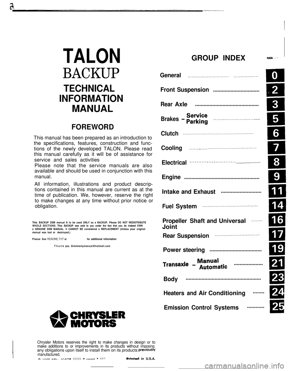
TALON
BACKUP
README.N or for additional information
PreViOUSlVmanufactured.a *-a- .I._..-1-L,.* _____ #Q ^_^__ l L.-Orintul in U.S.A.
GROUP INDEXROSA. - -
General. . . . . . . . . . . . . . . . . . . . . . . . . . . . . .. . . . . . . . . . . . . . . . . .
Front Suspensio n................................
.
Brakes - Eir$rii. . . . . . . . . . . . . . . . . . . . . . . . . . ..s...
Clutch. . . . . . . . . . . . . . . . . . . . . . . . . . . . . . . . . . . . . . . . . . . . . . . . . . . .
Cooling. . . . . . :. . . . .. . . . . . . . . . . . . . . . . . . . . . . . . . . . . . . . . . . .
Electrical. . . . . . . . . . . . . . . . . . . . . . . . . . . ..-..................
Engine....................................................
. . . . . . . . . . . . . . . . . . . . . . . . . . . . . . . . . . . . . . . .
Propeller Shaft and Universal. . . . . . . .
ml
. . . . . . . . . . . . . . . . . . . . . . . . . . . . . . . .
Power steeringCD
ManualTransaxl e - Automatic....................
m
Bodym
Heaters and Air ConditioningRI
A
Emission Control Systems
Page 50 of 391
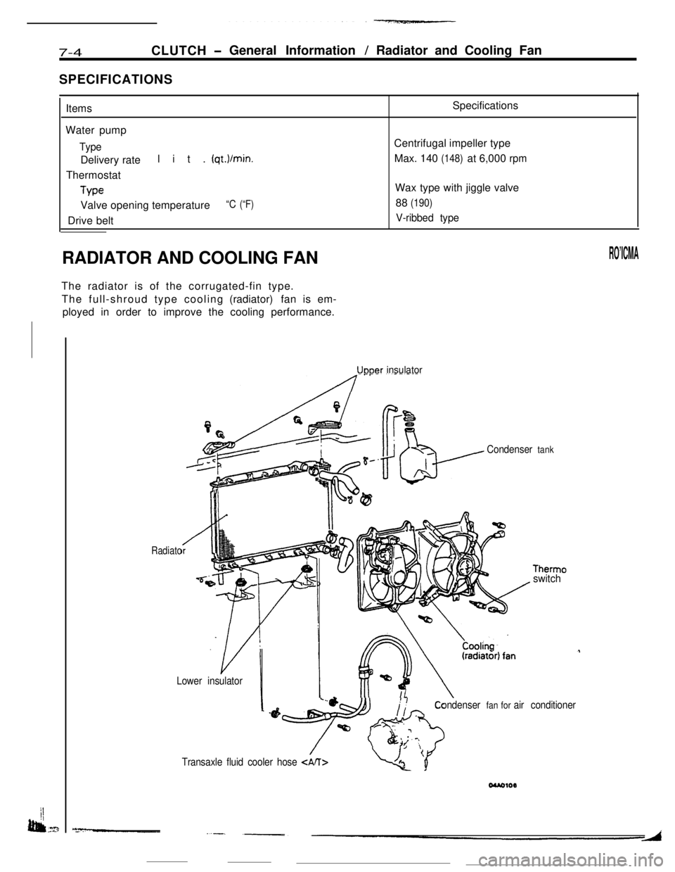
----------------l-~)..
(qt.I/min.
Thermostat
We
Valve opening temperature “C (“F)
Therm0switch
Uooer insulator
Condenser fan for air conditioner
--fyi$f&
/Transaxle fluid cooler hose
Page 55 of 391
ELECTRICAL - Fuses8-3q
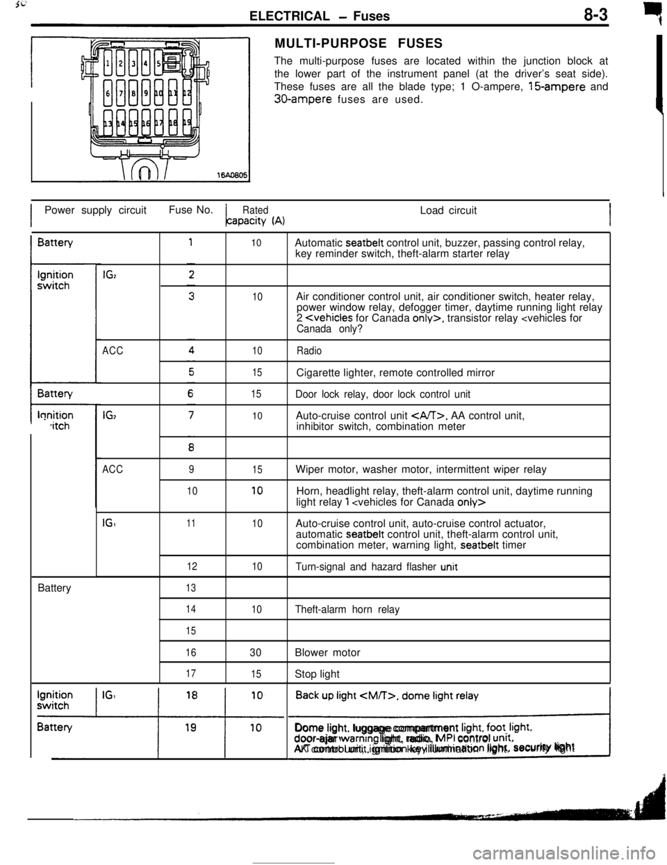
rMULTI-PURPOSE FUSES
The multi-purpose fuses are located within the junction block at
the lower part of the instrument panel (at the driver’s seat side).
These fuses are all the blade type; 1 O-ampere, 15-ampere and
30-ampere fuses are used.
IPower supply circuitFuse No.
RatedLoad circuitapacity
(A)IBattery
t-lonition,itchBattery
IGz
ACC
IG,
10
10
10
15
15
10Automatic seatbelt control unit, buzzer, passing control relay,
key reminder switch, theft-alarm starter relay
Air conditioner control unit, air conditioner switch, heater relay,
power window relay, defogger timer, daytime running light relay
2
Door lock relay, door lock control unitAuto-cruise control unit
, AA control unit,
inhibitor switch, combination meter
ACC
IGI9
1011
12
1315
10
10
10Wiper motor, washer motor, intermittent wiper relay
Horn, headlight relay, theft-alarm control unit, daytime running
light relay
1
automatic seatbelt control unit, theft-alarm control unit,
combination meter, warning light, seatbelt timer
Turn-signal and hazard flasher u.nit
14
15
16
17
10Theft-alarm horn relay
30Blower motor
15Stop light
Back up light
CM/T>, dome light relay
!Dome light. luggage compartment
Irght, foot. Irght.door-ajar warntng light, radio, MPI control unrt.AK control unit, ignition key illumination light.security lightI
Page 56 of 391
_--
8-4ELECTRICAL - Fuses / Diagnosis System
61543
2
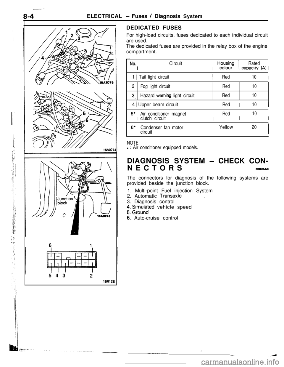
16R133lDEDICATED FUSES
For high-load circuits, fuses dedicated to each individual circuit
are used.
The dedicated fuses are provided in the relay box of the engine
compartment.
No.
I
Circuit
I
H,“d;;-;I
Rated
canacitv (A)I
1 1 Tail light circuitIRedI10I
2Fog light circuitRed10
3,.Hazard warning light circuitRed10
4 ) Upper beam circuitIRedI10I
5’
I
Air conditioner magnet
I
Red
I
10
clutch circuitI
6’Condenser fan motorYellow20
circuitI
NOTEl : Air conditioner equipped models.DIAGNOSIS SYSTEM
- CHECK CON-
NECTORS
nmcwaBThe connectors for diagnosis of the following systems are
provided beside the junction block.
1. Multi-point Fuel injection System
2. Automatic
Transaxle.3. Diagnosis control
z. grm.rlnaFd vehicle speed
6: Auto-cruise control
:..--.-__-.
Page 63 of 391
1ELECTRICAL
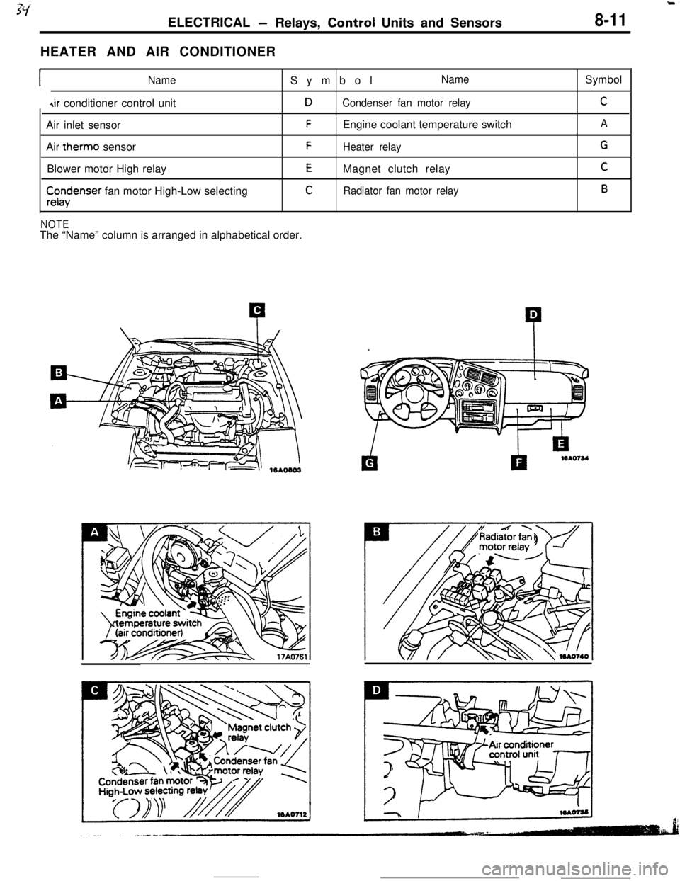
-Relays, Control Units and Sensors8-11HEATER AND AIR CONDITIONER
INameSymbolName
4ir conditioner control unitDCondenser fan motor relayAir inlet sensor
FEngine coolant temperature switch
Air therm0 sensor
FHeater relayBlower motor High relay
EMagnet clutch relay
$x$enser fan motor High-Low selectingCRadiator fan motor relay
NOTEThe “Name” column is arranged in alphabetical order.Symbol
C
A
G
C
B
Page 79 of 391
-----. _-- ___ELECTRICAL
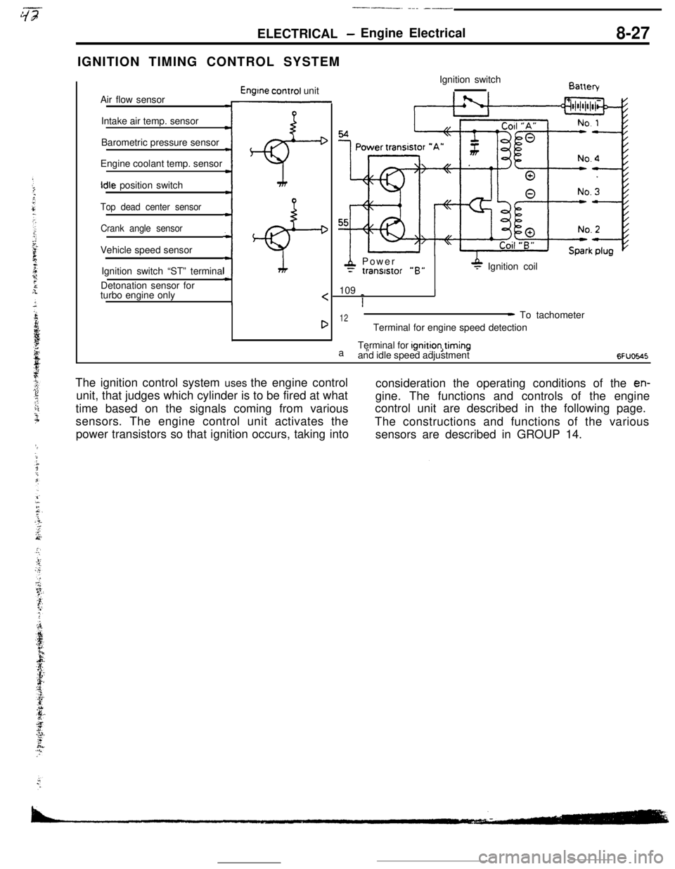
- Engine Electrical8-27IGNITION TIMING CONTROL SYSTEM
Air flow sensor
Engtne control unit
Intake air temp. sensor
Barometric pressure sensor
Engine coolant temp. sensorIdle position switch
:+
Top dead center sensor
Crank angle sensorVehicle speed sensor
;+Ignition switch “ST” terminal
Detonation sensor for
turbo engine only
4 Power= tranststor “B”P Ignition coil
109
_
I
1
12a”- To tachometer
Terminal for engine speed detection
Terminal for ignition,timing
and idle speed adjustment
6FUoE.45The ignition control system uses the engine control
consideration the operating conditions of the
en-unit, that judges which cylinder is to be fired at what
gine. The functions and controls of the engine
time based on the signals coming from variouscontrol unit are described in the following page.
sensors. The engine control unit activates the
The constructions and functions of the various
power transistors so that ignition occurs, taking into
sensors are described in GROUP 14.
Page 80 of 391
8-28ELECTRICAL- Engine Electrical
IGNITION TIMING CONTROL
Reading of Input signallgnitlon power
distribution control
(selection of power
transistor actlvatlon)Control mode
I II II IControl mode
dectsion data
Basic energlzatlon
I’
Engine control unitPower
Powertranststor “A”tranststor “B”
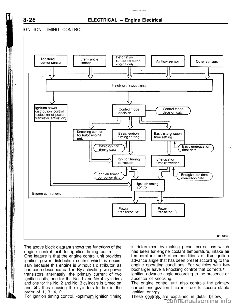
6ELOO66The above block diagram shows the
fljnctions of the
engine control unit for ignition timing control.
One feature is that the engine control unit provides
ignition power distribution control which is neces-
sary because this engine is without a distributor, as
has been described earlier. By activating two power
transistors alternately, the primary current of two
ignition coils, one for the No. 1 and No.4 cylinders
and one for the No. 2 and No, 3 cylinders is turned onand
off. thus causing the cylinders to fire in the
order of 1, 3, 4, 2.
For ignition timing control, -optimum ignition timing.^--_
_. -.is determined by making preset corrections which
has been for engine coolant temperature, intake air
temperature an& other conditions of the ignition
advance angle that has been preset according to the
engine operating conditions. For vehicles with
tur=_.bocharger have a knocking control that corrects tl
ignition advance angle according to the presence or
absence of knocking.
The engine control unit also controls the primary
current energization time in order to secure stable
ignition energy.
These controls are explained in detail below.
--. .----- ---- --- ___. .-. ___.,.__
Page 82 of 391
8-30ELECTRICAL - Engine Electrical
Ignition Advance Angle Control
While
cranking
Fixed angle(5”BTD.C)Engme coolantBarometnc‘-Intake air 1temperaturepressuretemperaturesensorsensor, sensor
Dunng normal operatlon4i+
Advance angle map valueEngine
coolantBarometricIntake airaccording to engine speed4and intake air volumetemperature- pressure__c temperature 4
correctioncorrectloncorrectton
Durtng ignition tlmmg adjustment
Fixed angle(5”BTDC)
c
=ower transistor
-$To ignition
coil
s
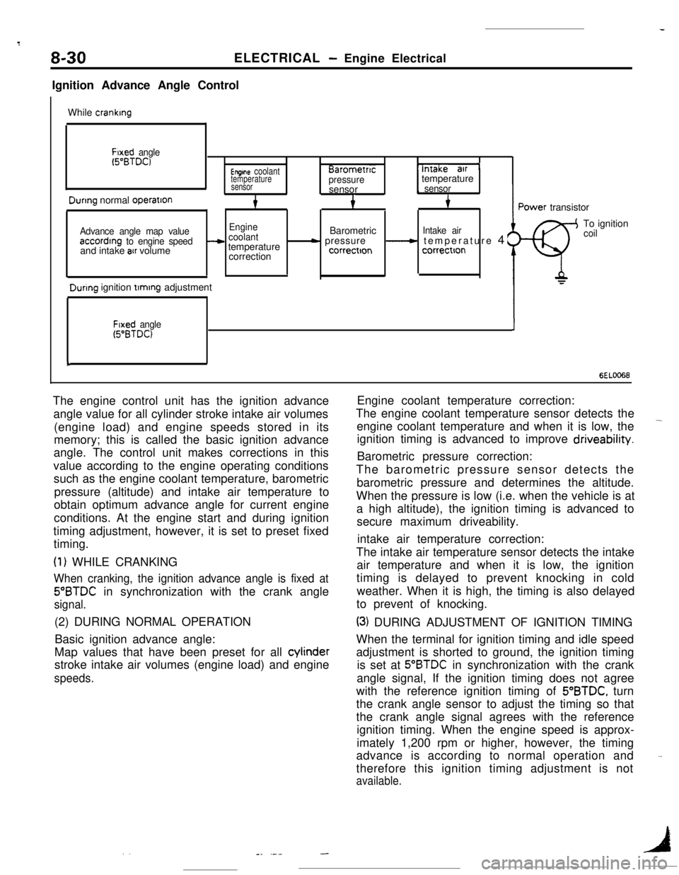
6EL0066The engine control unit has the ignition advance
angle value for all cylinder stroke intake air volumes
(engine load) and engine speeds stored in its
memory; this is called the basic ignition advance
angle. The control unit makes corrections in this
value according to the engine operating conditions
such as the engine coolant temperature, barometric
pressure (altitude) and intake air temperature to
obtain optimum advance angle for current engine
conditions. At the engine start and during ignition
timing adjustment, however, it is set to preset fixed
timing.
(1) WHILE CRANKING
When cranking, the ignition advance angle is fixed at
5”BTDC in synchronization with the crank angle
signal.(2) DURING NORMAL OPERATION
Basic ignition advance angle:
Map values that have been preset for all cylinder
stroke intake air volumes (engine load) and engine
speeds.Engine coolant temperature correction:
The engine coolant temperature sensor detects the
engine coolant temperature and when it is low, the
-ignition timing is advanced to improve driveability.
Barometric pressure correction:
The barometric pressure sensor detects the
barometric pressure and determines the altitude.
When the pressure is low (i.e. when the vehicle is at
a high altitude), the ignition timing is advanced to
secure maximum driveability.
intake air temperature correction:
The intake air temperature sensor detects the intake
air temperature and when it is low, the ignition
timing is delayed to prevent knocking in cold
weather. When it is high, the timing is also delayed
to prevent of knocking.
(3) DURING ADJUSTMENT OF IGNITION TIMING
When the terminal for ignition timing and idle speed
adjustment is shorted to ground, the ignition timing
is set at
5”BTDC in synchronization with the crank
angle signal, If the ignition timing does not agree
with the reference ignition timing of 5’BTDC, turn
the crank angle sensor to adjust the timing so that
the crank angle signal agrees with the reference
ignition timing. When the engine speed is approx-
imately 1,200 rpm or higher, however, the timing
advance is according to normal operation and
therefore this ignition timing adjustment is not
available.
-
. .1-_ .---
Page 97 of 391
9-12
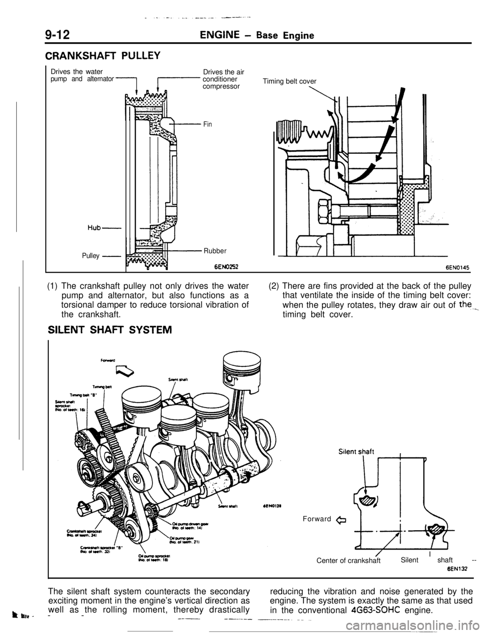
CRANKSHAFT PULLEY
ENGINE- Base EngineDrives the water
pump and alternator
Hub-
Pulley -Drives the air
conditioner
compressor
Fin
Rubber
6EMI2526EN0145 Timing belt cover
(1) The crankshaft pulley not only drives the water
pump and alternator, but also functions as a
torsional damper to reduce torsional vibration of
the crankshaft.
SILENT SHAFT SYSTEM(2) There are fins provided at the back of the pulley
that ventilate the inside of the timing belt cover:
when the pulley rotates, they draw air out of the._
timing belt cover.
Forward
@
/I
Center of crankshaftSilent shaft --
6ENl32The silent shaft system counteracts the secondaryreducing the vibration and noise generated by the
exciting moment in the engine’s vertical direction asengine. The system is exactly the same as that used
t uluv -well as the rolling moment, thereby drastically
in the conventional 4G63-SOHC engine.
-------_---.--- __.----_. _... ,.
Page 114 of 391
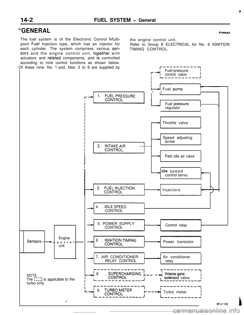
sors and the engine control unit, tooether with
actuators and
related components, and k controlled
according to nine control functions as shown below.
Of these nine, No.
1 and, Nos. 3 to 9 are supplied by
II
EngineSensors - control -unit
r--------‘-1
l--cIFuel-pressureIcontrol valveII
‘4 Fuel DumoI13 I I or-’I
,--c 1. ;;EILT!I;ELSSURE1J
Fuel presJ1regulatorI
- Throttle valve
i
7
_c Speed adjusting
screw
14-2
“GENERALFUEL SYSTEM
- GeneralRl484AB
The fuel system is of the Electronic Control
Multi-point Fuel Injection type, which has an injector forthe engine control unit.
each cylinder. The system comprises various sen-Refer to Group 8 ELECTRICAL for No. 6 IGNITION
TIMING CONTROL.
-Fast idle air valve
- idle speed
control servo-
IrI
- Injectors
- 4. IOLESPEEO
CONTROL
-I5. POWER SUPPLYCONTROLControl relay
-) 6. V$&iRq3NLTIMING- Power transistor
b
-c 7. AIR CONDITIONERRELAY CONTROL- Air conditioner
relay
c-------------Tp----------1
NOTEI
The [‘-,l> is applicable to theI
.-( 8. ZJJ\~RR~LARGING k-- -4 Wastepate
Liturbo only.-----w--------IL solenoid valve--B--------d
Ir-‘---‘---“‘-7c------v--w-1
L’ 9.
-I
‘C;RB;zLETER--A Turbo meterI--------c----J+ L----------a
k’6FU1145