relay MITSUBISHI ECLIPSE 1990 Service Manual
[x] Cancel search | Manufacturer: MITSUBISHI, Model Year: 1990, Model line: ECLIPSE, Model: MITSUBISHI ECLIPSE 1990Pages: 391, PDF Size: 15.27 MB
Page 46 of 391
-. ..- ,..__ _. I-., . . . . -. . “-Ix.. ...~‘,.;;&;,-*~;
CLUTCH- Clutch Control6-3
-
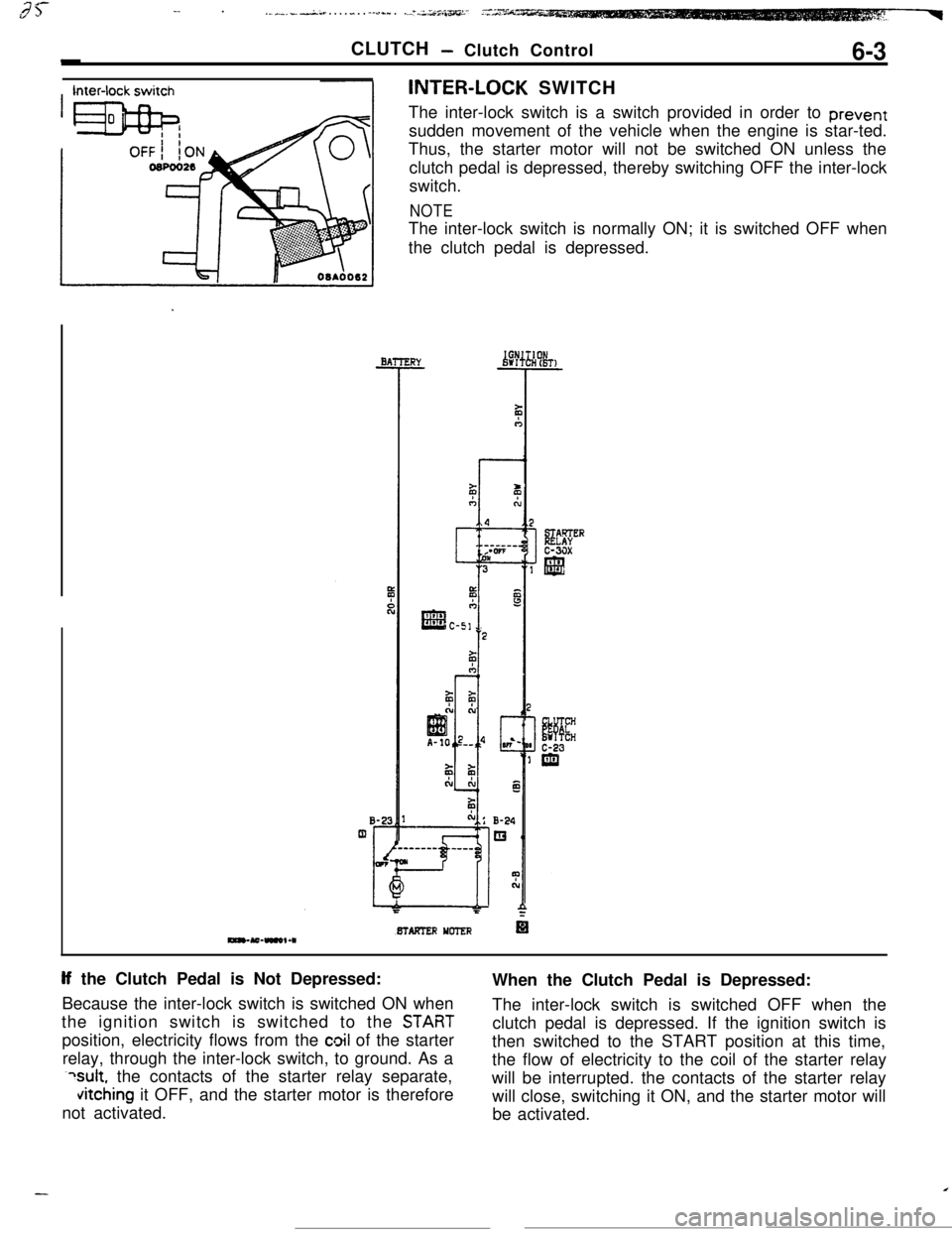
Inter-lock switchINTER-LOCK SWITCH
The inter-lock switch is a switch provided in order to prevent
sudden movement of the vehicle when the engine is star-ted.
BTAFTER YCTER
If the Clutch Pedal is Not Depressed:
Because the inter-lock switch is switched ON when
STABT
position, electricity flows from the cloil of the starter
relay, through the inter-lock switch, to ground. As a
?sult, the contacts of the starter relay separate,
vitching it OFF, and the starter motor is therefore
not activated.
Page 53 of 391
ELECTRICAL
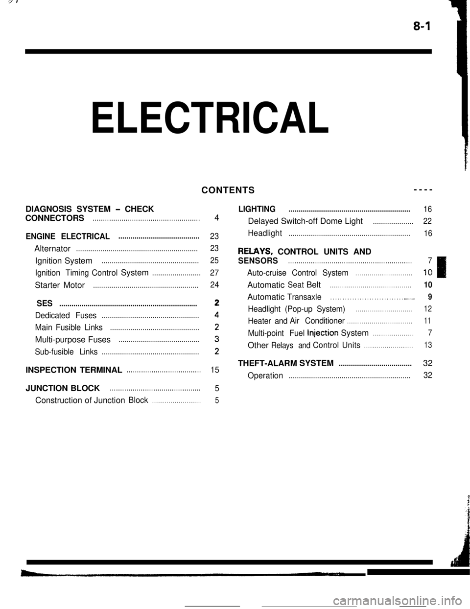
REUYS, CONTROL UNITS AND
SENSORS . . . . . . . . . . . . . . . . . . . . . . . . . . . . . . . . . . . . \
. . . . . . . . . . . . . . . . . . . . . . . .
.._.......
Headlight (Pop-up System) . . . . . . . . . . . . . . . . . . . . . . . . . . . .
InjectionSystem. . . . . . . . . . . . . . . . . . . .
OtherRelays an dControlUnit s. . . . . . . . . . . . . . . . . . . . . . . .
10
10
Page 54 of 391
8-2
IBlueI20
L
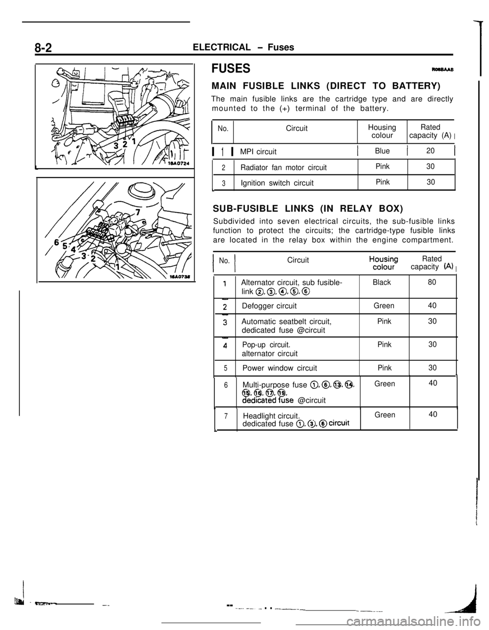
SUB-FUSIBLE LINKS (IN RELAY BOX)
I I
No. CircuitHcyyRated
(A)I
0, 0, @, 0, @
Defogger circuit
1
6 Multi-purpose fuse 0. @. 0. @.Green 40
!Fed%$?&e @circuit1
7 Headlight circuit.0. @I. @circuitL
Ib&i -e?z5mm..-_-- -.--- --..._ . . __-___-----_4
Page 55 of 391
ELECTRICAL - Fuses8-3q
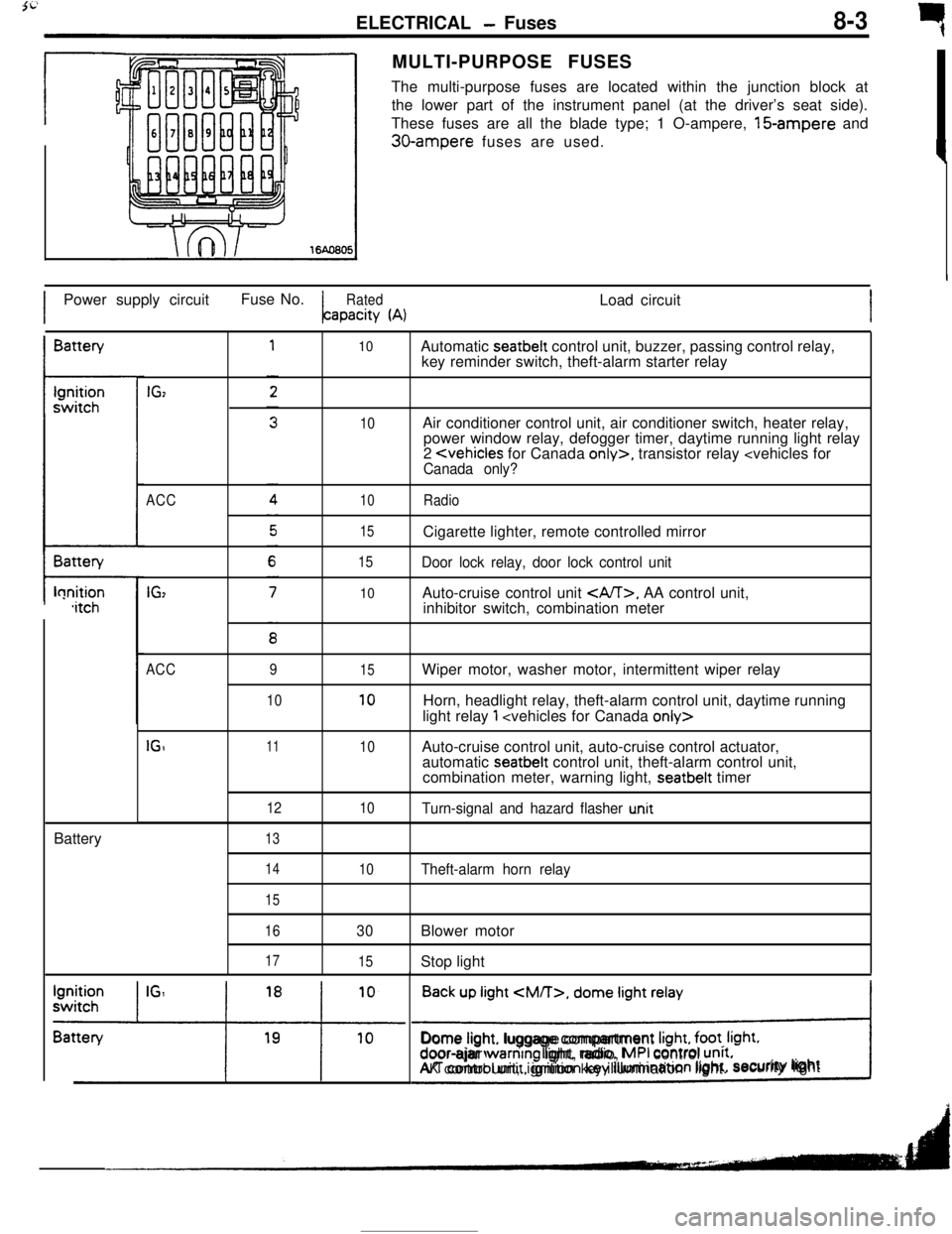
rMULTI-PURPOSE FUSES
The multi-purpose fuses are located within the junction block at
the lower part of the instrument panel (at the driver’s seat side).
These fuses are all the blade type; 1 O-ampere, 15-ampere and
30-ampere fuses are used.
IPower supply circuitFuse No.
RatedLoad circuitapacity
(A)IBattery
t-lonition,itchBattery
IGz
ACC
IG,
10
10
10
15
15
10Automatic seatbelt control unit, buzzer, passing control relay,
key reminder switch, theft-alarm starter relay
Air conditioner control unit, air conditioner switch, heater relay,
power window relay, defogger timer, daytime running light relay
2
Door lock relay, door lock control unitAuto-cruise control unit
, AA control unit,
inhibitor switch, combination meter
ACC
IGI9
1011
12
1315
10
10
10Wiper motor, washer motor, intermittent wiper relay
Horn, headlight relay, theft-alarm control unit, daytime running
light relay
1
automatic seatbelt control unit, theft-alarm control unit,
combination meter, warning light, seatbelt timer
Turn-signal and hazard flasher u.nit
14
15
16
17
10Theft-alarm horn relay
30Blower motor
15Stop light
Back up light
CM/T>, dome light relay
!Dome light. luggage compartment
Irght, foot. Irght.door-ajar warntng light, radio, MPI control unrt.AK control unit, ignition key illumination light.security lightI
Page 56 of 391
_--
8-4ELECTRICAL - Fuses / Diagnosis System
61543
2
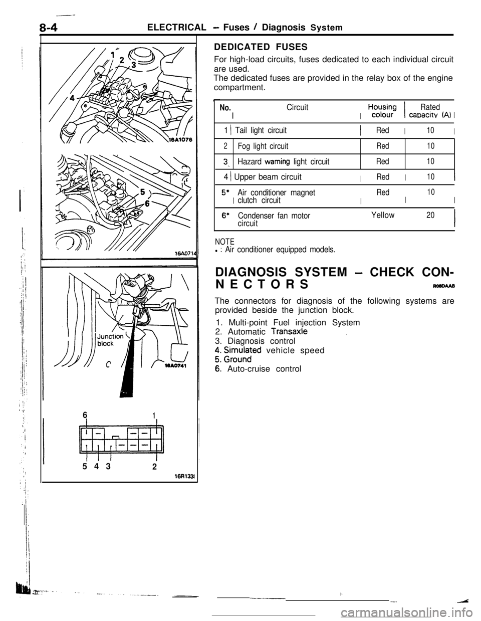
16R133lDEDICATED FUSES
For high-load circuits, fuses dedicated to each individual circuit
are used.
The dedicated fuses are provided in the relay box of the engine
compartment.
No.
I
Circuit
I
H,“d;;-;I
Rated
canacitv (A)I
1 1 Tail light circuitIRedI10I
2Fog light circuitRed10
3,.Hazard warning light circuitRed10
4 ) Upper beam circuitIRedI10I
5’
I
Air conditioner magnet
I
Red
I
10
clutch circuitI
6’Condenser fan motorYellow20
circuitI
NOTEl : Air conditioner equipped models.DIAGNOSIS SYSTEM
- CHECK CON-
NECTORS
nmcwaBThe connectors for diagnosis of the following systems are
provided beside the junction block.
1. Multi-point Fuel injection System
2. Automatic
Transaxle.3. Diagnosis control
z. grm.rlnaFd vehicle speed
6: Auto-cruise control
:..--.-__-.
Page 57 of 391
3i
ELECTRICAL - Junction Block8-5JUNCTION
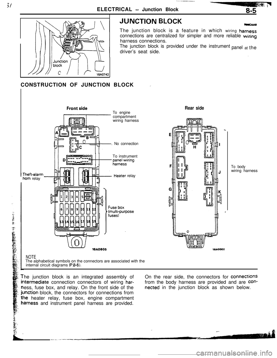
BLOCKThe junction block is a feature in which wiring
hamess
connections are centralized for simpler and more reliable wiringharness connections.
The junction block is provided under the instrumentdriver’s seat side.panelat the
CONSTRUCTION OF JUNCTION BLOCK
_.rheft-alarm
iom relay
To enginecompartment
wiring harness
. No connectionTo instrument
;;;+$ring
.’ ./%A0805relay
Rear side
NOTEThe alphabetical symbols on the connectors are associated with the
internal circuit diagrams
(PB-6).To bodywiring harness
he junction block is an integrated assembly ofltermediate connection connectors of wiring
har-ess, fuse box, and relay. On the front side of the
unction block, the connectors for connections from
le heater relay, fuse box, engine compartment
amess and instrument panel harness are provided.On the rear side, the connectors for connections
from the body harness are provided and are
con-
netted in the junction block as shown below.
Page 59 of 391
ELECTRICAL -Relavs, Control Units and Sensors
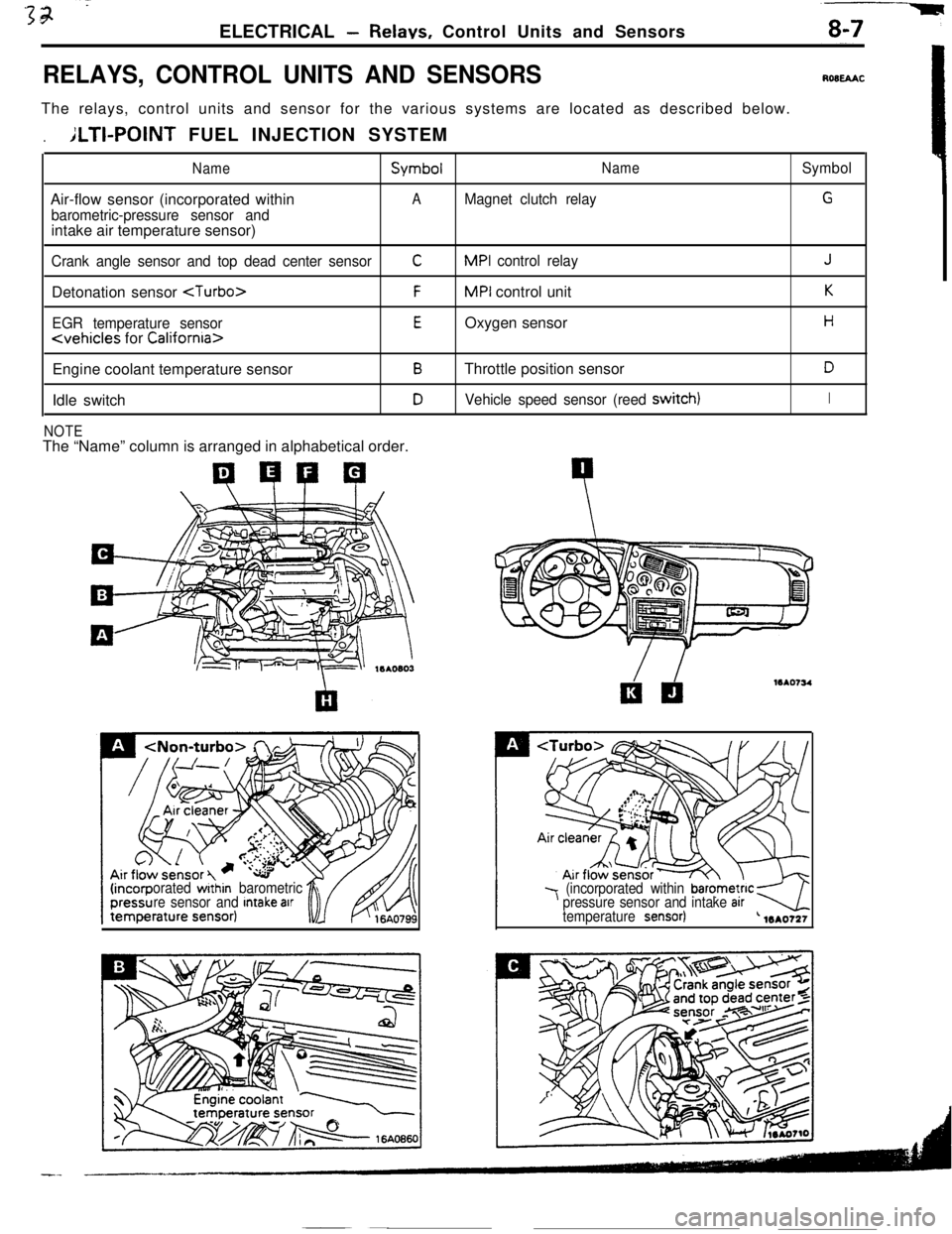
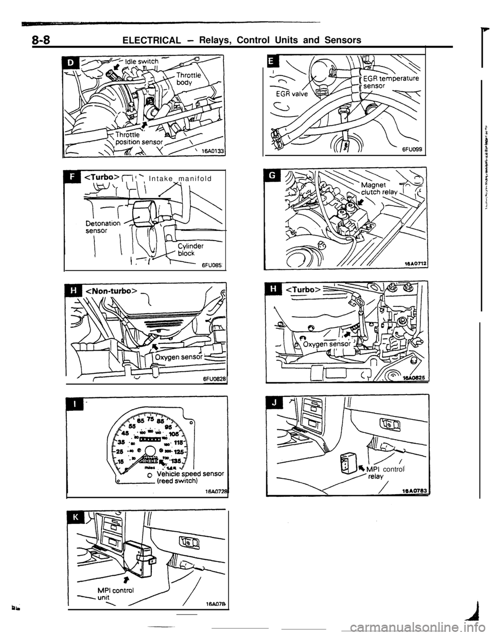
RELAYS, CONTROL UNITS AND SENSORSROBEAACThe relays, control units and sensor for the various systems are located as described below.
.ILTI-POINT FUEL INJECTION SYSTEM
NameSymbolNameSymbolAir-flow sensor (incorporated within
AMagnet clutch relayG
barometric-pressure sensor andintake air temperature sensor)
Crank angle sensor and top dead center sensorCMPI control relayJDetonation sensor
EGR temperature sensorEOxygen sensorH
Engine coolant temperature sensor
BThrottle position sensorDIdle switch
DVehicle speed sensor (reed switch)I
NOTEThe “Name” column is arranged in alphabetical order.
orated within barometric
re sensor and Intake arr7 (incorporated within barometnc kpressure sensor and intake arrtemperature sensor)-4L 1mo721
Page 60 of 391
8-8ELECTRICAL -Relays, Control Units and Sensors
1, lyJJrI-
I .I
6FlJO85Z
I
/7~ 1J -6FUO8281
b MPI control
Page 61 of 391
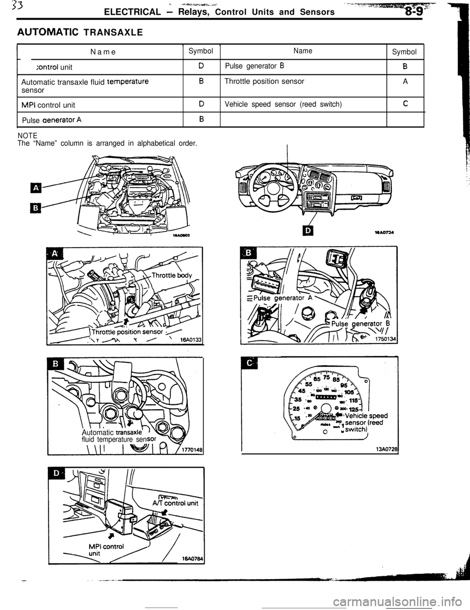
33.- .1S~IUlj~%L...i-.ELECTRICAL
- Relays, Control Units and Sensors
AUTOMATiC TRANSAXLE
Name:ontroi unit
Automatic transaxle fluid temperature
sensorMPI control unit
Pulse aenerator A
SymbolNameSymbol
DPulse generator BB
BThrottle position sensor
A
DVehicle speed sensor (reed switch)C
B
NOTEThe “Name” column is arranged in alphabetical order.
Automatic
transaxlfluid temperature sen
16440784
13AO721
Page 62 of 391
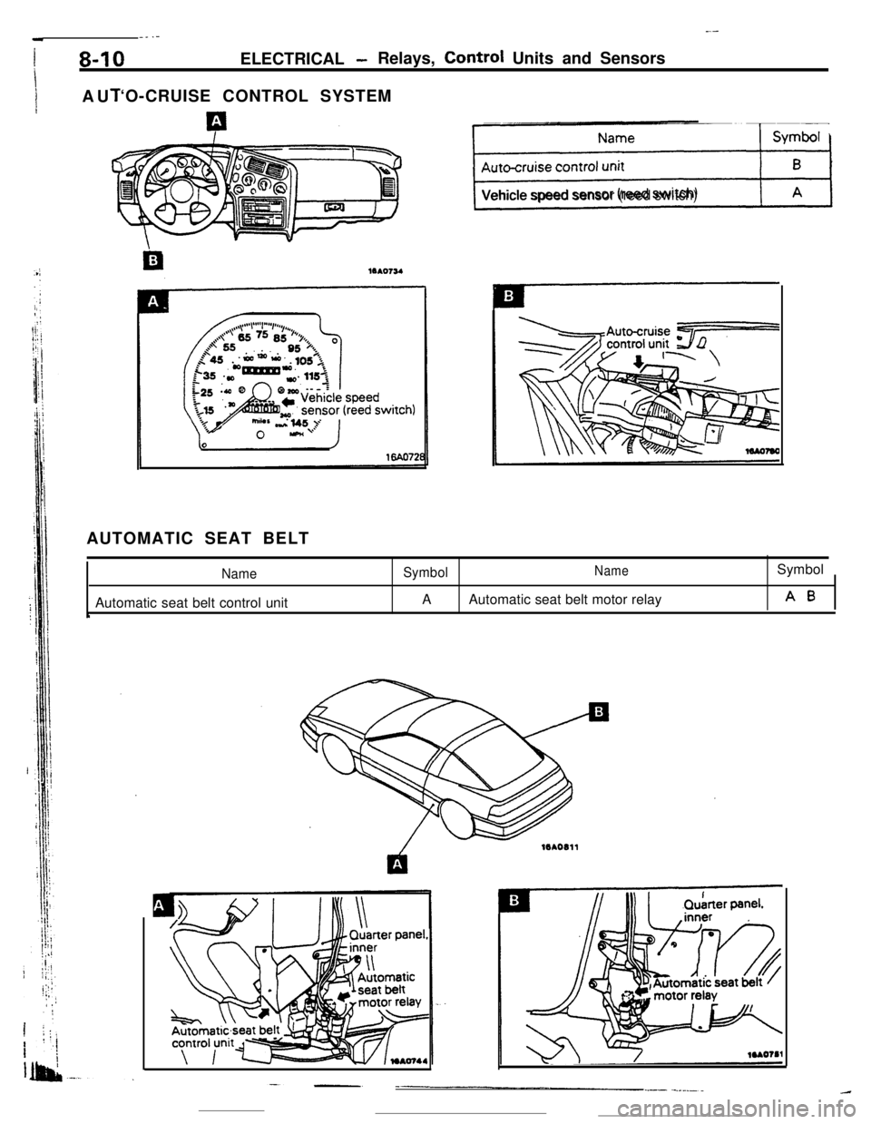
_--__ .-
I8-10ELECTRICAL -Relays, Control Units and Sensors
I
1AUI‘O-CRUISE CONTROL SYSTEM
ps+%JVehicle speed sensor (reed switch)
AUTOMATIC SEAT BELT
NameAutomatic seat belt control unit
‘
SymbolNameSymbol
AAutomatic seat belt motor relay
A0