engine coolant MITSUBISHI ECLIPSE 1990 Owner's Manual
[x] Cancel search | Manufacturer: MITSUBISHI, Model Year: 1990, Model line: ECLIPSE, Model: MITSUBISHI ECLIPSE 1990Pages: 391, PDF Size: 15.27 MB
Page 153 of 391
FUEL SYSTEM -Fuel Injection Control
14-41
During normal operation (including idling), the en-
gine control unit controls the injector activation time
tcThieve the stoichiometric air/fuel ratio, which
e.;res maximum efficiency of the catalytic conver-
ter, on the basis of the oxygen sensor signal.
When the air/fuel mixture is richer than the
stoichiometric ratio, there is less oxygen in the
exhaust gas and thus the oxygen sensor output
voltage is higher; hence a “mixture rich” signal is
input to the engine control unit. Then, the engine
control unit decreases the amount of fuel injected. If
the air/fuel ratio decreases to the point that and the
mixture becomes leaner than the stoichiometric
ratio, the oxygen concentration in the exhaust gas
increases and the oxygen sensor output voltage
becomes lower. Then, a “mixture lean” signal isinput to the engine control unit.
Upon input of this signal, the engine control unit
increases the feedback correction factor, thus caus-
ing more fuel to be injected.
By means of the above-mentioned controls (collec-
tively called “feedback control”), the air-fuel mixture
is maintained at the stoichiometric ratio.
Under the following specific conditions, this feed-
back control is not performed, in order to improve
driveability.
(11
(2)
::I
(5)While cranking the engine
During engine warm-up when engine coolant
temperature is less than
45°C (113°F)During acceleration/deceleration
During high load operation
When oxygen sensor is not functioning
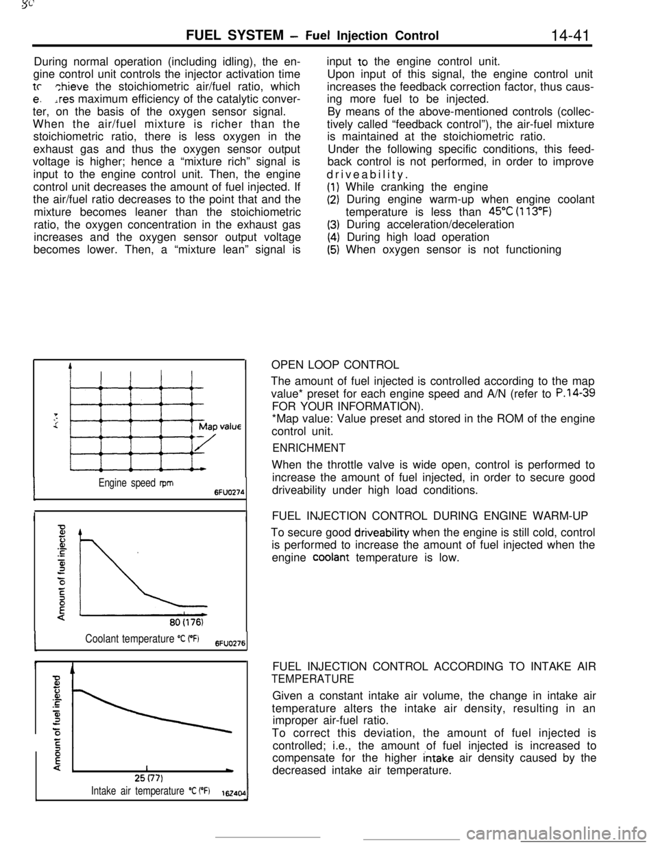
IOPEN LOOP CONTROL
Engine speed rpm6FUO274
II
80(176)
Coolant temperature “C (“Fj6FlJO276
I425(77)
Intake air temperature “C (“F)1~40,0IThe amount of fuel injected is controlled according to the map
value* preset for each engine speed and A/N (refer to
P.l4-39FOR YOUR INFORMATION).
*Map value: Value preset and stored in the ROM of the engine
control unit.
ENRICHMENTWhen the throttle valve is wide open, control is performed to
increase the amount of fuel injected, in order to secure good
driveability under high load conditions.
FUEL INJECTION CONTROL DURING ENGINE WARM-UP
To secure good driveability when the engine is still cold, control
is performed to increase the amount of fuel injected when the
engine
cooiant temperature is low.
FUEL INJECTION CONTROL ACCORDING TO INTAKE AIR
TEMPERATUREGiven a constant intake air volume, the change in intake air
temperature alters the intake air density, resulting in an
improper air-fuel ratio.
To correct this deviation, the amount of fuel injected is
controlled; i.e., the amount of fuel injected is increased to
compensate for the higher
intake air density caused by the
decreased intake air temperature.
Page 154 of 391
14-42
FUEL SYSTEM- Fuel Injection Control
4
Fz.or.c
4:0/
E
{!*760 (301Barometric pressure
mmHg (in.Hg) 6Fuo9z
c
Timet
6FUO279Drivecurrent
0: bri
F2JJ’ ipe; II
I+-JValve opening timi16240:
E‘C
F
.-
is
3
3:\Battery voltage
V162406
80 (176)Coolant temperature
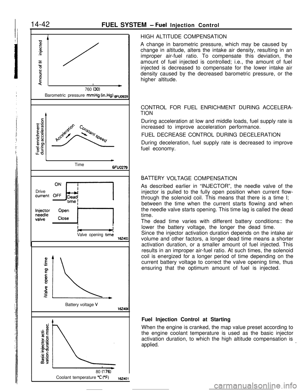
“C (“F)162401HIGH ALTITUDE COMPENSATION
A change in barometric pressure, which may be caused by
change in altitude, alters the intake air density, resulting in an
improper air-fuel ratio. To compensate this deviation, the
amount of fuel injected is controlled; i.e., the amount of fuel
injected is decreased to compensate for the lower intake air
density caused by the decreased barometric pressure, or the
higher altitude.
CONTROL FOR FUEL ENRICHMENT DURING ACCELERA-
TIONDuring acceleration at low and middle loads, fuel supply rate is
increased to improve acceleration performance.
FUEL DECREASE CONTROL DURING DECELERATION
During deceleration, fuel supply rate is decreased to improve
fuel economy.
BATTERY VOLTAGE COMPENSATION
As described earlier in “INJECTOR”, the needle valve of the
injector is pulled to the fully open position when current flow-
through the solenoid coil. This means that there is a time I;
between the time when the current starts flowing and when
the needle valve starts opening. This time lag is called the dead
time.
The dead time varies with different battery conditions:: the
lower the battery voltage, the longer the dead time.
Since the injector activation duration depends on the intake air
volume and other factors, a longer dead time means a shorter
activation duration, or a smaller amount of fuel injected. This
results in an improper air-fuel ratio. At such times, the solenoid
coil is energized for a longer period of time depending on the
current battery voltage to correct the valve opening time, thus
ensuring that the optimum amount of fuel is injected.
Fuel Injection Control at Starting
When the engine is cranked, the map value preset according to
the engine coolant temperature is used as the basic injector
activation duration, to which the high altitude compensation is
applied..
Page 155 of 391
FUEL SYSTEM - Fuel Injection Control14-43
Time
6FUO26
Engine has started.
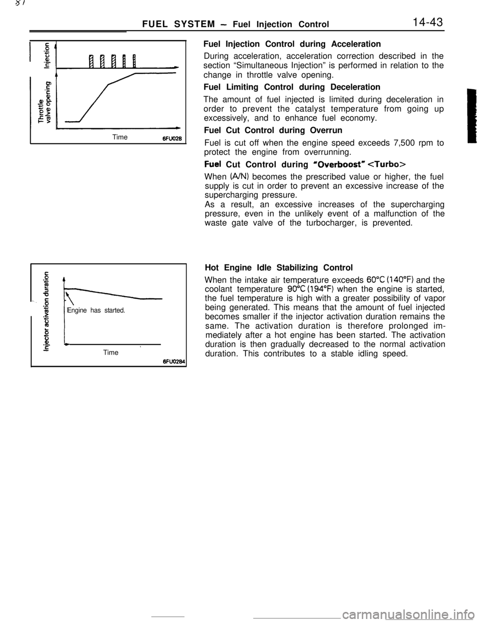
El.-*STime ’6fFuel Injection Control during Acceleration
During acceleration, acceleration correction described in the
section “Simultaneous Injection” is performed in relation to the
change in throttle valve opening.
Fuel Limiting Control during Deceleration
The amount of fuel injected is limited during deceleration in
order to prevent the catalyst temperature from going up
excessively, and to enhance fuel economy.
Fuel Cut Control during Overrun
Fuel is cut off when the engine speed exceeds 7,500 rpm to
protect the engine from overrunning.
Fuel Cut Control during ‘Overboost”
(A/N) becomes the prescribed value or higher, the fuel
supply is cut in order to prevent an excessive increase of the
supercharging pressure.
As a result, an excessive increases of the supercharging
pressure, even in the unlikely event of a malfunction of the
waste gate valve of the turbocharger, is prevented.
Hot Engine Idle Stabilizing Control
When the intake air temperature exceeds
60°C (140°F) and the
coolant temperature
90°C (194°F) when the engine is started,
the fuel temperature is high with a greater possibility of vapor
being generated. This means that the amount of fuel injected
becomes smaller if the injector activation duration remains the
same. The activation duration is therefore prolonged im-
mediately after a hot engine has been started. The activation
duration is then gradually decreased to the normal activation
duration. This contributes to a stable idling speed.
Page 161 of 391
FUEL SYSTEM -Idle Speed Control14-49
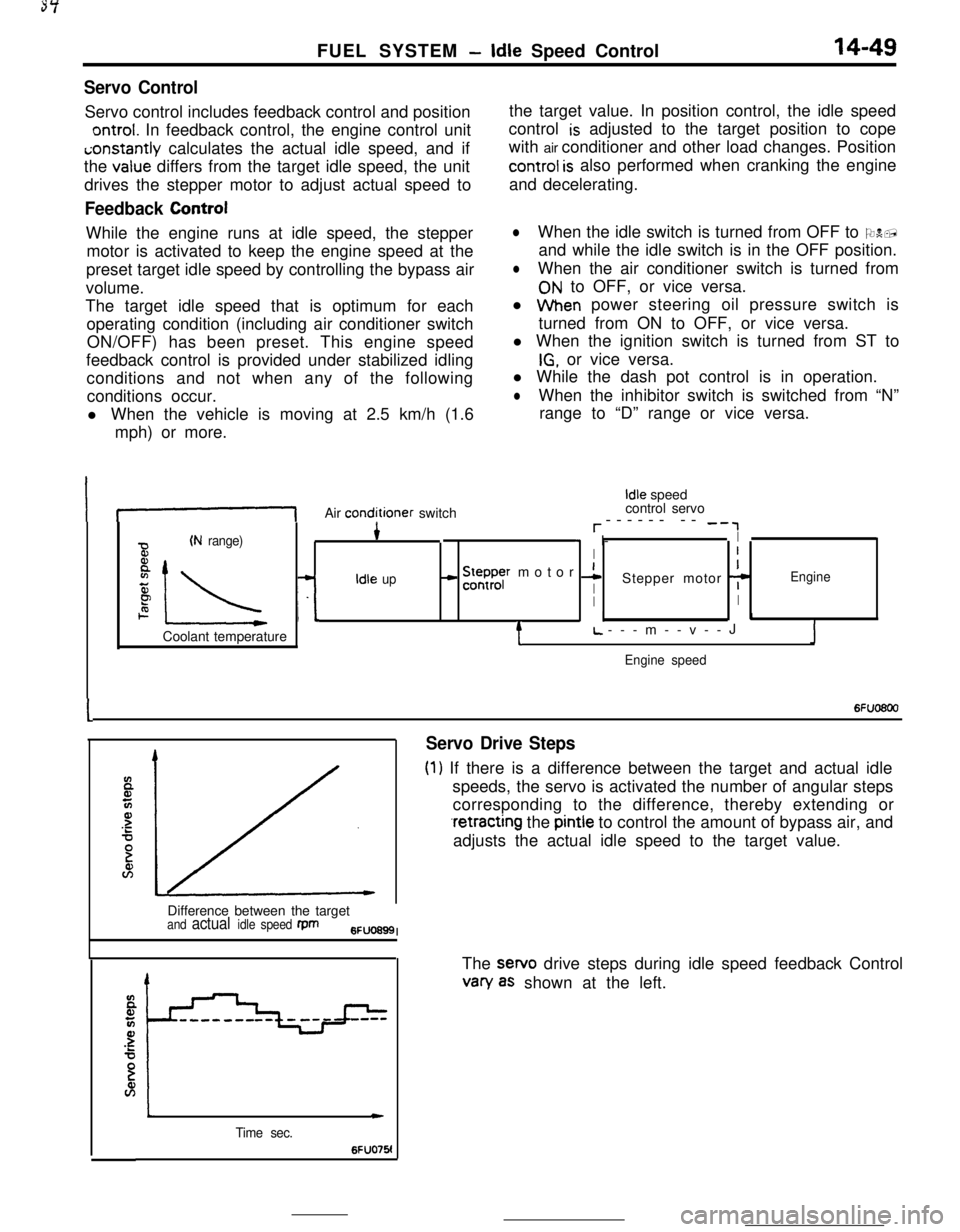
Servo ControlServo control includes feedback control and position
ontrol. In feedback control, the engine control uniti;onstantly calculates the actual idle speed, and if
the
value differs from the target idle speed, the unit
drives the stepper motor to adjust actual speed to
Feedback ControlWhile the engine runs at idle speed, the stepper
motor is activated to keep the engine speed at the
preset target idle speed by controlling the bypass air
volume.
The target idle speed that is optimum for each
operating condition (including air conditioner switch
ON/OFF) has been preset. This engine speed
feedback control is provided under stabilized idling
conditions and not when any of the following
conditions occur.
l When the vehicle is moving at 2.5 km/h (1.6
mph) or more.the target value. In position control, the idle speed
control
is adjusted to the target position to cope
with air conditioner and other load changes. Position
control is also performed when cranking the engine
and decelerating.
lWhen the idle switch is turned from OFF to ON,
and while the idle switch is in the OFF position.
lWhen the air conditioner switch is turned from
ON to OFF, or vice versa.
l When power steering oil pressure switch is
turned from ON to OFF, or vice versa.
l When the ignition switch is turned from ST to
IG, or vice versa.
l While the dash pot control is in operation.
lWhen the inhibitor switch is switched from “N”
range to “D” range or vice versa.
If-1Air conditioner switch
Idle speed
control servo
r------ -- -‘,
(N range)4* I-I
BI
8
IL -L
- !5ysr motor 1I
zIdle upIStepper motor 7Engine
PII2. I.1Coolant temperature
tL.---m--v--JJ
Engine speed
I6Fuo6oo
Servo Drive Steps
(1) If there is a difference between the target and actual idle
speeds, the servo is activated the number of angular steps
corresponding to the difference, thereby extending or
.retracting the pintle to control the amount of bypass air, and
adjusts the actual idle speed to the target value.
Difference between the target
and actual idle speed fpm6FUO699I
Time sec.
c
6FUO76!The sewo drive steps during idle speed feedback Control
van/ as shown at the left.
Page 162 of 391
14-50FUEL SYSTEM- Idle Speed Control
SDeed adiustina screwI -Throttle valve
Lw-3O(-22) 0132) 30(86! 601140) 9ofl94)Coolant temperature
“C (OF)6FUO641
E94
72--2--I
Q--.-.-z
3201.000 --4-\-\
5P9.o%IIIaI L-2O(-41 Of3214Of104)801176)Coolant temperature
“C VF)6FU028E
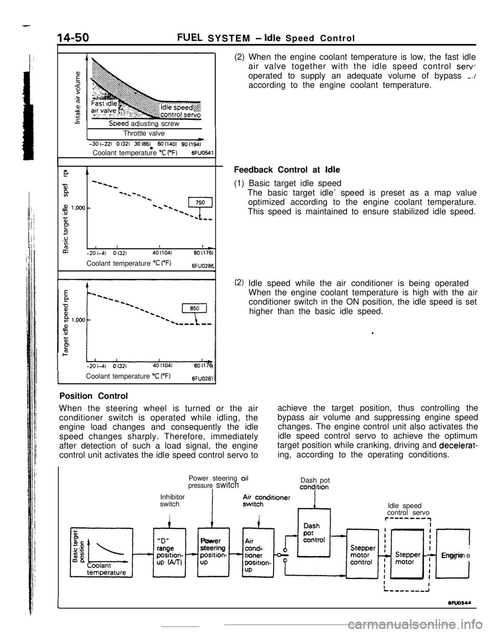
-201-4) Of3214OI104180(176(2) When the engine coolant temperature is low, the fast idle
air valve together with the idle speed control
servoperated to supply an adequate volume of bypass
,.raccording to the engine coolant temperature.
Feedback Control at
Idle(1) Basic target idle speed
The basic target idle’ speed is preset as a map value
optimized according to the engine coolant temperature.
This speed is maintained to ensure stabilized idle speed.
(2) Idle speed while the air conditioner is being operated
When the engine coolant temperature is high with the air
conditioner switch in the ON position, the idle speed is set
higher than the basic idle speed.
,
ICoolant temperature “C VF)6FUO28:Position Control
When the steering wheel is turned or the air
conditioner switch is operated while idling, theachieve the target position, thus controlling the
engine load changes and consequently the idlebypass air volume and suppressing engine speed
changes. The engine control unit also activates the
speed changes sharply. Therefore, immediately
after detection of such a load signal, the engine
control unit activates the idle speed control servo toidle speed control servo to achieve the optimum
target position while cranking, driving and decelerat-
ing, according to the operating conditions.
Power steering oil
pressure switchIInhibitor
switch
IDash pot
concjition“D”
xl
rangeposition-
UP W-U
IAlPower
steeringposition-
UP.4~i~hnditioner
IIdle speed
control servor”--““IiiI
I
c
IEngine
I
I
1wuosu
-
Page 163 of 391
FUEL SYSTEM -Idle Speed Control14-51
_ 0 (32)80 (175)Coolant temperature “C (“F)6FUO2653
ATarget position during operation
of the power steering systemIDLE CONTROL SERVO POSITION CONTROL WHEN THE
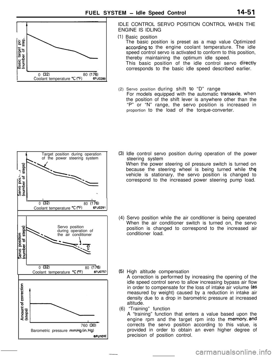
ENGINE IS IDLING
(1) Basic position
The basic position is preset as a map value Optimized
according to the engine coolant temperature. The idle
speed control servo is activated to conform to this position,
thereby maintaining the optimum idle speed.
This basic position of the idle control servo
diiectlycorresponds to the basic idle speed described earlier.
1II
0(32)
80(176)Coolant temperature
“C VW6FUO291Servo position
during operation of
the air conditioner
0(32)
80(176)Coolant temperature “C (“F)6FUO757
1L)760 (30)Barometric pressure mmHg
(in.Hg)BFUlOlC(2) Servo position during shift to “D” range
For models equipped with the automatic
transaxle.when
the position of the shift lever is anywhere other than the
“P” or “N” range, the servo position is increased in
proportion to the load of the torque-converter.
(3) Idle control servo position during operation of the power
steering system
When the power steering oil pressure switch is turned on
because the steering wheel is being turned while
thevehicle is stationary, the servo position is changed to
correspond to the increased power steering pump load.
(4) Servo position while the air conditioner is being operated
When the air conditioner switch is turned on, the servo
position is changed to correspond to the increased air
conditioner load.
(5) High altitude compensation
A correction is performed by increasing the opening of the
idle speed control servo to allow increasing bypass air flow
in order to compensate for the loss of intake air volume
(asmeasured by weight) caused by a reduction in intake air
density due to a drop in barometric pressure at increased
altitude.
(6) “Training” function
A “training” function that enters a value based upon the
engine rpm and the target rpm into the memon/,
andcorrects the servo position according to this value, is
provided in order to obtain an even higher degree of
precision of position control.
Page 164 of 391
--
14-52FUEL SYSTEM - Idle Speed Control
4
Start of deceleration
DLhq ON
position
I*2 to 6
Time sec.6FUO295
II)
0(32180(176)Temperature “C 1°F)6FUO29t
CONTROL WHEN THE ENGINE SPEED IS UNUSUALLY LOWThe followi
gcontrols are provided when the engine speecfalls below
i5;D rpm after the engine has been fully warmed-up
[with engine coolant temperature more than
55°C (131”F)].
(1) During feedback control
The idle speed control servo is activated immediately by a
particular number of angular steps which represent the
feedback correction.
(2) During servo position control
The idle speed control servo is activated to conform to
aposition corresponding to an increased number of steps
(46
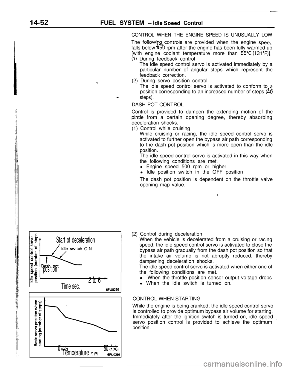
steps).DASH POT CONTROL
Control is provided to dampen the extending motion of the
pintle from a certain opening degree, thereby absorbing
deceleration shocks.
(1) Control while cruising
While cruising or racing, the idle speed control servo is
activated to further open the bypass air path corresponding
to the dash pot position which is more open than the idle
position.The idle speed control servo is activated in this way when
the following conditions are met.
l Engine speed 500 rpm or higher
l Idle position switch in the OFF position
The dash pot position is dependent on the throttle valve
opening map value.,
(2) Control during deceleration
When the vehicle is decelerated from a cruising or racing
speed, the idle speed control servo is activated to close the
bypass air path gradually from the dash pot position so that
the intake air volume is not abruptly reduced, thereby
dampening deceleration shocks.
The idle speed control servo is activated when either one of
the following conditions are met.
lWhen the throttle position sensor output voltage drops
l When the idle switch is turned on.
CONTROL WHEN STARTING
While the engine is being cranked, the idle speed control servo
is controlled to provide optimum bypass air volume for starting.
Immediately after the ignition switch is turned on, idle speed
servo position control is provided to achieve the optimum
_
position.
Page 165 of 391
FUEL SYSTEM -Idle Speed Control I Power Supply Control14-53
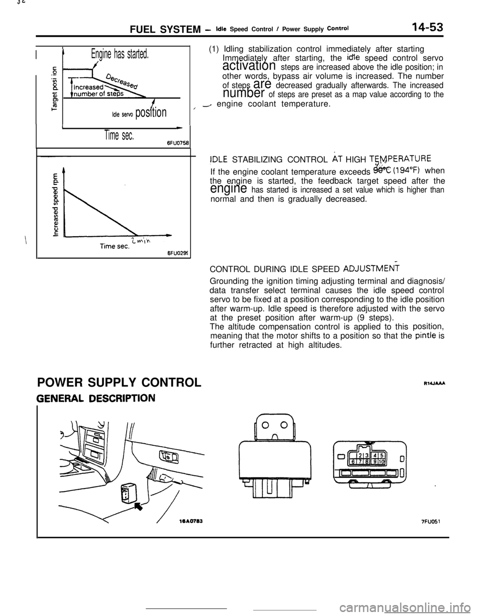
IIEngine has started.(1) Idling stabilization control immediately after starting
Immediately after starting, the idle speed control servo
sactivation steps are increased above the idle position; in.-
‘Bother words, bypass air volume is increased. The numberof steps are decreased gradually afterwards. The increased
55number of steps are preset as a map value according to theP2f/-/ engine coolant temperature.
Idle servo position
I
Time sec.
c
6FUO756
6FUO29z
!DLE STABILIZING CONTROL AT HIGH TERPERATURE
If the engine coolant temperature exceeds
&k (194°F) when
the engine is started, the feedback target speed after the
engine has started is increased a set value which is higher thannormal and then is gradually decreased.
CONTROL DURING IDLE SPEED ADJUSTMEN?
Grounding the ignition timing adjusting terminal and diagnosis/
data transfer select terminal causes the idle speed control
servo to be fixed at a position corresponding to the idle position
after warm-up. Idle speed is therefore adjusted with the servo
at the preset position after warm-up (9 steps).
The altitude compensation control is applied to thisposition,
meaning that the motor shifts to a position so that the pintle is
further retracted at high altitudes.
POWER SUPPLY CONTROL
GENERAL DESCRIPTION
RlUAAA
7FUO51
Page 167 of 391
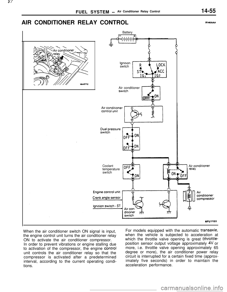
FUEL SYSTEM -Air Conditioner Relay Control14-55AIR CONDITIONER RELAY CONTROL
Batterylgnltlon
switch
Air conditionerswitch
@OFF ON
Coolanttemperature
switch
RlUCAAA
/Air condittoner
When the air conditioner switch ON signal is input,
the engine control unit turns the air conditioner relay
ON to activate the air conditioner compressor.
In order to prevent vibrations or engine stalling due
to activation of the compressor, the engine control
unit controls the air conditioner relay so that the
compressor is activated after a predetermined
interval, according to the current operating condi-
tions.For models equipped with the automatic
transaxle,when the vehicle is subjected to acceleration at
which the throttle valve opening is great (throttle-
position sensor output voltage approximately
4V or
more, i.e. throttle valve opening approximately 65
degree or more), the air conditioner power relay
circuit is interrupted for a certain fixed time (approx-
imately five seconds) in order to maintain the
acceleration performance.
Page 371 of 391
-.-- ----_-
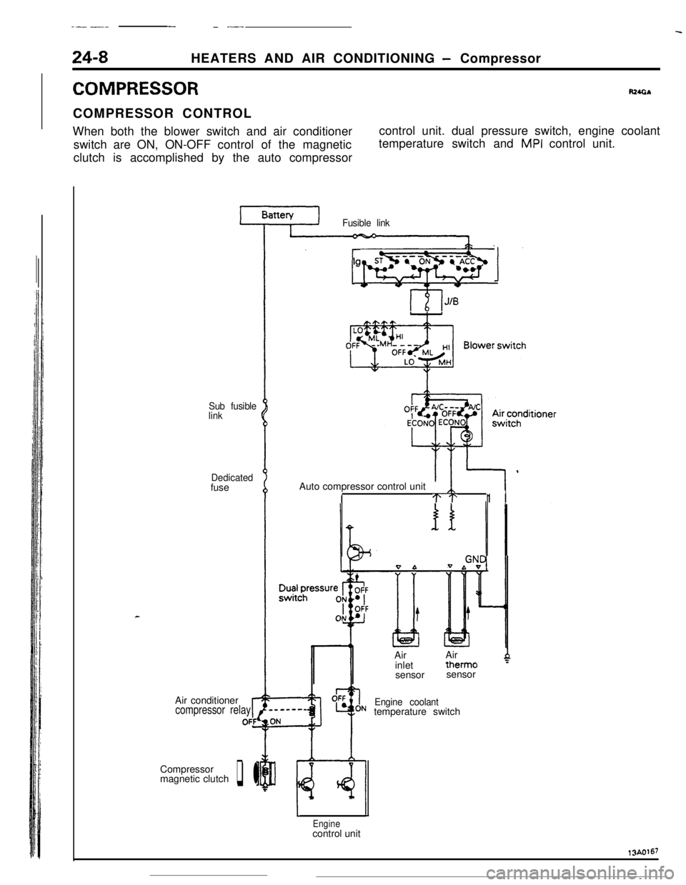
24-8HEATERS AND AIR CONDITIONING - Compressor
COMPRESSORR24GbCOMPRESSOR CONTROL
When both the blower switch and air conditioner
switch are ON, ON-OFF control of the magnetic
clutch is accomplished by the auto compressorcontrol unit. dual pressure switch, engine coolant
temperature switch and
MPI control unit.
Sub fusible
link
Dedicatedfuse
Air conditioner
compressor relayrOFfCompressor
magnetic clutch
q l
Fusible link
lgnitionsyhWqb 1Auto compressor control unit
ITT1 I
0 bIAirAir
inlettherm0
4sensorsensor
Engine coolanttemperature switch
Enginecontrol unit13A0167