tow MITSUBISHI ECLIPSE 1990 Owner's Guide
[x] Cancel search | Manufacturer: MITSUBISHI, Model Year: 1990, Model line: ECLIPSE, Model: MITSUBISHI ECLIPSE 1990Pages: 391, PDF Size: 15.27 MB
Page 348 of 391

BODY - Seat Belts
._-- -
23-31
Shoulder beltI
Lapbelt
IGlove box pad toasty
Knee protector
Guide rail\Fasten switch
\
SEAT BELTSRZ3SBAS
On Federal and California vehicles automatic seat belts (Manualseat belts on vehicles for Canada) are installed on the front
seats and the
3-point seat belts with ELR on the rear seat, both
contributing to the enhanced safety and ease of use.
AUTOMATIC SEAT BELTS
GENERAL INFORMATION
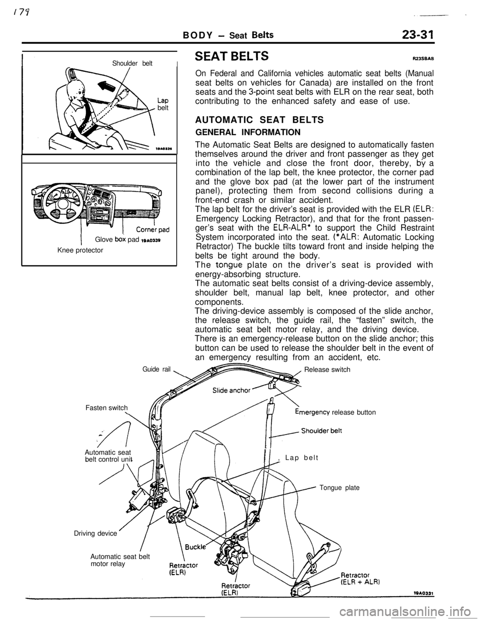
The Automatic Seat Belts are designed to automatically fasten
themselves around the driver and front passenger as they get
into the vehicle and close the front door, thereby,
by a
combination of the lap belt, the knee protector, the corner pad
and the glove box pad (at the lower part of the instrument
panel), protecting them from second collisions during a
front-end crash or similar accident.
The lap belt for the driver’s seat is provided with the ELR
(ELR:Emergency Locking Retractor), and that for the front passen-
ger’s seat with the
ELR-ALR” to support the Child Restraint
System incorporated into the seat. (“ALR: Automatic Locking
Retractor) The buckle tilts toward front and inside helping the
belts be tight around the body.
The
tongue plate on the driver’s seat is provided with
energy-absorbing structure.
The automatic seat belts consist of a driving-device assembly,
shoulder belt, manual lap belt, knee protector, and other
components.
The driving-device assembly is composed of the slide anchor,
the release switch, the guide rail, the “fasten” switch, the
automatic seat belt motor relay, and the driving device.
There is an emergency-release button on the slide anchor; this
button can be used to release the shoulder belt in the event of
an emergency resulting from an accident, etc.
Release switchmergency
release button
Automatic seat
belt control unit
PI, Lap belt
Tongue plateDriving device
Automatic seat belt
motor relay
Page 352 of 391

BODY - Seat Belts23-35OPERATlON OF DRIVING DEVICE
TapeDrive spring
Izz;b3;:,e
tape is
Projectionof drum BDrum B/
When the tape is
wound outMotor
\ /Gear ADrum springi9w2a9When the
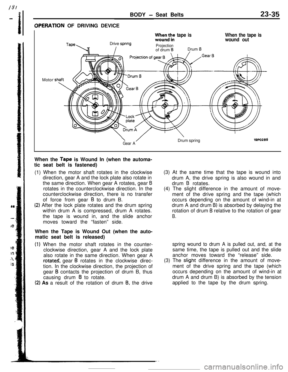
Tape is Wound In (when the automa-
tic seat belt is fastened)
(1) When the motor shaft rotates in the clockwise
direction, gear A and the lock plate also rotate in
the same direction. When gear A rotates, gear
Brotates in the counterclockwise direction. In the
counterclockwise direction, there is no transfer
of force from gear
B to drum B.
(2) After the lock plate rotates and the drum spring
within drum A is compressed, drum A rotates.
the tape is wound in, and the slide anchor
moves toward the “fasten” side.
When the Tape is Wound Out (when the auto-
matic seat belt is released)
(1) When the motor shaft rotates in the counter-
clockwise direction, gear A and the lock plate
also rotate in the same direction. When gear A
rotate.S, gear B rotates in the clockwise direc-
tion. In the clockwise direction, the projection of
gear
B contacts the projection of drum B, thus
causing drum
B to rotate.
(2) As a result of the rotation of drum 8, the drive(3) At the same time that the tape is wound into
drum A, the drive spring is also wound in and
drum
B rotates.
(4) The slight difference in the amount of move-
ment of the drive spring and the tape (which
occurs depending on the amount of wind-in at
drum A and drum
B) is absorbed by delaying the
rotation of drum
B relative to the rotation of gear
B.
spring wound to drum A is pulled out, and, at thesame time, the tape is pulled out and the slide
anchor moves toward the “release” side.
(3) The slight difference in the amount of move-
ment of the drive spring and the tape (which
occurs depending on the amount of wind-in at
drum A and drum B) is absorbed by the tension
applied to the tape by the drum spring.
Page 357 of 391

23-40BODY - Seat Belts
Door latch
switch
Ignition
switch
(LOCK or
ZjTI
Warninglight
.
F-w4Approx. 6 sec.
~1: Warning alarm when ignition
switch is activated.
r2: Approx. 0.7 sec./cycle
Driver’s side
latch switch
Ignition
switch
(LOCK or
Er:rI
ti Fasten” switch
Driver’s side
(ON) i;outer switch
(OFF)I!
’ III
Buzzer(ON’
(OFF)c
Warning ’light
kprox. 66 sec.’Ignition
switch
(LOCK or zm
zs;;;$s (ON)
side outer
switch(OFFIr
Warninglight
Apprbx.ti sec.Warning Alarm when the Automatic Seat Belt is
no*Completely Fastened (when the slide anchor, during
movement, stops before completion of travel, or when it
moves toward the “fasten” side)
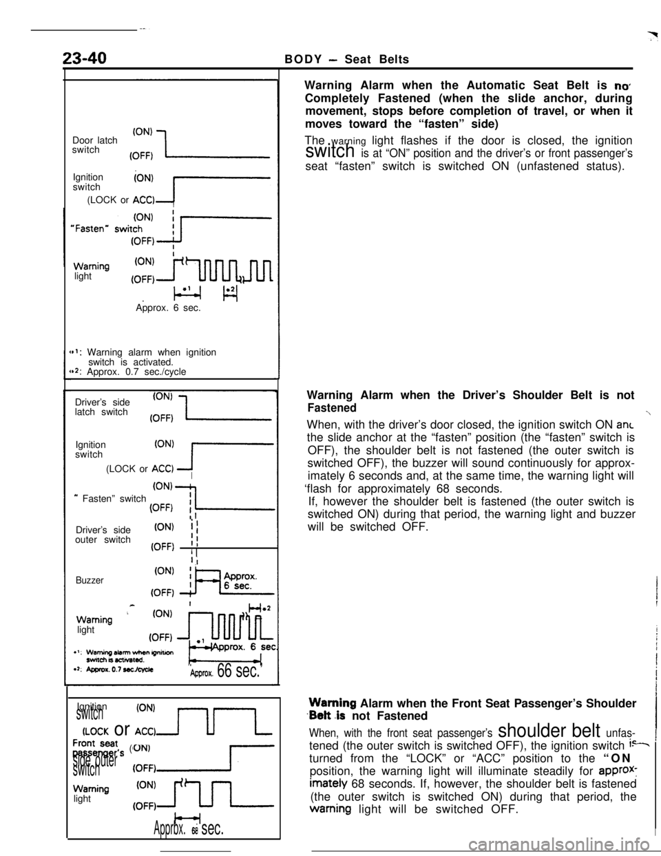
The warning light flashes if the door is closed, the ignition
switch is at “ON” position and the driver’s or front passenger’sseat “fasten” switch is switched ON (unfastened status).
Warning Alarm when the Driver’s Shoulder Belt is not
FastenedWhen, with the driver’s door closed, the ignition switch ON ant
the slide anchor at the “fasten” position (the “fasten” switch is
OFF), the shoulder belt is not fastened (the outer switch is
switched OFF), the buzzer will sound continuously for approx-
imately 6 seconds and, at the same time, the warning light will
‘flash for approximately 68 seconds.
If, however the shoulder belt is fastened (the outer switch is
switched ON) during that period, the warning light and buzzer
will be switched OFF.Warning Alarm when the Front Seat Passenger’s Shoulder
.Belt .is not Fastened
When, with the front seat passenger’s shoulder belt unfas-tened (the outer switch is switched OFF), the ignition switch
i--turned from the “LOCK” or “ACC” position to the “ON
position, the warning light will illuminate steadily for
approx-imately 68 seconds. If, however, the shoulder belt is fastened
(the outer switch is switched ON) during that period, thewarning light will be switched OFF.
I
Page 358 of 391

BODY- Seat Belts*23-41
switchDriver’s
side buckle
switch
Buzzer(ON’ XL(OFF)
,: Approx. 0.7 sec./cycle
Key-reminder (ON)switch (A) (OFF)
Buzzer
19Poo270
Automatic seat belt control unit
connector terminals
lsPo2eeWarning Alarm when the Driver’s Lap Belt is not Fastened
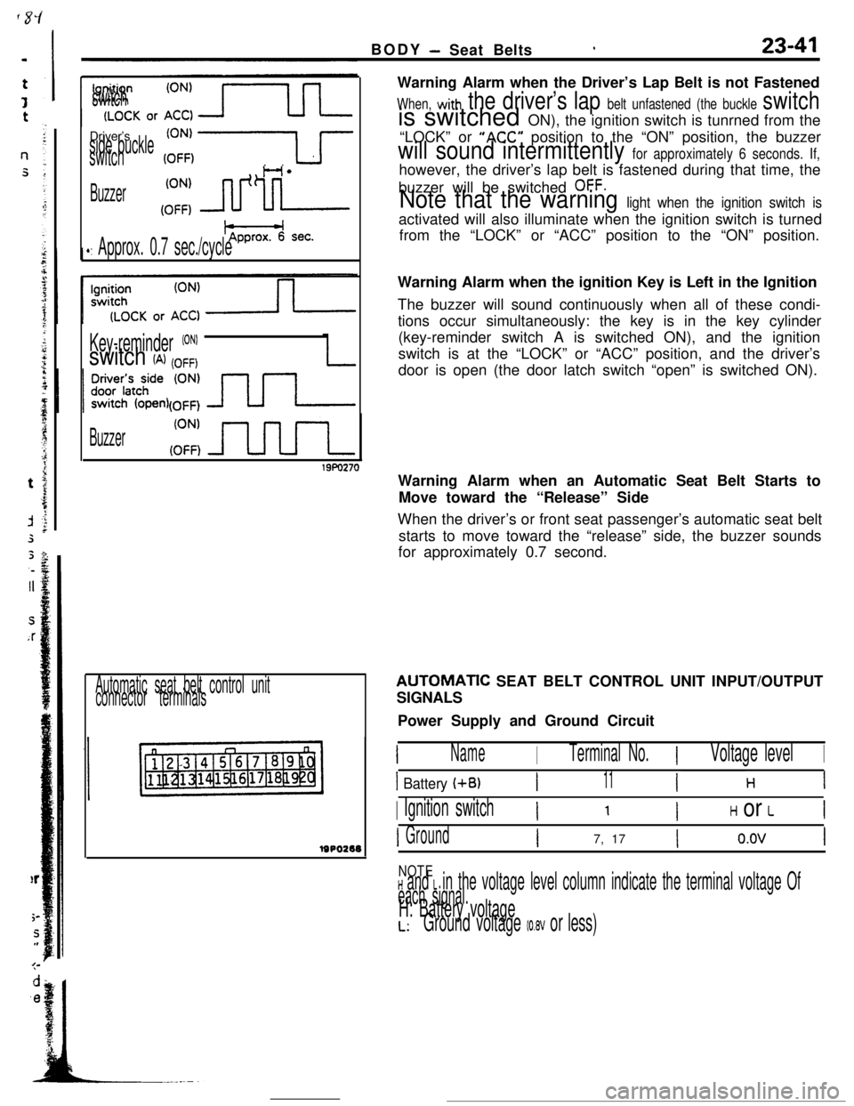
When, with the driver’s lap belt unfastened (the buckle switchis switched ON), the ignition switch is tunrned from the
“LOCK” or
“ACC” position to the “ON” position, the buzzer
will sound intermittently for approximately 6 seconds. If,however, the driver’s lap belt is fastened during that time, the
buzzer will be switched
OFF.
Note that the warning light when the ignition switch isactivated will also illuminate when the ignition switch is turned
from the “LOCK” or “ACC” position to the “ON” position.
Warning Alarm when the ignition Key is Left in the Ignition
The buzzer will sound continuously when all of these condi-
tions occur simultaneously: the key is in the key cylinder
(key-reminder switch A is switched ON), and the ignition
switch is at the “LOCK” or “ACC” position, and the driver’s
door is open (the door latch switch “open” is switched ON).
Warning Alarm when an Automatic Seat Belt Starts to
Move toward the “Release” Side
When the driver’s or front seat passenger’s automatic seat belt
starts to move toward the “release” side, the buzzer sounds
for approximately 0.7 second.AUTOMATlC SEAT BELT CONTROL UNIT INPUT/OUTPUT
SIGNALS
Power Supply and Ground Circuit
INameITerminal No.IVoltage levelI
I Battery (+B)I11I H 1
I Ignition switchI ’ IH or LI
IGroundI7, 17Io.ovI
NOTEH and L in the voltage level column indicate the terminal voltage Of
each signal.H: Battery voltageL:Ground voltage (0.8V or less)
Page 370 of 391

HEATERS AND AIR CONDITIONING - Heater Construction24-7
IKnob posltionDamper position and air flow direction
Air outflow locations
Outside air
Recircu-lation air
2010246
Recircu-iation airDEF
2OAO247Temperature Control Knob
IKnob positionDamper position and air ‘flow directionOperation
When the temperature control knob or
the heater control is rotated fully
counterclockwise toward the cool air
position, the upper side of the heater
core will be blocked up by the blend
air damper A. whereas the lower side
of the heater core
will be blocked up by
the blend air damper 8. As a result.
all the air from the blower motor does
not pass through the heater core but
directly flows out as cool air.
Blend air damper CBlend air damper A
x!= cY?l-nY-/
-1 From
To air Voutflowopenings*blower
motor
Hester ‘OreOUO,,O
Blend air damper CBlend air damper A,//7When the temperature control knob of
the heater control is rotated fully
ctockwise toward the warm air position.the blend air dampers A and Bwill block the cool air paths.
The cool air from the blower motor
passes through the heater core for
maximum heating..
Tooutflow
openings
Blend al’r damper B
When the temperature control knob of
the heater control is rotated to the
mid position, the blend air dampers A
and B will split the air stream intotwo branches, one passing through the
heater core and one not passing through
the heater core. The blend damper air
Cintroduces cool air from the heater core
top into the heater unit chamber. Air
conditioning is provided by mixing this
cool air with hot air heated by the
heater cores.
Blend air damper CBlend/ air damper AL
2OAO391Blend air damoer B
--.-__.__ ,_ .