lock MITSUBISHI ECLIPSE 1990 Repair Manual
[x] Cancel search | Manufacturer: MITSUBISHI, Model Year: 1990, Model line: ECLIPSE, Model: MITSUBISHI ECLIPSE 1990Pages: 391, PDF Size: 15.27 MB
Page 357 of 391

23-40BODY - Seat Belts
Door latch
switch
Ignition
switch
(LOCK or
ZjTI
Warninglight
.
F-w4Approx. 6 sec.
~1: Warning alarm when ignition
switch is activated.
r2: Approx. 0.7 sec./cycle
Driver’s side
latch switch
Ignition
switch
(LOCK or
Er:rI
ti Fasten” switch
Driver’s side
(ON) i;outer switch
(OFF)I!
’ III
Buzzer(ON’
(OFF)c
Warning ’light
kprox. 66 sec.’Ignition
switch
(LOCK or zm
zs;;;$s (ON)
side outer
switch(OFFIr
Warninglight
Apprbx.ti sec.Warning Alarm when the Automatic Seat Belt is
no*Completely Fastened (when the slide anchor, during
movement, stops before completion of travel, or when it
moves toward the “fasten” side)
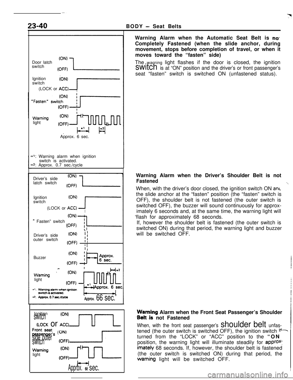
The warning light flashes if the door is closed, the ignition
switch is at “ON” position and the driver’s or front passenger’sseat “fasten” switch is switched ON (unfastened status).
Warning Alarm when the Driver’s Shoulder Belt is not
FastenedWhen, with the driver’s door closed, the ignition switch ON ant
the slide anchor at the “fasten” position (the “fasten” switch is
OFF), the shoulder belt is not fastened (the outer switch is
switched OFF), the buzzer will sound continuously for approx-
imately 6 seconds and, at the same time, the warning light will
‘flash for approximately 68 seconds.
If, however the shoulder belt is fastened (the outer switch is
switched ON) during that period, the warning light and buzzer
will be switched OFF.Warning Alarm when the Front Seat Passenger’s Shoulder
.Belt .is not Fastened
When, with the front seat passenger’s shoulder belt unfas-tened (the outer switch is switched OFF), the ignition switch
i--turned from the “LOCK” or “ACC” position to the “ON
position, the warning light will illuminate steadily for
approx-imately 68 seconds. If, however, the shoulder belt is fastened
(the outer switch is switched ON) during that period, thewarning light will be switched OFF.
I
Page 358 of 391

BODY- Seat Belts*23-41
switchDriver’s
side buckle
switch
Buzzer(ON’ XL(OFF)
,: Approx. 0.7 sec./cycle
Key-reminder (ON)switch (A) (OFF)
Buzzer
19Poo270
Automatic seat belt control unit
connector terminals
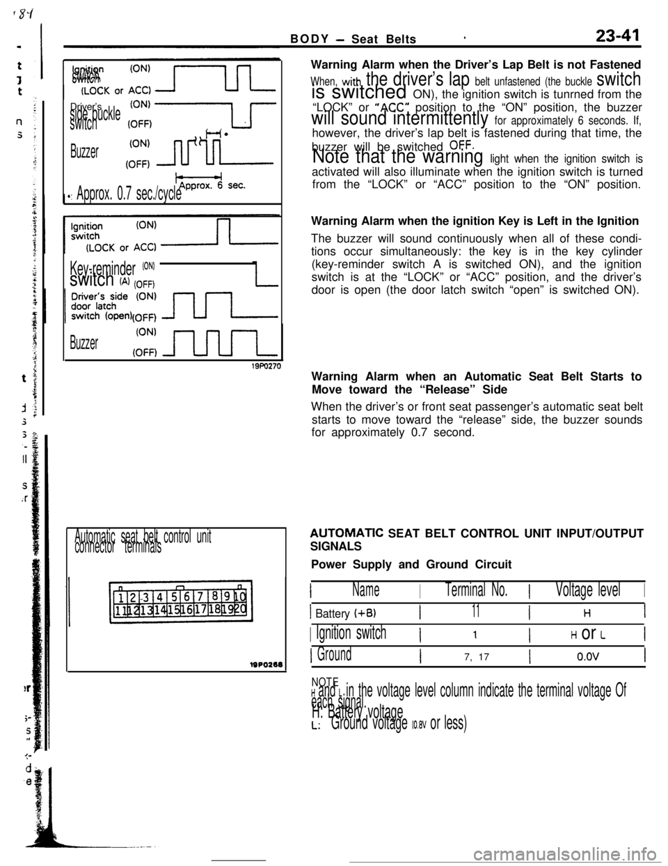
lsPo2eeWarning Alarm when the Driver’s Lap Belt is not Fastened
When, with the driver’s lap belt unfastened (the buckle switchis switched ON), the ignition switch is tunrned from the
“LOCK” or
“ACC” position to the “ON” position, the buzzer
will sound intermittently for approximately 6 seconds. If,however, the driver’s lap belt is fastened during that time, the
buzzer will be switched
OFF.
Note that the warning light when the ignition switch isactivated will also illuminate when the ignition switch is turned
from the “LOCK” or “ACC” position to the “ON” position.
Warning Alarm when the ignition Key is Left in the Ignition
The buzzer will sound continuously when all of these condi-
tions occur simultaneously: the key is in the key cylinder
(key-reminder switch A is switched ON), and the ignition
switch is at the “LOCK” or “ACC” position, and the driver’s
door is open (the door latch switch “open” is switched ON).
Warning Alarm when an Automatic Seat Belt Starts to
Move toward the “Release” Side
When the driver’s or front seat passenger’s automatic seat belt
starts to move toward the “release” side, the buzzer sounds
for approximately 0.7 second.AUTOMATlC SEAT BELT CONTROL UNIT INPUT/OUTPUT
SIGNALS
Power Supply and Ground Circuit
INameITerminal No.IVoltage levelI
I Battery (+B)I11I H 1
I Ignition switchI ’ IH or LI
IGroundI7, 17Io.ovI
NOTEH and L in the voltage level column indicate the terminal voltage Of
each signal.H: Battery voltageL:Ground voltage (0.8V or less)
Page 359 of 391

23-42BODY - Seat Belts
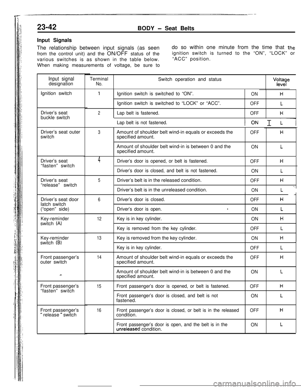
Input Signals
The relationship between input signals (as seen
from the control unit) and the ON/OFF status of the
various switches is as shown in the table below.
When making measurements of voltage, be sure todo so within one minute from the time that
theignition switch is turned to the “ON”, “LOCK” or
“ACC” position.
Input signaldesignation
Ignition switch
Driver’s seat
buckle switch
Driver’s seat outer
3switchAmount of shoulder belt wind-in equals or exceeds theOFFHspecified amount.
Driver’s seat
“fasten” switch
Driver’s seat
“release” switch
Driver’s seat door
latch switch
(“open” side)
Key-reminderswitch
(A)
Key-reminderswitch (B)Front passenger’s
outer switch
cFront passenger’s
“fasten” switch
Front passenger’s
a release m switch
Terminal
No.Switch operation and statusVcv;y
1Ignition switch is switched to “ON”.ONHIgnition switch is switched to “LOCK” or “ACC”.
OFFL
2
Lap belt is fastened.OFFH
Lap belt is not fastened.ION I ilAmount of shoulder belt wind-in is between 0 and the
specified amount.
ONL
4Driver’s door is opened, or belt is fastened.OFFH
Driver’s door is closed, and belt is not fastened.
ONL
5Driver’s belt is in the released condition.
OFFHDriver’s belt is in the unreleased condition.
ONL Y
6
12
13
14
15Driver’s door is closed.
Driver’s door is open.
+
Key is in key cylinder.
Key is removed from the key cylinder.Key is removed from the key cylinder.
Key is in key cylinder.Amount of shoulder belt wind-in equals or exceeds the
specified amount.
Amount of shoulder belt wind-in is between 0 and the
specified amount.
Front passenger’s door is opened, or belt is fastened.
Front passenger’s door is closed, and belt is notfastened.
OFFH I
ONL
ONH
OFFL
ONH
OFFL
OFFH
ONL
OFFH
ONL
16Front passenger’s door is closed, or belt is in the releasedOFFHcondition.
Front passenger’s door is open, and the belt is in theunreleased condition.ONL
,
Page 370 of 391

HEATERS AND AIR CONDITIONING - Heater Construction24-7
IKnob posltionDamper position and air flow direction
Air outflow locations
Outside air
Recircu-lation air
2010246
Recircu-iation airDEF
2OAO247Temperature Control Knob
IKnob positionDamper position and air ‘flow directionOperation
When the temperature control knob or
the heater control is rotated fully
counterclockwise toward the cool air
position, the upper side of the heater
core will be blocked up by the blend
air damper A. whereas the lower side
of the heater core
will be blocked up by
the blend air damper 8. As a result.
all the air from the blower motor does
not pass through the heater core but
directly flows out as cool air.
Blend air damper CBlend air damper A
x!= cY?l-nY-/
-1 From
To air Voutflowopenings*blower
motor
Hester ‘OreOUO,,O
Blend air damper CBlend air damper A,//7When the temperature control knob of
the heater control is rotated fully
ctockwise toward the warm air position.the blend air dampers A and Bwill block the cool air paths.
The cool air from the blower motor
passes through the heater core for
maximum heating..
Tooutflow
openings
Blend al’r damper B
When the temperature control knob of
the heater control is rotated to the
mid position, the blend air dampers A
and B will split the air stream intotwo branches, one passing through the
heater core and one not passing through
the heater core. The blend damper air
Cintroduces cool air from the heater core
top into the heater unit chamber. Air
conditioning is provided by mixing this
cool air with hot air heated by the
heater cores.
Blend air damper CBlend/ air damper AL
2OAO391Blend air damoer B
--.-__.__ ,_ .