lock MITSUBISHI ECLIPSE 1990 Workshop Manual
[x] Cancel search | Manufacturer: MITSUBISHI, Model Year: 1990, Model line: ECLIPSE, Model: MITSUBISHI ECLIPSE 1990Pages: 391, PDF Size: 15.27 MB
Page 252 of 391
.-
I
21-28AUTOMATIC TRANSAXLE - Transaxle Mechanism
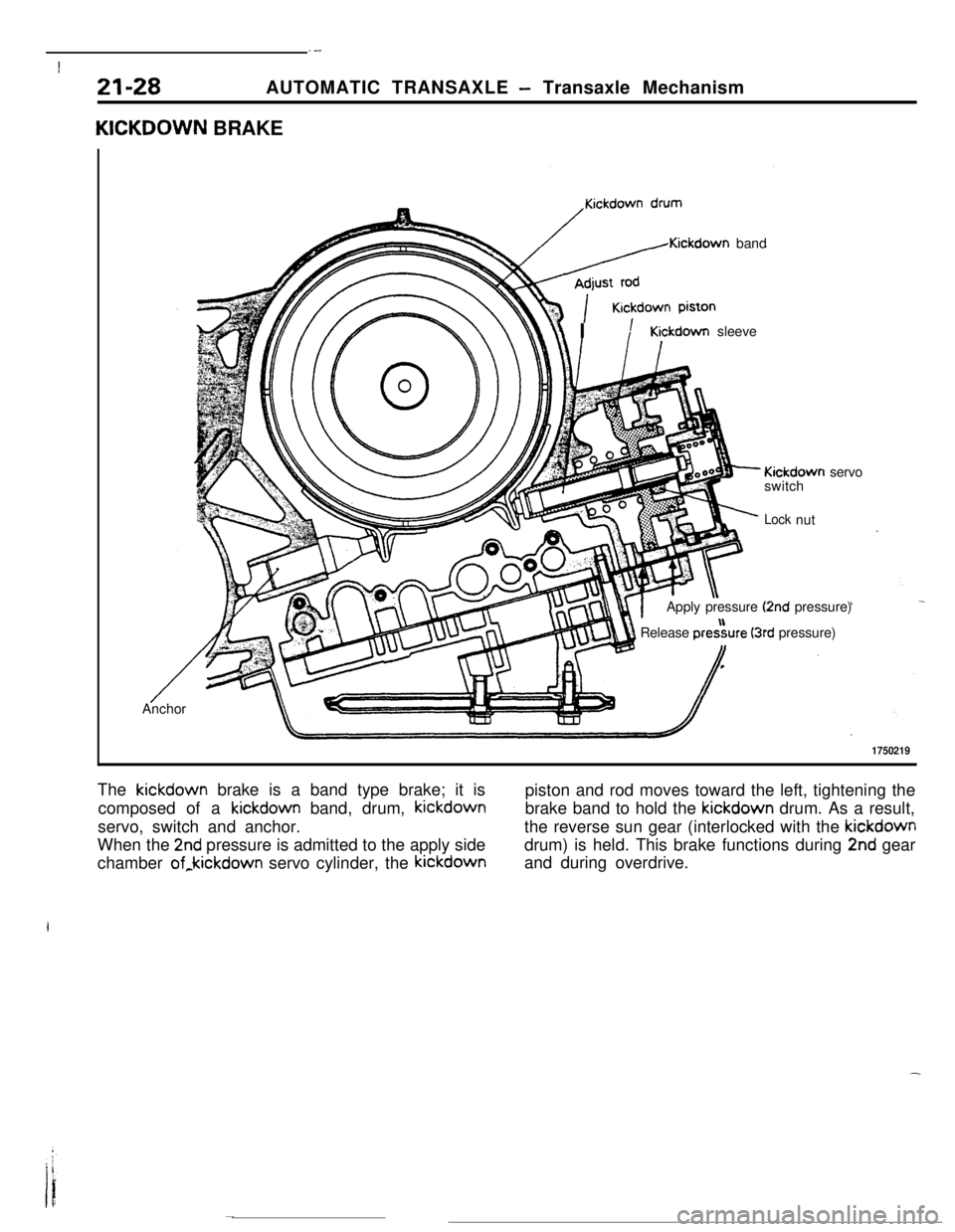
KICKDOWN BRAKE
/Kickdown band
r\\ IKickdown sleeve
- Kickdown servo
switch
;‘- Locknut
Apply pressure
(2nd pressure)
1 Release pre&re (3rd pressure)I,
/ --Anchor
1750219The kickdown brake is a band type brake; it is
piston and rod moves toward the left, tightening the
composed of a kickdown band, drum, kickdownbrake band to hold the kickdown drum. As a result,
servo, switch and anchor.the reverse sun gear (interlocked with the kickdown
When the
2nd pressure is admitted to the apply sidedrum) is held. This brake functions during 2nd gear
chamber of,kickdown servo cylinder, the kickdownand during overdrive.
Page 255 of 391
iAUTOMATIC TRANSAXLE
- Transaxle Mechanism
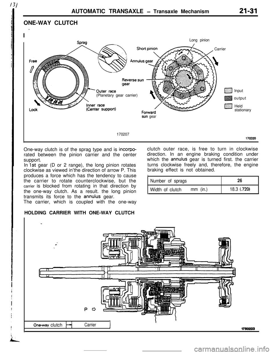
ONE-WAY CLUTCH
I
’
21-31
Long pinion(Planetary gear carrier)
CarrierInput
output
Held
stationary
sun gear
170207170320One-way clutch is of the sprag type and is
incorpo-rated between the pinion carrier and the center
support.
In
1st gear (D or 2 range), the long pinion rotates
clockwise as viewed in’the direction of arrow P. This
produces a force which has the tendency to cause
the carrier to rotate counterclockwise, but the
carrier is blocked from rotating in that direction by
the one-way clutch. As a result. the long pinion
transmits its force to the
annulus gear.
The carrier, which is coupled with the one-wayclutch outer race, is free to turn in clockwise
direction. In an engine braking condition under
which the
annulus gear is turned first. the carrier
turns clockwise freely and, therefore, the engine
braking effect is not obtained.
INumber of sprags26
Width of clutchmm (in.)18.3 (720)HOLDING CARRIER WITH ONE-WAY CLUTCH
P 0
On-y clutchI
\Carrierl7so223
Page 257 of 391
AUTOMATIC TRANSAXLE - Transaxle Mechanism21-33
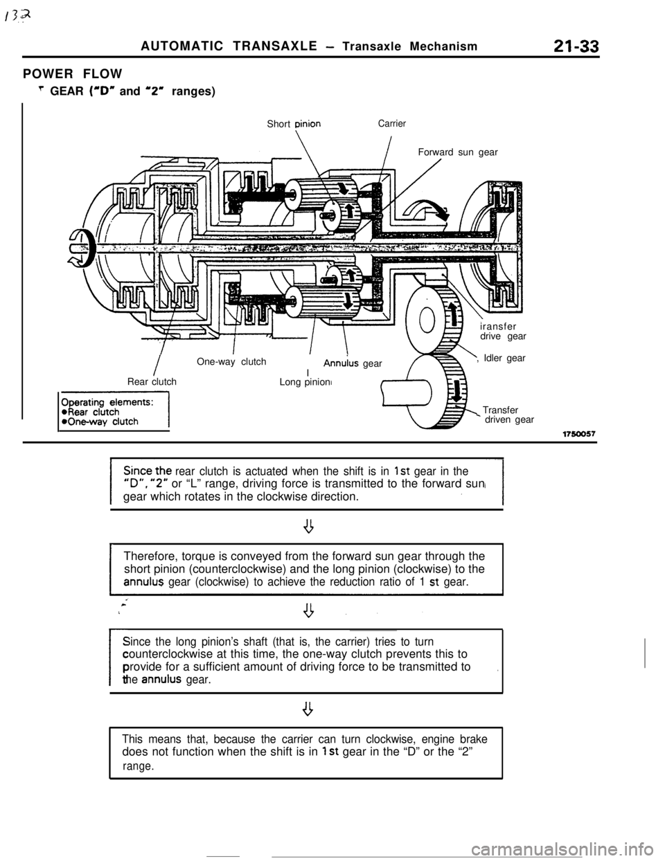
POWER FLOW
T GEAR (“D” and ‘2” ranges)
Short
DinionCarrier
IForward sun gear
IOne-way clutch
IAnn&s gear
Rear clutch
-1Long pinioniransfer
drive gear
, Idler gear
Transfer* driven gear
17!50057
rear clutch is actuated when the shift is in 1 st gear in the
“D”. “2” or “L” range, driving force is transmitted to the forward sun
gear which rotates in the clockwise direction.
ITherefore, torque is conveyed from the forward sun gear through the
short pinion (counterclockwise) and the long pinion (clockwise) to theannulus gear (clockwise) to achieve the reduction ratio of 1 st gear.
Since the long pinion’s shaft (that is, the carrier) tries to turn
/counterclockwise at this time, the one-way clutch prevents this to
provide for a sufficient amount of driving force to be transmitted to
.
the annulus gear.
,
This means that, because the carrier can turn clockwise, engine brakedoes not function when the shift is in
1 st gear in the “D” or the “2”
range.
Page 259 of 391
2ND’ GEARAUTOMATIC
TRANSAXLE - Transaxle Mechanism21-35
Kickdown brake
I
Shon pinion
\Forward sun gear
1.//LT.//. , ,’ .‘,,i.:,;:.:‘.,.‘,\/
/
Annulus gearLong pinion
Rear clutch/Reverse sun gear
fharatinn damants:
-, IWI WUIUI IWickdown brakeI
.
c
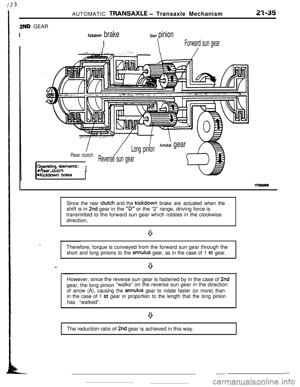
Since the rear clutch and the kickdown brake are actuated when theshift is in
2nd gear in the “0” or the “2” range, driving force is
transmitted to the forward sun gear which rotates in the clockwise
direction,
Therefore, torque is conveyed from the forward sun gear through the
short and long pinions to the annulus gear, as in the case of 1 st gear.
--However, since the reverse sun gear is fastened by in the case of
2ndgear, the long pinion“walks” on the reverse sun gear in the direction
of arrow (A), causing the annulus gear to rotate faster (or more) than
in the case of 1 st
gear in proportion to the length that the long pinionhas “walked”.
The reduction ratio of
2nd gear is achieved in this way.
---
Page 260 of 391
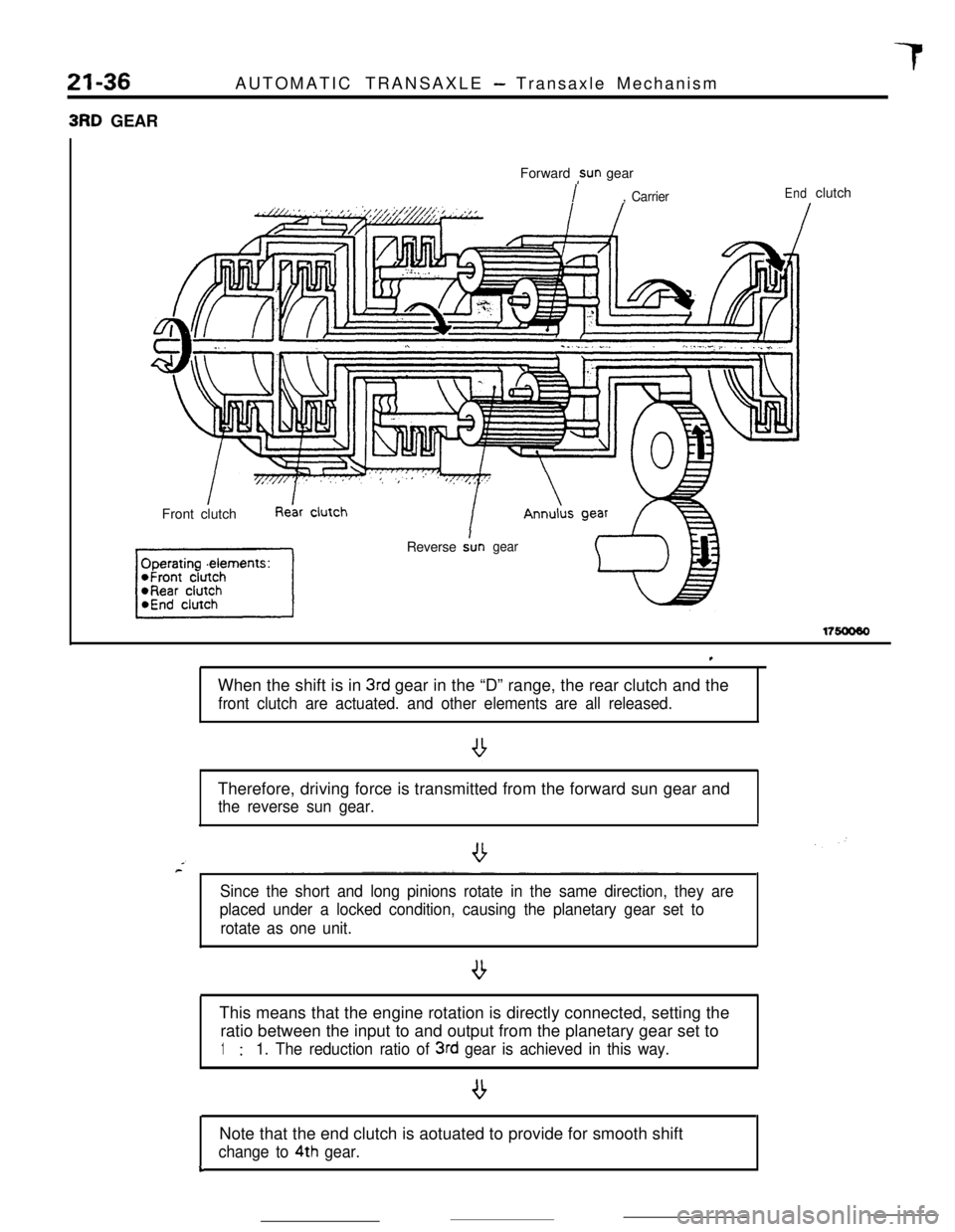
21-36AUTOMATIC TRANSAXLE - Transaxle Mechanism3RD GEAR
Forward
,sun gear
I, CarrierEndclutch
Front clutch
Reverse
Angear
17soo60
,When the shift is in
3rd gear in the “D” range, the rear clutch and the
front clutch are actuated. and other elements are all released.Therefore, driving force is transmitted from the forward sun gear and
the reverse sun gear.
Since the short and long pinions rotate in the same direction, they are
placed under a locked condition, causing the planetary gear set to
rotate as one unit.
lThis means that the engine rotation is directly connected, setting the
ratio between the input to and output from the planetary gear set to
1:1. The reduction ratio of 3rd gear is achieved in this way.Note that the end clutch is aotuated to provide for smooth shift
change to 4th gear.&
Page 262 of 391
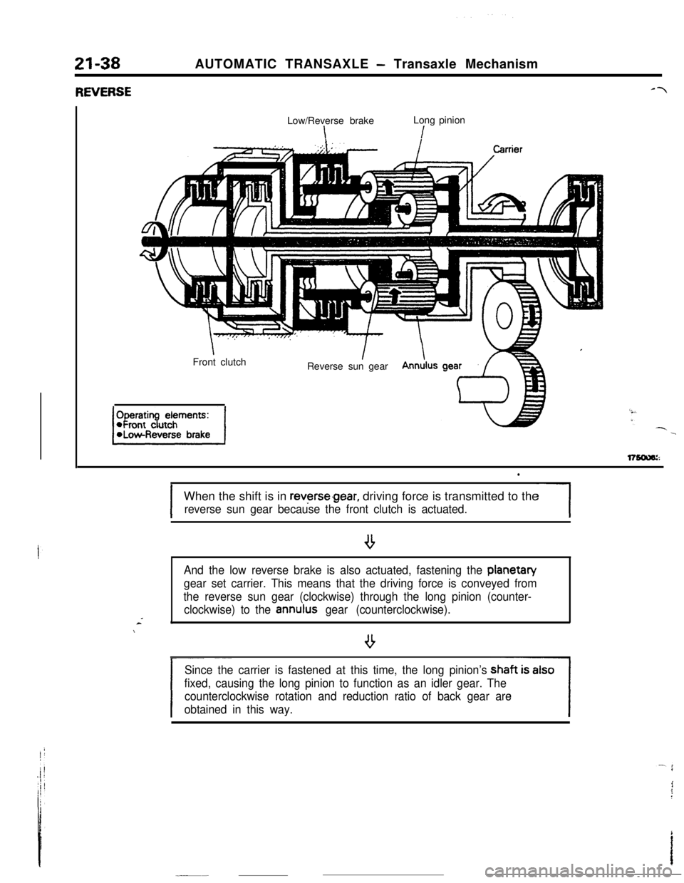
21-38RNERSEAUTOMATIC TRANSAXLE - Transaxle Mechanism
Low/Reverse brakeLong pinion
\I
IFront clutchIReverse sun gearIAnnulus
l
IWhen the shift is in
reverse.gear, driving force is transmitted to the
reverse sun gear because the front clutch is actuated.-1
And the low reverse brake is also actuated, fastening the planetan/
gear set carrier. This means that the driving force is conveyed from
the reverse sun gear (clockwise) through the long pinion (counter-
clockwise) to the
annulus gear (counterclockwise).*
/
- ~~_~
Since the carrier is fastened at this time, the long pinion’s
fixed, causing the long pinion to function as an idler gear. The
counterclockwise rotation and reduction ratio of back gear are
obtained in this way.
Page 264 of 391
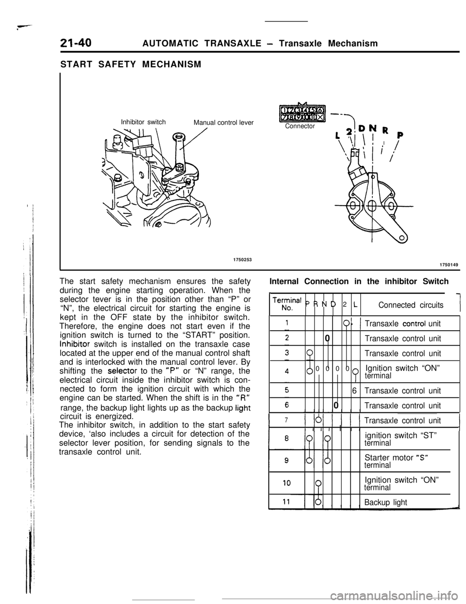
21-40AUTOMATIC TRANSAXLE - Transaxle Mechanism
START SAFETY MECHANISM
Inhibitor switch
Manual control lever
--
Connector-7DN R
‘,T,i \ ! I
‘\FlI
\ L
,p
( /1750253
1750149
Internal Connection in the inhibitor Switch
,
Teh;ina’ P R N D 2 LConnected circuits1 The start safety mechanism ensures the safety
during the engine starting operation. When the
selector tever is in the position other than “P” or
“N”, the electrical circuit for starting the engine is
kept in the OFF state by the inhibitor switch.
Therefore, the engine does not start even if the
ignition switch is turned to the “START” position.Inhibitor switch is installed on the transaxle case
located at the upper end of the manual control shaft
and is interlocked with the manual control lever. By
shifting the selector to the
“P” or “N” range, the
electrical circuit inside the inhibitor switch is con-
nected to form the ignition circuit with which the
engine can be started. When the shift is in the
“R”range, the backup light lights up as the backup
lightcircuit is energized.
The inhibitor switch, in addition to the start safety
device, ‘also includes a circuit for detection of the
selector lever position, for sending signals to the
transaxle control unit.
011Transaxle control unit0
Transaxle control unit
Transaxle control unit0000Ignition switch “ON”
terminal6
Transaxle control unit0
Transaxle control unit
I
7) 161 ) 1 ( 1Transaxle control unit
I I I I I I IIignition switch “ST”
terminalStarter motor “S”
terminal
10Ignition switch “ON”terminal
Backup light
Page 275 of 391
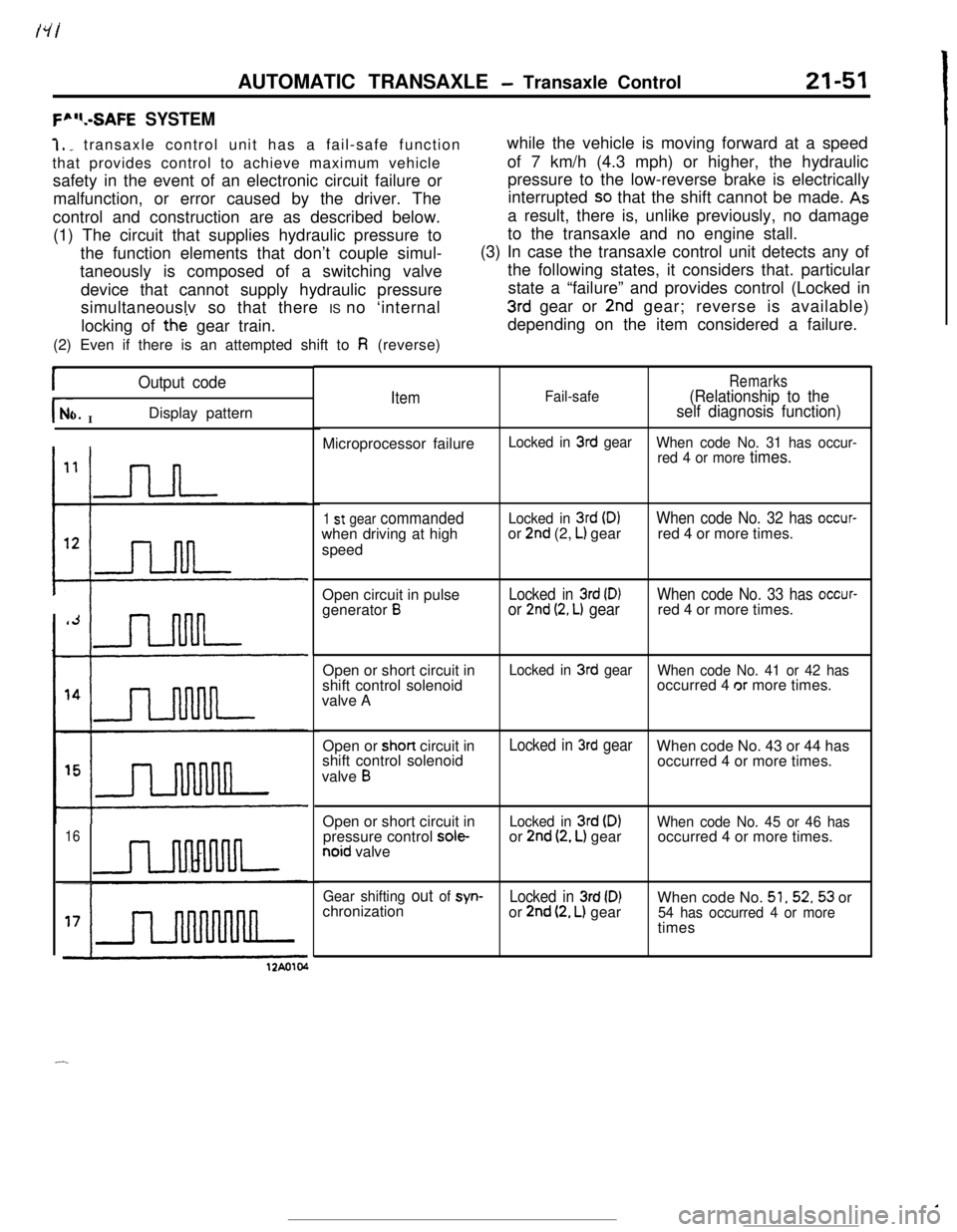
AUTOMATIC TRANSAXLE - Transaxle Control21-51
F”“.-SAFE SYSTEM7,
_ transaxle control unit has a fail-safe function
that provides control to achieve maximum vehicle
safety in the event of an electronic circuit failure or
malfunction, or error caused by the driver. The
control and construction are as described below.
(1) The circuit that supplies hydraulic pressure to
the function elements that don’t couple simul-
taneously is composed of a switching valve
device that cannot supply hydraulic pressure
simultaneouslv so that there IS no ‘internal
locking of the gear train.
(2) Even if there is an attempted shift to
Fi (reverse)while the vehicle is moving forward at a speed
of 7 km/h (4.3 mph) or higher, the hydraulic
pressure to the low-reverse brake is electrically
interrupted
SO that the shift cannot be made. Asa result, there is, unlike previously, no damage
to the transaxle and no engine stall.
(3) In case the transaxle control unit detects any of
the following states, it considers that. particular
state a “failure” and provides control (Locked in
3rd gear or 2nd gear; reverse is available)
depending on the item considered a failure.
IOutput code
r- INo.Display pattern
16
ItemFail-safeRemarks(Relationship to the
self diagnosis function)Microprocessor failure
Locked in 3rd gear
When code No. 31 has occur-
red 4 or more
times.
1 st gear commandedwhen driving at high
speedLocked in 3rd (D)or 2nd (2, L) gearWhen code No. 32 has occur-red 4 or more times.
Open circuit in pulse
generator
BLocked in 3rd (D)or 2nd (2, L) gearWhen code No. 33 has occur-red 4 or more times.
Open or short circuit in
shift control solenoid
valve A
Locked in 3rd gear
When code No. 41 or 42 hasoccurred 4 or more times.
Open or short circuit in
shift control solenoid
valve
B
Locked in 3rd gearWhen code No. 43 or 44 has
occurred 4 or more times.
Open or short circuit in
pressure control
sole-noid valve
Locked in 3rd (DIor 2nd (2, L) gearWhen code No. 45 or 46 hasoccurred 4 or more times.
Gear shifting out of syn-Locked in 3rd (D)When code No. 51,52,53 or
chronization
or 2nd (2, L) gear54 has occurred 4 or moretimes
12Ao104
-
Page 276 of 391
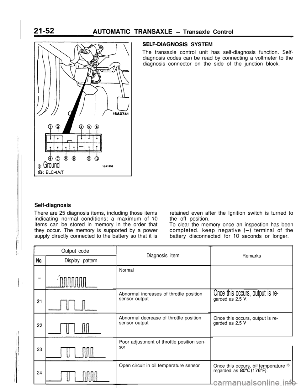
AUTOMATIC TRANSAXLE - Transaxle ControlSELF-DIAGNOStS SYSTEM
The transaxle control unit has self-diagnosis function.
Self-diagnosis codes can be read by connecting a voltmeter to the
diagnosis connector on the side of the junction block.
0: Ground
6%: ELC-MIT
Self-diagnosisThere are 25 diagnosis items, including those items
indicating normal conditions; a maximum of
10items can be stored in memory in the order that
they occur. The memory is supported by a power
supply directly connected to the battery so that it isretained even after the Ignition switch is turned to
the off position.
To clear the memory once an inspection has been
completed. keep negative
(-) terminal of the
battery disconnected for
10 seconds or longer.
r
No.
23
24
Output code
Display pattern
TDiagnosis itemRemarks
NormalAbnormal increases of throttle position
sensor output
Abnormal decrease of throttle position
sensor output
Poor adjustment of throttle position sen-
sorOpen circuit in oil temperature sensor
Once this occurs, output is re-
garded as 2.5 V.Once this occurs, output is re-
garded as 2.5 VOnce this occurs,
oil temperature isregarded as 80°C (176°F).
Page 288 of 391
/
1. .)
21-66
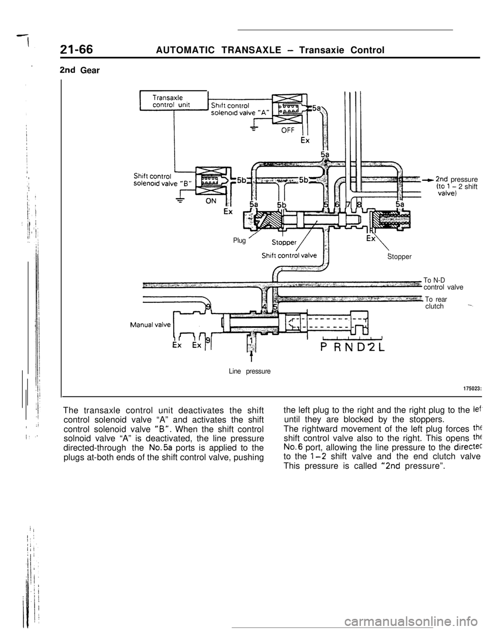
2nd GearAUTOMATIC TRANSAXLE
- Transaxie Control
Plug ’
- 2nd pressure‘:“,,tol, 2 shift
Stopper
To N-Dcontrol valve
To rearclutch -.
Line pressure
175023:The transaxle control unit deactivates the shift
control solenoid valve “A” and activates the shift
control solenoid valve
“B”. When the shift control
solnoid valve “A” is deactivated, the line pressure
directed-through the
No.5a ports is applied to the
plugs at-both ends of the shift control valve, pushingthe left plug to the right and the right plug to the
lef’until they are blocked by the stoppers.
The rightward movement of the left plug forces
theshift control valve also to the right. This opens
theNo.6 port, allowing the line pressure to the
directecto the
l-2 shift valve and the end clutch valve
This pressure is called
“2nd pressure”.