lock MITSUBISHI ECLIPSE 1990 Owner's Guide
[x] Cancel search | Manufacturer: MITSUBISHI, Model Year: 1990, Model line: ECLIPSE, Model: MITSUBISHI ECLIPSE 1990Pages: 391, PDF Size: 15.27 MB
Page 181 of 391
FUEL SYSTEM- Auto-cruise Control System14-69
ni2nnncisv,“y’I”“.-
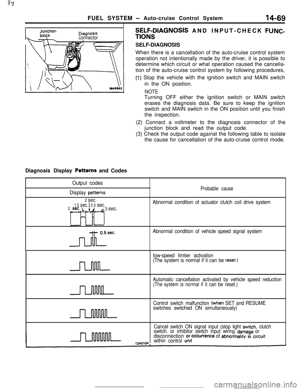
connectorDiagnosis Display Patterns and Codes
SELF-D’IAGNOSIS AND INPUT-CHECK FUNC-
TIONSSELF-DIAGNOSIS
When there is a cancellation of the auto-cruise control system
operation not intentionally made by the driver, it is possible to
determine which circuit or what operation caused the cancella-
tion of the auto-cruise control system by following procedures,
(1) Stop the vehicle with the ignition switch and MAIN switch
in the ON position.
NOTETurning OFF either the ignition switch or MAIN switch
erases the diagnosis data. Be sure to keep the ignition
switch and MAIN switch in the ON position until you finish
the inspection.
(2) Connect a voltmeter to the diagnosis connector of the
junction block and read the output code.
(3) Check the output code against the following table to isolate
the cause for cancellation of the auto-cruise control mode.
Output codes
Display
patterns
2 sec.
1.5 sec.I0.5 sec.3sec. id 3 sec.
L3o-l
-Jdrec.
Probable cause
Abnormal condition of actuator clutch coil drive system
Abnormal condition of vehicle speed signal system
tow-speed limiter activation
(The system is normal if it can be
reset.1
n
Automatic cancellation activated by vehicle speed reduction
(The system is normal if it can be reset.)
Control switch malfunction (when SET and RESUME
switches switched ON simultaneously)
Cancel switch ON signal input (stop light
switch, clutch
switch. or inhibitor switch input wiring damage ordisconnection or,occurrence of abnormality in circuitwithin control unit
Page 182 of 391
14-70
-_FUEL SYSTEM
- Auto-cruise Control System
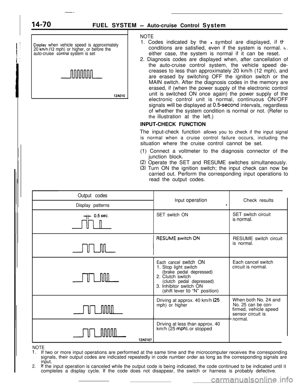
Display when vehicle speed is approximately
20 km/h (12 mph) or higher, or before the
auto-cruise conrrol system is set
12AolO
NOTE1. Codes indicated by thel symbol are displayed, if
tt-conditions are satisfied, even if the system is normal.
I,.either case, the system is normal if it can be reset.
2. Diagnosis codes are displayed when, after cancellation of
the auto-cruise control system, the vehicle speed de-
creases to less than approximately 20 km/h (12 mph), and
are erased by switching OFF the ignition switch or the
MAIN switch. After the diagnosis codes in the memory are
erased, if (when the power supply of the electronic control
unit is switched ON once again) the power supply of the
electronic control unit is normal, continuous ON/OFF
signals will be displayed at
O.&second intervals, regardless
of whether the system condition is normal or not. (Refer to
the illustration at the left.)
INPUT-CHECK FUNCTION
The input-check function allows you to check if the input signal
is normal when a cruise control failure occurs, including the
situation where the cruise control cannot be set.
(1) Connect a voltmeter to the diagnosis connector of the
junction block.
(2) Operate the SET and RESUME switches simultaneously.
(3) Turn ON the ignition switch; the input check can now be
carried out. Perform the corresponding input operations to
read the output codes.
Output codes
Display patternsInput
operationCheck resultst
y- 0.5sec.
n
SET switch ONSET switch circuitis normal.RESUME switch circuit
is normal.
Each cancel switch ON1. Stop light switch
(brake pedal depressed)2. Clutch switch
(clutch pedal depressed)3. Inhibitor switch ON
(shift lever to “N” position)Each cancel switch
circuit is normal.
Driving at approx. 40 km/h
(25mph) or higherWhen both No. 24 andNo. 25 can be con-firmed, vehicle speed
sensor circuit is
normal.Driving at less than approx. 40
km/h (25
mph). or stopped
NOTE1.If two or more input operations are performed at the same time and the microcomputer receives the corresponding
signals, their output codes are indicated repeatedly in code number order as long as the corresponding signals are
2.input.If the input operation is canceled while the output code is being indicated, the code continued to be indicated until it
completes a display cycle. If the code does not disappear, the switch or harness is probably defective.
Page 213 of 391
19-4POWER STEERING - Tilt Steering Construction
TILT STEERING CONSTRUCTIONRlW
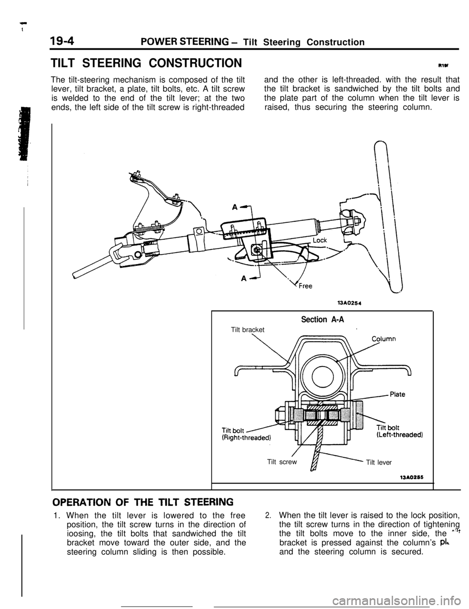
The tilt-steering mechanism is composed of the tilt
lever, tilt bracket, a plate, tilt bolts, etc. A tilt screw
is welded to the end of the tilt lever; at the two
ends, the left side of the tilt screw is right-threadedand the other is left-threaded. with the result that
the tilt bracket is sandwiched by the tilt bolts and
the plate part of the column when the tilt lever is
raised, thus securing the steering column.
13A0254Tilt bracket
Section A-A.
’Tilt screwfi Tilt lever13AO256
OPERATION OF THE TILT STEERING1. When the tilt lever is lowered to the free
position, the tilt screw turns in the direction of
ioosing, the tilt bolts that sandwiched the tilt
bracket move toward the outer side, and the
steering column sliding is then possible.
2.When the tilt lever is raised to the lock position,
the tilt screw turns in the direction of tightening
the tilt bolts move to the inner side, the
*“?bracket is pressed against the column’s
pi&and the steering column is secured.
Page 234 of 391
21-10MANUAL TRANSAXLE <4WD> - General Information4WD SYSTEM OPERATION
Conventional 4WD systems (direct-coupled
4WD,or center differential type 4WDl have their own
merits and demerits; they rely on manual operation
(switching between 4WD and 2WD modes, center
differential locking) to cope with their demerits.
With this new 4WD system, the viscous coupling
built in the center differential automatically performssuch operations used to be made manually. The
driver can participate with the merits of 4WD at alltimes.The operation of the differential and the
viscous
coupling under representative conditions
are described in the following section.
I
Reardifferential
Center
differential
U differential
Viscous AuDk?TFNOO5’difference
ce271010i
TFMMYTFMMY
0
Turningdirection
ITFMOO!X
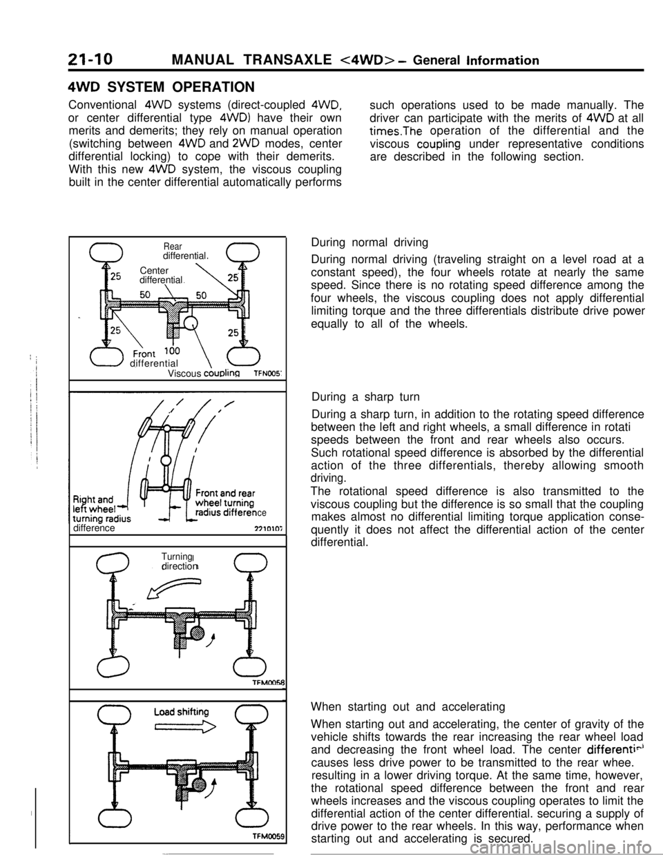
-.During normal driving
During normal driving (traveling straight on a level road at a
constant speed), the four wheels rotate at nearly the same
speed. Since there is no rotating speed difference among the
four wheels, the viscous coupling does not apply differential
limiting torque and the three differentials distribute drive power
equally to all of the wheels.
During a sharp turn
During a sharp turn, in addition to the rotating speed difference
between the left and right wheels, a small difference in rotati
speeds between the front and rear wheels also occurs.
Such rotational speed difference is absorbed by the differential
action of the three differentials, thereby allowing smooth
driving.The rotational speed difference is also transmitted to the
viscous coupling but the difference is so small that the coupling
makes almost no differential limiting torque application conse-
quently it does not affect the differential action of the center
differential.
When starting out and accelerating
When starting out and accelerating, the center of gravity of the
vehicle shifts towards the rear increasing the rear wheel load
and decreasing the front wheel load. The center
differenti”causes less drive power to be transmitted to the rear whee.
resulting in a lower driving torque. At the same time, however,
the rotational speed difference between the front and rear
wheels increases and the viscous coupling operates to limit the
differential action of the center differential. securing a supply of
drive power to the rear wheels. In this way, performance when
starting out and accelerating is secured.
Page 242 of 391
21-18AUTOMATIC TRANSAXLE - Transaxle Control
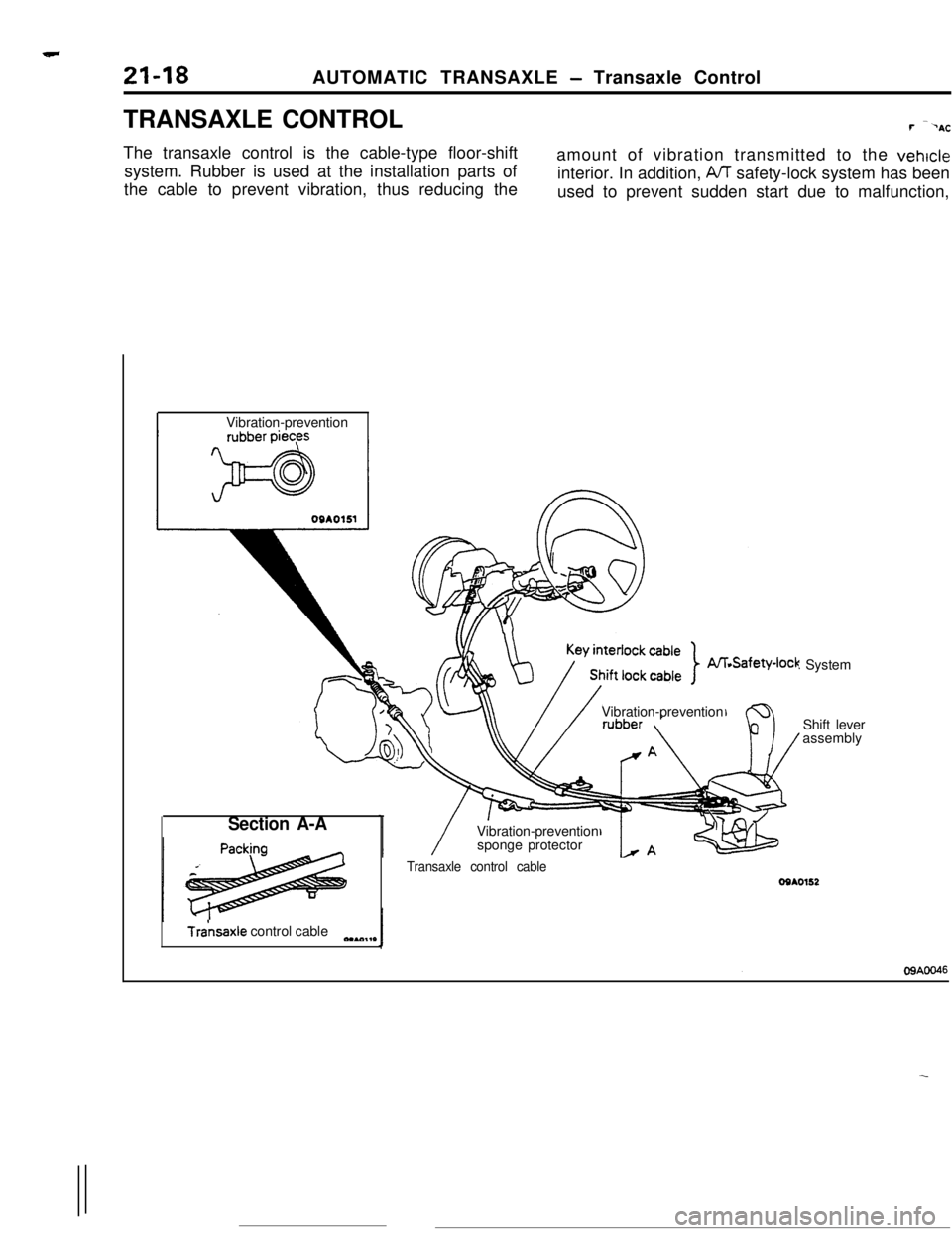
TRANSAXLE CONTROLr---AC
The transaxle control is the cable-type floor-shift
system. Rubber is used at the installation parts of
the cable to prevent vibration, thus reducing theamount of vibration transmitted to the
vehicleinterior. In addition,
A/T safety-lock system has been
used to prevent sudden start due to malfunction,
Vibration-prevention
Vibration-prevention
Vibration-prevention
sponge protector
Section A-A
Tra’nsaxle control cableeaAc.,,*
: System
Shift lever
assembly
Transaxle control cableOSAO152
Page 243 of 391
AUTOMATIC TRANSAXLE - A/T Safety-lock System21-19
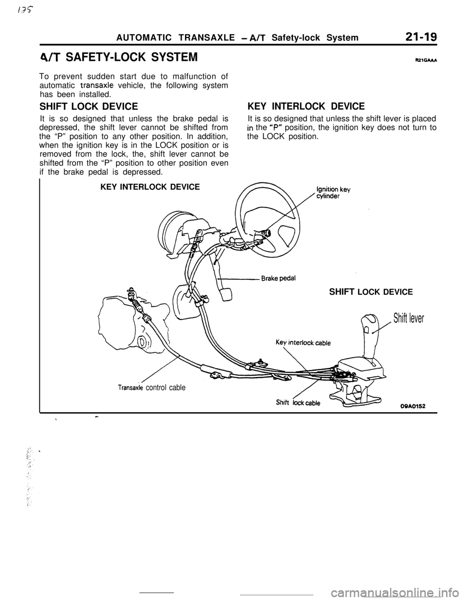
4/T SAFETY-LOCK SYSTEMRzsAAaTo prevent sudden start due to malfunction of
automatic transaxle vehicle, the following system
has been installed.
SHIFT LOCK DEVICE
It is so designed that unless the brake pedal is
depressed, the shift lever cannot be shifted from
the “P” position to any other position. In addition,
when the ignition key is in the LOCK position or is
removed from the lock, the, shift lever cannot be
shifted from the “P” position to other position even
if the brake pedal is depressed.
KEY INTERLOCK DEVICEIt is so designed that unless the shift lever is placed
in the “P” position, the ignition key does not turn to
the LOCK position.
KEY INTERLOCK DEVICE
SHIFT LOCK DEVICE
Shift lever
Transaxie control cable
Shift dieOQA0152
c\
Page 244 of 391
-_ - .--.7
!21-20AUTOMATIC TRANSAXLE - A/T Safety-lock System
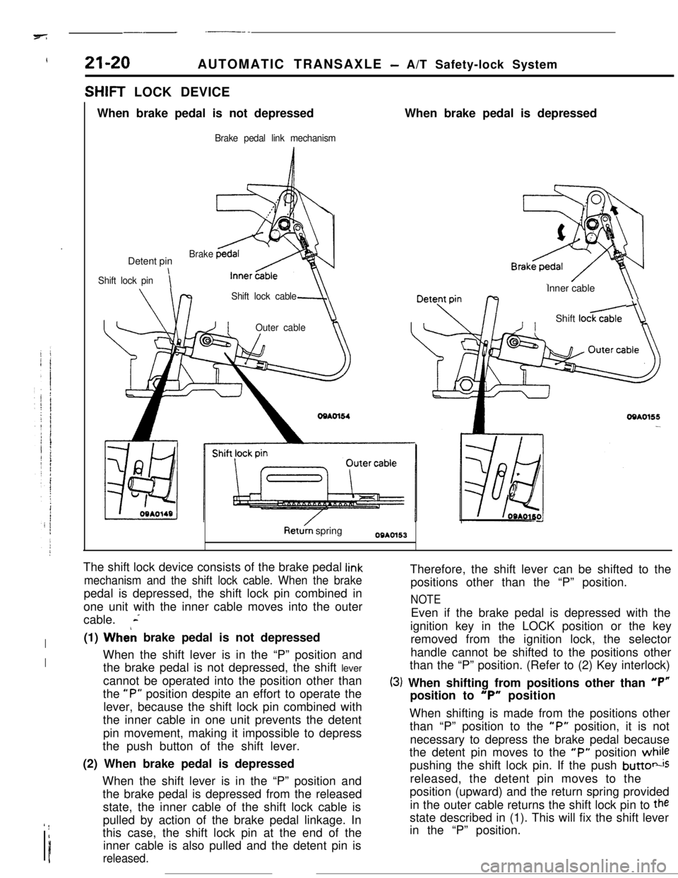
SHIFT LOCK DEVICE
When brake pedal is not depressed
Brake pedal link mechanismWhen brake pedal is depressed
Detent pin
Shift lock pini
Brake
Shift lock cable
-JIOuter cableInner cable
\\
/IShift loc&
OQAO155-
Ret& springOBAOl53
The shift lock device consists of the brake pedal
link
mechanism and the shift lock cable. When the brakepedal is depressed, the shift lock pin combined in
one unit with the inner cable moves into the outer
cable.
L
I(1) Wheh brake pedal is not depressed
IWhen the shift lever is in the “P” position and
the brake pedal is not depressed, the shift lever
cannot be operated into the position other than
the
“P” position despite an effort to operate the
lever, because the shift lock pin combined with
the inner cable in one unit prevents the detent
pin movement, making it impossible to depress
the push button of the shift lever.
(2) When brake pedal is depressed
When the shift lever is in the “P” position and
the brake pedal is depressed from the released
state, the inner cable of the shift lock cable is
’ !I
Ipulled by action of the brake pedal linkage. In
this case, the shift lock pin at the end of the
inner cable is also pulled and the detent pin isreleased.Therefore, the shift lever can be shifted to the
positions other than the “P” position.
NOTEEven if the brake pedal is depressed with the
ignition key in the LOCK position or the key
removed from the ignition lock, the selector
handle cannot be shifted to the positions other
than the “P” position. (Refer to (2) Key interlock)
(3) When shifting from positions other than “P”position to
“P” position
When shifting is made from the positions other
than “P” position to the
“P” position, it is not
necessary to depress the brake pedal because
the detent pin moves to the
“P” position whilepushing the shift lock pin. If the push
buttotisreleased, the detent pin moves to the
position (upward) and the return spring provided
in the outer cable returns the shift lock pin to
thestate described in (1). This will fix the shift lever
in the “P” position.
Page 245 of 391
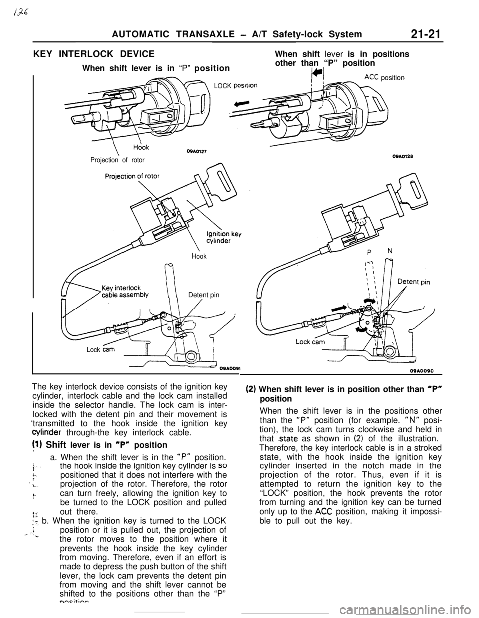
AUTOMATIC TRANSAXLE - A/T Safety-lock System21-21KEY INTERLOCK DEVICEWhen shift lever is in positions
When shift lever is in “P” position
LOCK
\Hcjok
Projection of rotorother than “P” position
KC position
Hook
\ \Detent pin
Lock &mThe key interlock device consists of the ignition key
cylinder, interlock cable and the lock cam installed
inside the selector handle. The lock cam is inter-
locked with the detent pin and their movement is
‘transmitted to the hook inside the ignition key
Q4inder through-the key interlock cable.
!l) Shift lever is in “P” position
a. When the shift lever is in the
“P” position.
j..the hook inside the ignition key cylinder is SO
i-.3positioned that it does not interfere with the’ .L.,projection of the rotor. Therefore, the rotor
:‘-can turn freely, allowing the ignition key to
be turned to the LOCK position and pulled
out there.
is, b. When the ignition key is turned to the LOCK
i,- c.position or it is pulled out, the projection of‘..the rotor moves to the position where it
prevents the hook inside the key cylinder
from moving. Therefore, even if an effort is
made to depress the push button of the shift
lever, the lock cam prevents the detent pin
from moving and the shift lever cannot be
shifted to the positions other than the “P”nnrit;nn
09*0090
(2) When shift lever is in position other than “P”position
When the shift lever is in the positions other
than the
“P” position (for example. “N” posi-
tion), the lock cam turns clockwise and held in
that
.state as shown in (2) of the illustration.
Therefore, the key interlock cable is in a stroked
state, with the hook inside the ignition key
cylinder inserted in the notch made in the
projection of the rotor. Thus, even if it is
attempted to return the ignition key to the
“LOCK” position, the hook prevents the rotor
from turning and the ignition key can be turned
only up to the
ACC position, making it impossi-
ble to pull out the key.
Page 246 of 391
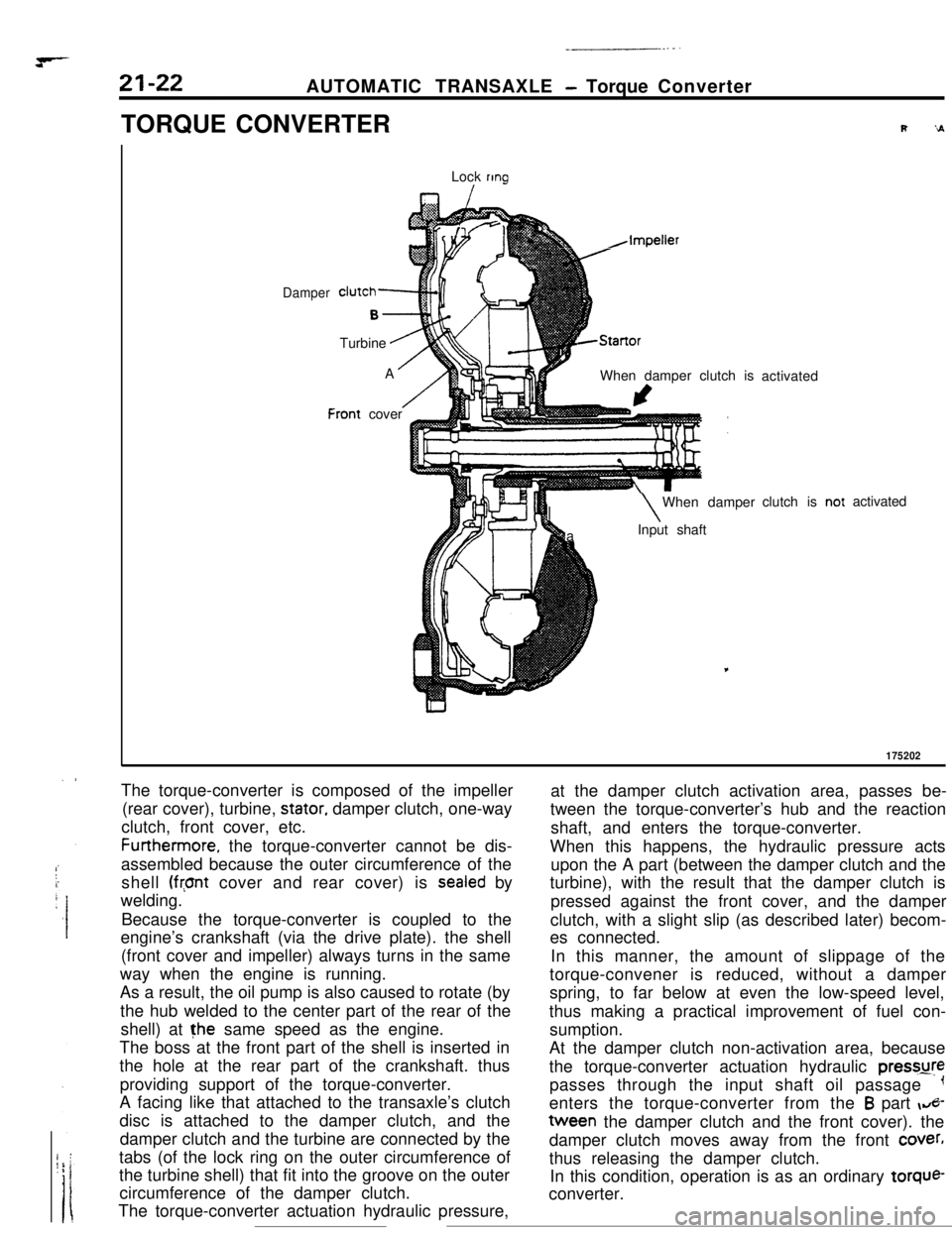
AUTOMATIC TRANSAXLE - Torque Converter
TORQUE CONVERTER
Lock
ring
I
Damper
F
clutch-
B-.Turbine
.AA
/:ront cover
h,Impeller
AStartorWhen damper clutch is
I\When damper
aInput shaftactivated
clutch isactivated
175202The torque-converter is composed of the impeller
(rear cover), turbine,
stator, damper clutch, one-way
clutch, front cover, etc.Furthermore. the torque-converter cannot be dis-
assembled because the outer circumference of the
shell
(front cover and rear cover) is sealed by
welding.
Because the torque-converter is coupled to the
engine’s crankshaft (via the drive plate). the shell
(front cover and impeller) always turns in the same
way when the engine is running.
As a result, the oil pump is also caused to rotate (by
the hub welded to the center part of the rear of the
shell) at the same speed as the engine.
The boss at the front part of the shell is inserted in
the hole at the rear part of the crankshaft. thus
providing support of the torque-converter.
A facing like that attached to the transaxle’s clutch
disc is attached to the damper clutch, and the
damper clutch and the turbine are connected by the
tabs (of the lock ring on the outer circumference of
the turbine shell) that fit into the groove on the outer
circumference of the damper clutch.
The torque-converter actuation hydraulic pressure,at the damper clutch activation area, passes be-
tween the torque-converter’s hub and the reaction
shaft, and enters the torque-converter.
When this happens, the hydraulic pressure acts
upon the A part (between the damper clutch and the
turbine), with the result that the damper clutch is
pressed against the front cover, and the damper
clutch, with a slight slip (as described later) becom-
es connected.
In this manner, the amount of slippage of the
torque-convener is reduced, without a damper
spring, to far below at even the low-speed level,
thus making a practical improvement of fuel con-
sumption.
At the damper clutch non-activation area, because
the torque-converter actuation hydraulic pressure
passes through the input shaft oil passage
-1enters the torque-converter from the
B part &-tween the damper clutch and the front cover). the
damper clutch moves away from the front
cover,thus releasing the damper clutch.
In this condition, operation is as an ordinary torque-
converter.
Page 248 of 391
21-24AUTOMATIC TRANSAXLE - Transaxle Mechanism
SELECT PATTERN
Select pattern refers to the indication of transaxle
positions to be manually selected by the driver. This
transaxie is provided with 6 positions: P-R-N-D-
2-L. The following contains the explanations of the
function of each position selected.
P-Parking
(1)
(2)
(3)
Each element does not operate at all. Therefore,the engine output is not transmitted to the
output shaft.
The output shaft is completely locked by mecha-
nical means. Therefore, the vehicle does not
move in forward or reverse direction.
The engine can be started.
R-Reverse
(1) The vehicle moves in reverse direction.
(2) The engine cannot be started.
N-Neutral
(1) The engine output is not transmitted to the
output shaft as in the case of
“P”(2) The engine can be started.
D-Drive
(1)
(2)
(3)Corresponding with the degree that the
accelerator pedal is pressed down (i.e. throttle
opening) and vehicle speed,
“D” automatically
shifts between forward 4 speeds. Note, howev-
er,’ that the forward 3 speeds are selected when
the overdrive control switch is OFF. The automa-tic shifting (up or down) is performed according
to the shift pattern shown in the illustration on
page 2
l-30.Driving-off is always performed in
1st gear.Kickdown refers to the downshift that is per-
formed if the accelerator pedal is pressed down
(4)
(5)when the vehicle is running. in
2nd. 3rd or 4t,.
gear. It is performed when the load exceeds the
downshift point.
This function
IS useful when the driver isaccelerating to pass another vehicle.
Engine brake does not function when the shift is
in
1st gear.
When the vehicle is stopped, shifting is made to
the
2nd gear to minimize creep and vibration.
Upon starting, shifting is made to
1st gear.
S-Second
(1)
(2)
(3)“2” automatically shifts between
1st and 2ndgears. This means no upshift to
3rd gear occurs.
Driving-off is always performed in
1st gear.
Downshift to
2nd or 3rd gear is performed by
selecting the“2” range while the vehicle is
running in
3,rd or 4th gear, when a speed lower
than the set value is reached.
(4)As in the case of the “D” range, engine brake
does not work when the shift is in
1st gear.
L-Lock-up
(1)
(2)
(3)While “L” (Lock-up) performs downshift from
2nd to 1st gear, it does not shift up the gear
from
1st to 2nd or 3rd. The enables what is_.called
“1st gear holding”.
Driving-off is always performed in
1st gear.
Engine brake functions in the case of this
1st
gear..By selecting the “L” range while the vehicle is
running in the
“0” or “2” range, downshift from4th to
3rd, 3rd to 2nd, or 2nd to 1st is performed
when the vehicle reaches the respective speed
prescribed for each gear.